Table of Contents
Advertisement
Quick Links
Advertisement
Table of Contents

Related Manuals for Nanni N2.10


Summary of Contents for Nanni N2.10
- Page 1 Nanni marine engine Operator’s manual Engines N2.10 N2.14 N3.21...
-
Page 2: Table Of Contents
ONTENTS Introduction ......1 Maintenance ......32 About this manual ......2 Service schedule ......33 General inspection ......35 Safety ........3 Fuel system ........37 Emergency kit ......3 Lubrication system .....41 Safety alert symbols .....3 Cooling system ......43 Safety icons ........4 Raw water system ......47 Safety precautions .......5 Electrical system ......53 About the engine ......9... -
Page 3: Introduction
NTRODUCTION Thank you for choosing a Nanni product! Contact a Nanni authorized dealer for the servicing of your product. A list of dealers can be found on our web site: www.nannidiesel.com Nanni engines are the product of many years of experience in the deve- lopment of marine engines and equipment designed for use in open seas. -
Page 4: About This Manual
We urge you time of its publication. Changes and to read it carefully and familiarize updates may be made by Nanni yourself with the engine before without notice. starting. Illustrations are intended as a... -
Page 5: Safety
I CAUTION Indicates a hazardous situation You can order an emergency kit which, if not avoided, could re- from any Nanni authorized dealer. sult in minor or moderate injury, or could cause property damage. The engine emergency kit contains several components to carry out simple repair in the event of a fault. -
Page 6: Safety Icons
Safety icons Indicates where to check the coolant level. Several stickers are fixed directly on the engine. They are intended Indicates where to check the to help you to quickly identify the engine oil level. location of certain components and avoid possible hazards when working on the engine. -
Page 7: Safety Precautions
Safety Burns precautions Never touch the hot parts of the engine! An operational engine gets very hot: the exhaust system, tur- Exhaust gas bocompressor (if equipped), starter, oil sump, oil, coolant in the hoses Exhaust gases contain carbon and pipes are hot and can burn. monoxide. - Page 8 Hazardous Voltage/ Immediately clean up any liquids Electrical Shock spilled and keep the engine com- partment clean and accessible so as to minimise the risk of fire. Be Electrocution is possible whenever careful as fuel can burn. Damaged electricity is present. Hazardous pipes can lead to fire.
-
Page 9: Rotating Parts
Special attention must be brought Ventilate correctly storage batteries on boat with metallic hull, especially compartment. Avoid touching the concerning the protection of the battery terminals with metal tools persons against electrical shock so that no sparks are created which and the protection against galvanic could cause an explosion. - Page 10 Chemical products do not start the engine, except in extreme emergencies, and contact The different fluids used to run the an authorized Nanni dealer. engine are a health hazard. Ca- refully read the instructions on the packaging of these products and always check that the ventilation in the hold space is adequate.
-
Page 11: About The Engine
The engine identification plate is as follow: Engine installation The installation must be carried out by an authorized Nanni workshop in accordance with the installation instructions. Correct installation of the engine is of the greatest importance for safe navigation and protection of the environment. - Page 12 The boat speed is Consult the boat builder or your reduced by 30% to 70%. Nanni dealer if you are not sure about the operation of the remote I CAUTION control. The Trolling valve system must never be used for manoeuvring.
- Page 13 Operation in cold Oil viscosity weather conditions Use seasonal grade viscosity engine oil based on the expected Nanni engines are designed to ope- air temperature range between oil rate effectively in cold weather. changes. However, for effective starting Follow the diagram below to adapt...
-
Page 14: Environmental Responsibility
Engine homologation Environmental responsibility The engine type can be exhaust emission certified. It means that Nanni designs its engines to have Nanni guarantees that all engines minimum environmental impact. of the same type that are manufac- This objective, however, can only... - Page 15 By registering the product, you will void the Warranty. receive the best warranty coverage possible and Nanni will be able to The validity of the Warranty is also contact you in the event of updates dependent on proper installation or service notifications.
-
Page 16: About The Propeller
A bout the Behaviour of the propeller boat The propeller is a critical compo- If this is your first boat or if you are nent of the propulsion system. It not familiar with the boat, we urge converts the engine power in thrust. you to practice controlling the boat To be efficient, the propeller must at slow speed as a first step. -
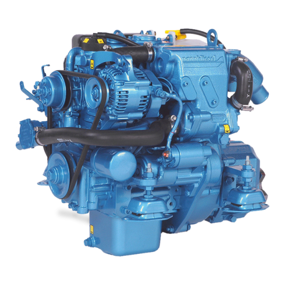
Page 17: Engine Main Components
Engine main components NOTICE: The engine may not be exactly as represented here. Some com- ponents may not be part of the engine ordered. COMPONENTS 1 Alternator 2 Alternator belt 3 Starter 4 Fuses box 5 Air filter 6 Fuel filter 7 Fuel feed pump 8 Fuel injection pump 9 Heat exchanger... - Page 18 N2.10...
- Page 19 N2.14...
- Page 20 N3.21...
-
Page 21: Instruments Panel
NOTICE: This chapter only des- NOTICE: The Eco4 panel is only cribes instruments and panels that available with the engine model come standard on Nanni engines. N2.10. Contact your dealer if the boat is fit- ted with instruments not described... -
Page 22: Instrumentation
The function of the warning lamps is explained in the following pages. NOTICE: As standard, the en- gine model N2.10 is not fit with an electric stop function. A mechanical stop control has to be installed to stop the engine. -
Page 23: Engine Oil Pressure
Engine oil pressure Coolant temperature indicator indicator NOTICE: This indicator does not Indicates the coolant temperature in show the engine oil level. This Celsius and in Fahrenheit degrees. indicator shows the oil pressure in If the coolant temperature is too bar and psi. - Page 24 Do not operate the engine if the sea cock is open. the problem persist and contact a Nanni workshop as soon as Operating the engine while possible. the coolant temperature is too high can lead to severe engine damage.
- Page 25 tion. Operate the engine when the oil pressure is too low can lead to severe engine damage. Do not operate the engine if the pro- blem persist and contact a Nanni workshop as soon as possible.
- Page 26 Note...
-
Page 27: Operation
PERATION Before starting 2. Start the compartment fan (if fitted) for at least five minutes. Otherwise, open the hold. I WARNING 3. Check that there is sufficient Put all the protective covers back fuel. before starting the engine. 4. Move the control lever to the neutral position. -
Page 28: Starting The Engine
Starting the Starting using booster batteries engine I CAUTION I DANGER Make sure to use batteries with The propeller can cause se- the same rated voltage as the rious injury when rotating. Check engine’s system voltage. that nobody is in the water near the propeller before starting. - Page 29 Panel with key Panel without key 1. Move the control lever to the 1. Switch the key of the main pa- neutral position. nel to ignition (if equipped). 2. Push the manual stop control (if 2. Move the control lever to the fitted).
-
Page 30: During Operation
During operation Manoeuvring I WARNING I CAUTION Shifting at high speed can da- Never press the START button mage both the engine and the when the engine is running. transmission and be dangerous for passengers. Check the instruments and warning lamps after starting, and regularly when cruising. - Page 31 Sailing with the engine I CAUTION stopped Sailing with the engine stop- ped and the lever in neutral must not exceed 6 to 7 hours in a row. The propeller can drive the rota- tion of the shaft and damage the transmission.
-
Page 32: Stopping The Engine
Stopping the I CAUTION engine Even after the engine has stopped, some components and I CAUTION fluids remain hot and pressuri- sed for several minutes. As far Never stop the engine by using as possible, limit work on the en- the main switch. - Page 33 It is ALL THESE OPERATIONS necessary to drain regularly the wa- SHOULD BE CARRIED OUT BY terlock when the boat is at anchor. A NANNI AUTHORIZED WORKS- HOP. ...
-
Page 34: Maintenance
AINTENANCE We recommend to have all your I WARNING works checked by a Nanni autho- rized workshop. As far as possible, perform maintenance operations with the Independent repair and adjust- engine stopped, remove the key ment work on the engine beyond a... -
Page 35: Service Schedule
100 hours or every year, and so on. Some components may not be part of the engine ordered. Operations marked with should be done in a Nanni workshop. * Operations to perform after 20 operating hours or 45 days after commis- sioning. - Page 36 EVERY 200 OPERATING HOURS / AT LEAST EVERY YEAR. Change the engine and transmission oil *. Change the oil filters *. Change the fuel filters *. Check the raw water pump impeller. Change if needed. Check the engine flexible mountings. Adjust as necessary *. ...
-
Page 37: General Inspection
(rust, crack, etc), the control cable If too much water comes in, stop must be changed. the engine and contact your Nanni dealer as soon as possible. In any case, always make sure that the lubrication of the stuffing box is... -
Page 38: Exhaust System
Exhaust system The reliability and the performances of the engine depend among other Inspect all exhaust system com- things on the quantity and the tem- ponents (hoses, clamps, mixing perature of the intake air. elbow, manifold, etc.) Check for To check the air filter: cracks, leaks and corrosion. -
Page 39: Fuel System
NOTICE: All work on the fuel injec- engine fuel filter. It must never be tion system must be carried out by a installed on the engine as vibra- authorized Nanni technician. tions affect the water/fuel separa- tion process. Check regularly the condition of... -
Page 40: Fuel Requirements
Fuel requirements Fuel prefilter Only use grade of fuels indicated The fuel prefilter is an optional ex- in the chapter TECHNICAL DATA. tra not in the scope of supply of the Other grades of fuel can increase engine. The model of prefilter can fuel consumption and cause opera- vary according the boat. -
Page 41: Replacing The Fuel Filter
Replacing the fuel filter ENGINE MODEL N2.14 & N3.21 NOTICE: Do not fill the new filter with fuel before assembly. ENGINE MODEL N2.10: N2.14 - N3.21 1. Close the fuel cock. Clean the filter bracket. N2.10 2. Put a plastic bag over the filter 1. - Page 42 Air bleeding To bleed the fuel system IF IT IS FITTED WITH AN ADDITIONAL Bleeding the air in the fuel system ELECTRIC FUEL FEED PUMP : is necessary : 1. Fill totally the fuel tank. Open the fuel cock. • After a maintenance operation on the fuel system.
-
Page 43: Lubrication System
Lubrication The oil level should be within the range indicated on the dipstick, system between the Mini and Max level. To check the oil level: I DANGER 1. Remove and wipe the dipstick. Carry out these operations with 2. Re-insert and remove the the engine stopped and cold. -
Page 44: Draining The Engine Oil
3. Connect a disposal hose to the drain pump and place a container under the disposal hose. NOTICE: On the engine model N2.10, the oil pump has to be 1. Remove the oil filter with a filter connected to the dipstick port. wrench. Remove the gasket. -
Page 45: Cooling System
• The RAW WATER CIRCUIT Exhaust elbow which cools the coolant via heat Heat exchanger exchange with raw water. Nanni engines comes as standard with Recovery tank (if fi tted) an heat exchanger, in which the coolant is cooled by heat... - Page 46 Nanni an extended period. Poor quality Industries S.A.S. France. antifreeze has poor content of corrosion preventive. The content further becomes less potent with the dilution of water.
-
Page 47: Coolant Level
Coolant level NOTICE: The Min and Max level indicated on the recovery tank (if fitted) does not indicate the correct I DANGER level of coolant. Never open the coolant filler cap Draining the coolant or any plug of the cooling system when the engine is operating circuit or warm. - Page 48 Coolant - Filling 5. Replace the coolant filler plug and add coolant in the recovery Mix the anti-freeze with water in a tank if necessary. clean container before filling the 6. Start the engine and let it ope- heat exchanger. The coolant must rate few minutes at idle.
-
Page 49: Raw Water System
Raw water system Siphon breaker I DANGER I DANGER Close the sea cock before any When the boat is in the water, operation on the siphon breaker. water can flow into the boat via components located below the waterline. Close the raw water NOTICE: The use of a siphon cock (if fitted) or prevent water breaker is mandatory if the exhaust... - Page 50 Raw water pump impel- 4. Mark the position of the neo- prene impeller inside the pump in order to install it in the correct position in case of reins- I CAUTION tallation. If the engine has been run wi- 5. Carefully remove the impeller thout supply of raw water, check using an extractor.
- Page 51 Cleaning the raw water R aw water system - filter Draining A raw water filter must be fitted I WARNING between the raw water intake and the raw water pump of the engine. It is highly recommended to carry out these operations when The model of prefilter can vary the boat is laid up on land.
- Page 52 Raw water system - 6. Stop the engine. Cleaning and inhibiting 7. Fill the container with engine coolant mix (50% clean water, The raw water system must be 50% anti-freeze). flushed with fresh water to prevent the buildup of deposits and salt 8.
-
Page 53: Electrical System
Change it if any defect appears. Contact your Nanni dealer for more informations. Tighten the cable terminals and lubricate them with appropriate grease. -
Page 54: Battery
Contact discharging, notably in wet weather. an authorized Nanni dealer. Use a brass brush to clean battery terminals. BATTERY STORAGE When DISCONNECTING the... -
Page 55: Alternator Belt
Alternator belt To adjust the belt tension: I DANGER Stop the engine and remove the key before servicing the alterna- tor belt. Always keep a replacement belt on-board. The alternator belt drives both the coolant pump and the alternator. Additional belt can also be fitted. A loosen or damaged belt can result in overheats or insufficient 1. -
Page 56: Corrosion Protection
Corrosion will wear down in place of other metallic components. protection During the first year of use, check the anodes deterioration every 3 The engine and all metal item in the months. During prolonged moo- boat that are exposed to water or ring near other boats or dock side, damp can be damaged by corro- control the wear and tear of the... - Page 57 Electrolytic corrosion I DANGER Electrolytic corrosion is caused by For engine with a two-pole externally generated DC electrical electrical system, the negative currents that pass through a metal pole of the battery must never item to another in an electrolyte be connected to the common such as raw water.
- Page 58 Engine anode 5. Remove the deposits from the surface of the anode using glass In order to protect the engine and paper before determining the its raw water system from corro- level of erosion. Do not use a soft sion, the engine is fitted with a zinc steel brush as this could leave anode.
-
Page 59: Long Term Storage
NOTICE: It might be necessary to 4. Run the engine to normal ope- adapt these operations depending rating temperature. the climatic conditions. Contact a Nanni authorized workshop for 5. Stop the engine and take the further informations. boat out of water. For prolonged storage (>12 6. -
Page 60: Restarting The Engine
6. Remove cloth and tape from I CAUTION openings. Install the air filter. Do not point a high pressure 7. Close/Tighten all plugs and water jet toward seals, hoses, drain cocks. grommets, etc. 8. Check the condition of hoses and clamps. 13. -
Page 61: Troubleshooting
ROUBLESHOOTING If the engine does not function properly, use the following chart to identify the cause. If the cause of trouble can not be found, contact a Nanni autho- rized workshop. NOTICE: Some components may not be part of the engine ordered. This list is not exhaustive and is only an assistance in case of emergencies. - Page 62 1. Lack of fuel 2. Air in fuel system 3. Fuel filter fouled or clogged 4. Fuel do not meet specified standard 5. Water/contaminants in fuel 6. Valve clearance is wrong * 7. Low compression * 8. Insufficient battery charge / Defective battery 9.
-
Page 63: Technical Data
ECHNICAL DATA MODEL N2.10 N2.14 N3.21 ENGINE CHARACTERISTICS Type 4 strokes Diesel Max. power - kW (hp)* 7.36 - 10 10.3 - 14 15.4 - 21 Number of cylinders / Arrangement 2 in line 2 in line 3 in line... - Page 64 MODEL N2.10 N2.14 N3.21 ELECTRICAL SYSTEM Recommended starter battery capa- 35 ~ 50 city (Ah) Starter (kW) Standard Alternator (V-A) 12 - 40 12 - 70 12 - 70 FUEL SYSTEM Injection system Indirect (E-TVCS) Injection timing before TDC (°) Fuel injection pressure (bar) 137.3...
- Page 65 Note...
- Page 67 NANNI INDUSTRIES SAS 11,Avenue Mariotte-Zone Industrielle 33260 La Teste France Tel: + 33 (0)5 56 22 30 60 Fax: +33 (0)5 56 22 30 79 P/N DOCGBTC09100 Email: contact@nannidiesel.com 082013.IndA www.nannidiesel.com...