Table of Contents
Advertisement
D
S
D
S
OPERATION MANUAL
CONTENTS
SETUP & ADJUSTMENT..................................................................................3
1-1. GETTING STARTED.................................................................................3
1-2. SETUP .......................................................................................................8
1-3. CONTROLS & ADJUSTMENTS.............................................................16
1-4. ADJUSTMENT.........................................................................................20
GENERAL OPERATION.................................................................................24
2-1. PLAYING A SOURCE .............................................................................24
(OR DUBBING FROM A TAPE TO ANOTHER)....................................25
2-3. DIGITAL SOUND FIELD PROGRAMS ..................................................28
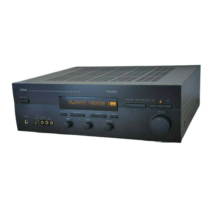
DIGITAL SOUND FIELD PROCESSING AMPLIFIER
P
-
A
P
-
A
7
8
7
8
NA TU
RA L
SO UN
D DIG
ITA L
SO UN
D FIE
LD PR
OC ES
SIN G
AM PLI
FIE R
DS P-A
78 0
2-4. SELECTING SOUND FIELD PROGRAMS............................................28
2-5. MUTING THE EFFECT SOUND ............................................................28
DISPLAY..................................................................................................28
2-7. DESCRIPTIONS OF THE SOUND FIELD PROGRAMS ......................29
CREATING YOUR OWN SOUND FIELDS ....................................................33
3-1. SELECTING AND EDITING PROGRAM PARAMETERS ....................33
PARAMETERS........................................................................................35
TROUBLESHOOTING ....................................................................................37
SPECIFICATIONS ...........................................................................................38
0
0
PRO
LOGI
C
DSP
Advertisement
Table of Contents

Related Manuals for Yamaha DSP -A780


Summary of Contents for Yamaha DSP -A780
-
Page 1: Table Of Contents
DIGITAL SOUND FIELD PROCESSING AMPLIFIER OPERATION MANUAL CONTENTS PRECAUTIONS & SAFETY INSTRUCTIONS ...Inside Front Cover SETUP & ADJUSTMENT...3 1-1. GETTING STARTED...3 1-2. SETUP ...8 1-3. CONTROLS & ADJUSTMENTS...16 1-4. ADJUSTMENT...20 GENERAL OPERATION...24 2-1. PLAYING A SOURCE ...24 2-2. RECORDING A SOURCE TO AUDIO/VIDEO TAPE (OR DUBBING FROM A TAPE TO ANOTHER)...25 2-3. -
Page 2: Precautions & Safety Instructions
PRECAUTIONS & SAFETY INSTRUCTIONS SAFETY INSTRUCTIONS Read Instructions – All the safety and operating instructions should be read CAUTION before the unit is operated. RISK OF ELECTRIC SHOCK DO NOT OPEN Retain Instructions – The safety and operating instructions should be retained CAUTION: TO REDUCE THE RISK OF for future reference. - Page 3 This product, when installed as indicated in the instructions contained in this manual, meets FCC requirements. Modifications not expressly approved by Yamaha may void your authority, granted by the FCC, to use the product. 2. IMPORTANT : When connecting this product to accessories and/or another product use only high quality shielded cables.
- Page 4 You are the proud owner of a Yamaha Digital Sound Field Processing (DSP) System—an extremely sophisticated audio component. The DSP system takes full advantage of Yamaha’s undisputed leadership in the field of digital audio processing to bring you a whole new world of listening experiences.
-
Page 5: Setup & Adjustment
SETUP & ADJUSTMENT 1-1. GETTING STARTED Unpacking If you haven’t already done so, carefully remove this unit and its accessories from the box and wrapping material. You should find the unit itself and the following accessories. Batteries Remote control Installing the Remote Control Unit Batteries Since the remote control unit will be used for many of this unit’s control operations, you should begin by installing the supplied batteries. - Page 6 Extensive research into the exact nature of the sonic reflections that create the ambience of a large hall has made it possible for Yamaha engineers to bring you this same sound in your own listening room, so you’ll feel all the sound of a live concert.
- Page 7 This combination is used on sound field programs No. 5 through No. 14, and No. 16. The YAMAHA “CINEMA DSP” logo indicates these programs created by the combination of Dolby Pro Logic and YAMAHA DSP technology. VIDEO SUPERIMPOSE If you connect your video cassette recorder, video disc player, video monitor, etc.
- Page 8 It is also possible to further expand your system with the addition of a subwoofer and amplifier. You may wish to choose the convenience of a Yamaha Active Servo Processing Subwoofer System, which has its own built-in power amp. 5 Speaker System...
- Page 9 SPEAKERS. (To avoid interference, keep the speaker above or below the television monitor, or use a magnetically shielded speaker.) If using a SUBWOOFER, such as a Yamaha Active Servo Subwoofer System, the position of the speaker is not so critical because low bass tones are not highly directional.
-
Page 10: Setup
1-2. SETUP Before you start making connections make sure all related electronic components are turned OFF. REAR PANEL (General Model) To AC outlet DUAL 10dB 0dB SINGLE SINGLE... - Page 11 Audio Signal Connection Jacks (for Audio Source Equipment) Connect the inputs and/or outputs of your audio equipment. Audio/Video Signal Connection Jacks (for Video Source Equipment) Connect the audio and video inputs and/or outputs of your video equipment. In place of the VIDEO jacks, the S VIDEO jacks can be used for higher resolution and improved picture quality if your VCR, monitor, etc.
- Page 12 GENERAL INSTRUCTIONS FOR CONNECTIONS Make sure that you have the left (L) and right (R) channels correctly connected. That means that jacks marked “L” on this unit must be connected to jacks marked “L” on other units. Likewise with the “R” jacks. This is easy if you remember to always use the red plug for the “R”...
- Page 13 CONNECTING TO S VIDEO JACKS If your video cassette recorder, video disc player, etc. and your monitor are equipped with “S” (high-resolution) video terminals, connect them to this unit’s S VIDEO jacks, and connect this unit’s S VIDEO MONITOR OUT jack to the “S” video input of your monitor. Otherwise, connect the composite video jacks from your video cassette recorder, video disc player, etc.
- Page 14 CONNECTING SPEAKER SYSTEMS Connect the SPEAKERS terminals to your speakers with wire of the proper gauge, cut as short as possible. If the connections are faulty, no sound will be heard from the speakers. Make sure that the polarity of the speaker wires is correct, that is, + and – markings are observed.
- Page 15 CONNECTING THE MAIN SPEAKERS AND THE REAR EFFECT SPEAKERS TO THIS UNIT Connect the MAIN speakers to the MAIN SPEAKERS terminals of this unit. Connect the REAR effect speakers to the REAR SPEAKERS terminals of this unit. Main speakers DUAL SINGLE SINGLE Rear effect speakers...
- Page 16 Connect the LOW PASS jack to the INPUT jack of the subwoofer amplifier, and connect the speaker terminals of the subwoofer amplifier to the subwoofer. With some subwoofers, including the Yamaha Active Servo Processing Subwoofer System, the amplifier and subwoofer are in the same unit.
- Page 17 ADDITIONAL INFORMATION ON CONNECTING SPEAKERS (for Europe, U.K. and Australia models) This unit is equipped with line output jacks for main, rear effect and center channels. If you will use an external power amplifier for driving main speakers, connect input jacks of the external power amplifier to the MAIN OUTPUT jacks of this unit.
-
Page 18: Controls & Adjustments
1-3. CONTROLS & ADJUSTMENTS FRONT PANEL NATURAL SOUND DIGITAL SOUND FIELD PROCESSING AMPLIFIER DSP-A780 Power Switch * STANDBY Mode (Europe model only) While the power is on, pressing the POWER key on the remote control unit switches the unit to the STANDBY mode. (In this mode, the indicator is half illuminated.) Remote control sensor Signals from the remote control unit are received here. - Page 19 PRO LOGIC Indicator Illuminates while the built-in Dolby Pro Logic Surround Decoder is being activated. DSP Indicator Illuminates while the built-in Sound Field Processor is being activated. Input Selector Switch Sequentially selects the input source that you want to listen to and/or watch in the direction.
- Page 20 * (Europe model only): Turns the POWER on mode to the STANDBY mode and vice versa. CD Function Keys Operate functions on Yamaha CD players designed for remote control compatibility. * DISC SKIP is applicable only to compact disc changer.
- Page 21 Select DSP program parameters or titles of settings/adjustments in the SET MENU mode, or used in the main/center/effect speaker level balance adjustment. Tuner Function Keys Operate functions on Yamaha tuners designed for remote control compatibility. +: Selects higher preset station number. –: Selects lower preset station number.
-
Page 22: Adjustment
1-4. ADJUSTMENT MAIN/CENTER/REAR EFFECT SPEAKER LEVEL BALANCE ADJUSTMENT This operation uses an internal test-tone generator for balancing the levels of the main, center and rear effect speakers. All speakers should be adjusted to the same apparent sound level for proper Dolby Pro Logic decoding. - Page 23 INPUT LEVEL ADJUSTMENT This adjustment is important for obtaining the best performance from the internal circuits of this unit. The optimum input level of this unit is pre-adjusted on the basis of the CD source level. This adjustment should be performed on all input sources in your system respectively, so that their levels match the CD source level as closely as possible.
- Page 24 OTHER IMPORTANT SETTINGS AND ADJUSTMENTS IN THE “SET MENU” MODE The following four types of settings and adjustments should be done before enjoying audio and video sources. Note that these settings and adjustments cannot be done without monitoring the display information (or the information displayed on the monitor screen).
- Page 25 3. Changing brightness of the display (DIMMER) You can select one of the five levels of brightness of the display. 4. Locking DSP parameters and other adjustments (MEMORY GUARD) If you wish to prevent accidental alteration to DSP parameters or other adjustments on this unit, select “ON”.
-
Page 26: General Operation
GENERAL OPERATION 2-1. PLAYING A SOURCE 1. Set the MASTER VOLUME control to minimum. Front panel 2. Turn the power on. Front panel POWER 3. Select an input source. (The selected source is shown by the display panel, the monitor screen and illumination of the corresponding indicator over the input selector switches.) Front panel... -
Page 27: Recording A Source To Audio/Video Tape (Or Dubbing From A Tape To Another)
2-2. RECORDING A SOURCE TO AUDIO/VIDEO TAPE (OR DUBBING FROM A TAPE TO ANOTHER) To record an input source to be played 1. Press the REC OUT switch (so that “REC OUT ... ” appears on the display and the monitor screen). Front panel 2. - Page 28 To record a source other than the input source to be played This unit has a function of selecting a source to be recorded to tape deck or VCRs independent of the selection of input source. 1. Press the REC OUT switch (so that “REC OUT ... ” appears on the display and the monitor screen).
- Page 29 NOTE: Adjusting the MASTER VOLUME, BASS, TREBLE controls, etc., or selecting a sound field program has no effect on the material being recorded. NOTE: Composite video and S video signals pass independently through this unit’s video circuits. Therefore, when recording or dubbing video signals between two video cassette recorders, if your source VCR is connected to provide only S video (or only composite video) signals, you can record only a S video (or only a composite...
-
Page 30: Digital Sound Field Programs
2-3. DIGITAL SOUND FIELD PROGRAMS This unit has 16 programs for digital sound field processing, 4 from actual acoustic environments from around the world, and 12 programs for Audio/Video sources including sources encoded with Dolby Pro Logic surround. Many of the programs contain various parameters that can be adjusted to the listener’s taste. -
Page 31: Descriptions Of The Sound Field Programs
2-7. DESCRIPTIONS OF THE SOUND FIELD PROGRAMS The following list gives brief descriptions of the sound fields produced by each of the DSP programs. Keep in mind that most of these are precise digital recreations of actual acoustic environments. The data for them was recorded at the locations described using sophisticated sound field measurement equipment. - Page 32 5. CONCERT VIDEO: This program produces an enthusiastic atmosphere and lets you feel that you are in the midst of the action, as if attending an actual jazz or rock concert. The indirect sound constituent spreads on the surround side of the sound field by the use of data of a large round hall for the surround side, so the image space around the screen and the sound space are fully expanded.
- Page 33 9. TV THEATER: The data of the sound field of a relatively narrow space is used for the front presence side. A moderately sized spatial sound field without excessive sound extension and reverberations gives reality to the characters in a drama. The data of the sound field of an opera house is used for the rear surround side.
- Page 34 Programs No. 13 through No. 16 reproduces video discs, video tapes and similar sources which are Dolby Surround encoded and bear the “DOLBY SURROUND” logo. 13. 70 mm MOVIE THEATER 1: This program is ideal for precisely reproducing the sound design of the newest movies.
-
Page 35: Creating Your Own Sound Fields
In each program, those parameters are preset with values precisely calculated by Yamaha to create the sound field unique for the program. It is recommended to use DSP programs without changing values of parameters, however, this unit also allows you to create your own sound fields. - Page 36 Each sound field program has a set of parameters that allow you to change the characteristics of the acoustic environment to create precisely the effect you want. These parameters correspond to the many natural acoustic factors that create the sound field you experience in an actual concert hall or other listening environment.
-
Page 37: Descriptions Of The Digital Sound Field Parameters
3-2. DESCRIPTIONS OF THE DIGITAL SOUND FIELD PARAMETERS Not all of the following parameters are found in every program. INIT DLY (Initial Delay) How it Affects the Sound: Changes the apparent distance from the source sound. Since the distance between a sound source and a reflective surface determines the delay between the direct sound and the first reflection, this parameter changes the location of the sound source within the acoustic environment. - Page 38 REV. TIME (Reverberation Time) How it Affects the Sound: The natural reverberation time of a room depends primarily on its size and the characteristics of its inner surfaces. This parameter, therefore, changes the apparent size of the acoustic environment over an extremely wide range. What it Does: Adjusts the amount of time it takes for the level of the dense, subsequent reverberation sound to decay by 60 dB (@ 1 kHz).
-
Page 39: Troubleshooting
TROUBLESHOOTING PROBLEM POSSIBLE CAUSE Power does not come on. AC cord not properly plugged in. Hum. Bad cable connection. No sound. Bad or incorrect input connection. Incorrect input source selection. No sound from the effect speakers. The EFFECT switch is set off. The DOLBY PRO LOGIC program is being used with material not encoded with Dolby Surround. -
Page 40: Specifications
Minimum RMS Output Power Per Channel Main (20 Hz – 20 kHz 0.015% THD 8Ω) [U.S.A. and Canada models] ... 65W+65W [Australia, Europe, U.K. and General models] ... 60W+60W Center (20 Hz – 20 kHz 0.015% THD 8Ω) [U.S.A. and Canada models] ... 65W [Australia, Europe, U.K. - Page 41 Video Section Video Signal Type [U.S.A. and Canada models] ... NTSC [Australia, Europe and U.K. models] ... PAL [General Model] ... NTSC/PAL Video Signal Level ... 1 Vp-p/75 S-Video Signal Level Y ... 1 Vp-p/75 C ... 0.286 Vp-p/75 Maximum Input Level ... More than 1.5 Vp-p Signal-to-Noise Ratio ...
- Page 42 YAMAHA ELECTRONICS (UK) LTD. YAMAHA HOUSE, 200 RICKMANSWORTH ROAD WATFORD, HERTS WD1 7JS, ENGLAND YAMAHA SCANDINAVIA A.B. J A WETTERGRENS GATA 1, BOX 30053, 400 43 VÄSTRA FRÖLUNDA, SWEDEN YAMAHA MUSIC AUSTRALIA PTY, LTD. 17-33 MARKET ST., SOUTH MELBOURNE, 3205 VIC., AUSTRALIA...