
Related Manuals for Toshiba MMU-AP0057MH-E


Summary of Contents for Toshiba MMU-AP0057MH-E
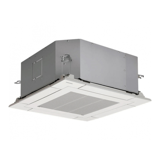
- Page 1 AIR CONDITIONER (MULTI TYPE) For commercial use Installation Manual Indoor Unit Model name: Compact 4-way Cassette type MMU-AP0057MH-E MMU-AP0127MH-E MMU-AP0077MH-E MMU-AP0157MH-E MMU-AP0097MH-E MMU-AP0187MH-E English...
-
Page 2: Table Of Contents
– 1 – Contents Original instruction Please read this Installation Manual carefully before installing the Air Conditioner. 1 Precautions for safety ..........3 •... - Page 3 Toshiba Carrier Corporation or, alternatively, he or she has been instructed in such matters by an individual or individuals who have been trained and is thus thoroughly acquainted with the knowledge related to this work.
-
Page 4: Precautions For Safety
– 3 – Precautions for safety Warning indications on the air conditioner unit The manufacturer shall not assume any liability for the damage caused Warning indication Description by not observing the description of this manual. WARNING WARNING WARNING ELECTRICAL SHOCK HAZARD ELECTRICAL SHOCK HAZARD General Disconnect all remote... - Page 5 • When work is performed at heights, use a ladder which complies with Installation the ISO 14122 standard, and follow the procedure in the ladder’s • When the indoor unit is to be suspended, the designated hanging instructions. Also wear a helmet for use in industry as protective gear bolts (M10 or W3/8) and nuts (M10 or W3/8) must be used.
- Page 6 – 5 – Electrical wiring • If there is any kind of trouble (such as check code display has • Only a qualified installer (*1) or qualified service person (*1) is appeared, smell of burning, abnormal sounds, the air conditioner fails allowed to carry out the electrical work of the air conditioner.
- Page 7 CAUTION R410A refrigerant air conditioner installation • This air conditioner adopts the HFC refrigerant (R410A) which does not destroy ozone layer. • The characteristics of R410A refrigerant are; easy to absorb water, oxidizing membrane or oil, and its pressure is approx. 1.6 times higher than that of refrigerant R22.
-
Page 8: Accessory Parts
– 7 – Accessory parts Selection of installation place Part name Shape Usage WARNING (Hand over to customers) Installation Manual This manual (For other languages that do not appear in this Installation Manual, • Install the air conditioner securely in a location where the base can sustain the weight adequately. please refer to the enclosed CD-R.) If the strength is not enough, the unit may fall down resulting in injury. - Page 9 Installation space Ceiling height Ensure there is sufficient space to install the unit and to perform maintenance work as and when required. Keep Unit : m 15 mm or more for clearance between top plate of the indoor unit and the ceiling surface. Model MMU- Installable ceiling height Unit: mm...
-
Page 10: Installation
– 9 – Installation External view Unit: mm Bottom face of ceiling REQUIREMENT Strictly comply with the following rules to prevent damage of the indoor units and human injury. • Do not put a heavy article on the indoor unit. (Even units are packaged) •... - Page 11 Opening a ceiling and Treatment of ceiling Installation of ceiling opening and For the grid ceiling, incline the unit and then mount the unit from the electrical control box side as shown in the hanging bolt The ceiling differs according to structure of building. installation of hanging bolts figure below.
-
Page 12: Drain Piping
– 11 – Drain piping Installation of ceiling panel Wireless remote controller (Sold separately) The sensor of indoor unit with wireless remote controller can receive a signal by distance within REQUIREMENT CAUTION CAUTION Install the ceiling panel according to Installation approx. - Page 13 Drain up Align the attached Drain pipe hose band to the end connecting When a down-gradient cannot be secured for the of hose, set the port VP20 vinyl chloride tightening position drainpipe, drain-up piping is possible. pipe upward, and then (Locally procured) Heat •...
-
Page 14: Refrigerant Piping
– 13 – Refrigerant piping Leak check test, evacuation Tightening connection and other procedure CAUTION CAUTION Refrigerant piping Permissible piping length and For leak check test, evacuation, addition of refrigerant, Do not apply excessive torque. Otherwise, the nut may and gas leak check, refer to the Installation Manual height difference crack depending on the conditions. -
Page 15: Electrical Connection
Electrical connection ▼ Power supply 220 V – 240 V ~, 50 Hz Power supply Power supply wire and 220 V ~, 60 Hz WARNING Power supply switch / circuit breaker or power supply wiring / fuse rating for indoor units should be selected by the communication wires accumulated total current values of the indoor units. - Page 16 – 15 – Wiring between indoor and outdoor units Wire connection NOTE REQUIREMENT An outdoor unit connected with control wiring between indoor and outdoor units wire becomes automatically the • Connect the wires matching the terminal numbers. Incorrect connection causes a trouble. •...
-
Page 17: Applicable Controls
Applicable controls Wiring on the ceiling panel CAUTION CAUTION According to the Installation Manual of the ceiling Basic procedure for changing *1 Make sure to fix the power supply wire with the cord panel, connect the louver motor connector on the REQUIREMENT clamp so that no water enters into the electrical settings... - Page 18 – 17 – When wireless remote Filter sign setting Specify CODE No. [ ] with temp. setup buttons. controller is used According to the installation condition, the lighting time Select SET DATA [ ] with timer time of the filter sign (Notification of filter cleaning) can be Change the high-ceiling setting with the DIP switch on buttons.
- Page 19 Selecting swing type Locking the louvers Cancelling louver lock • About “Dual swing” “Dual” means that louvers 01 and 03 are directed (No swing) 1. Push for 4 seconds or more when the air and swing in one direction and louvers 02 and 04 are Set the wind direction to “0000”...
-
Page 20: Test Run
– 19 – Test run Upon completion of the test run, push Precaution that the test run method in “ON/OFF” button to stop operation. wireless remote controller differs from <Overview of test run operations using the wireless other indoor units. remote controller>... -
Page 21: Maintenance
Maintenance Cleaning with water or vacuum cleaner. • If dirt is heavy, clean the air filter using tepid water with a neutral detergent or just water. <Daily maintenance> 3) Holding the air intake grille, slide the hook in • After cleaning with water, dry the air filter the direction of the arrow and slowly open the sufficiently in a shaded place. -
Page 22: Troubleshooting
– 21 – Troubleshooting ▼ Periodic Maintenance • For environmental conservation, it is strongly recommended that the indoor and outdoor units of the air conditioner in use be cleaned and maintained regularly to ensure efficient operation of the air conditioner. When the air conditioner is operated for a long time, periodic maintenance (once a year) is recommended. - Page 23 Check method (The following check code table explain in SMMS-e.) On the wired remote controller, central control remote controller and the interface P.C. board of the outdoor unit (I/F), a check display LCD (Remote controller) or 7-segment display (on the outdoor interface P.C. board) to display the operation is provided.
- Page 24 – 23 – Check code Wireless remote controller Outdoor unit 7-segment display Sensor block display of receiving unit Check code name Judging device Wired remote controller display Auxiliary code Operation Timer Ready Flash — — Indoor unit TCJ sensor trouble Indoor unit —...
- Page 25 Check code Wireless remote controller Outdoor unit 7-segment display Sensor block display of receiving unit Check code name Judging device Wired remote controller display Auxiliary code Operation Timer Ready Flash — Outdoor unit capacity unset — Outdoor unit type mismatch trouble —...
- Page 26 I/F Differs according to trouble contents of unit with occurrence of alarm Group control follower unit trouble TCC-LINK — — (L20 is displayed.) Duplication addresses of indoor units in ТСС-LINK central control device TCC-LINK: TOSHIBA Carrier Communication Link. 49-EN 50-EN...
-
Page 27: Specifications
Main unit (Ceiling panel) 336 Tadehara, Fuji-shi, Shizuoka-ken 416-8521 JAPAN Cooling Heating MMU-AP0057MH-E 15 (2.5) MMU-AP0077MH-E 15 (2.5) TCF holder: TOSHIBA CARRIER EUROPE S.A.S Route de Thil MMU-AP0097MH-E 15 (2.5) 01120 Montluel FRANCE MMU-AP0127MH-E 15 (2.5) MMU-AP0157MH-E 15 (2.5) Hereby declares that the machinery described below: MMU-AP0187MH-E 15 (2.5) - Page 28 – 27 – 53-EN 54-EN...
- Page 29 EB99813301...