Toshiba MMU-AP0071MH Service Manual
Compact 4-way air discharge cassette type
Hide thumbs
Also See for MMU-AP0071MH:
- Owner's manual (230 pages) ,
- Installation manual (145 pages) ,
- Installation manual (32 pages)
Table of Contents
Advertisement
Quick Links
<Compact 4-Way Air Discharge Cassette Type>
MMU-AP0071MH
MMU-AP0091MH
MMU-AP0121MH
MMU-AP0151MH
MMU-AP0181MH
• This Service Manual describes contents of the Compact 4-Way Air Discharge Cassette indoor unit.
For the outdoor unit, refer to the Manual with FILE No. A03-009, A05-004, A05-015.
PRINTED IN JAPAN, Apr., 2006 ToMo
Advertisement
Table of Contents

Related Manuals for Toshiba MMU-AP0071MH


Summary of Contents for Toshiba MMU-AP0071MH
- Page 1 <Compact 4-Way Air Discharge Cassette Type> MMU-AP0071MH MMU-AP0091MH MMU-AP0121MH MMU-AP0151MH MMU-AP0181MH • This Service Manual describes contents of the Compact 4-Way Air Discharge Cassette indoor unit. For the outdoor unit, refer to the Manual with FILE No. A03-009, A05-004, A05-015.
-
Page 2: Table Of Contents
SAFETY CAUTION ... 3 1. CONSTRUCTION VIEWS (EXTERNAL VIEWS) ... 8 2. WIRING DIAGRAM ... 9 3. PARTS RATING ... 10 4. REFRIGERATING CYCLE DIAGRAM ... 34 5. CONTROL OUTLINE ... 35 6. APPLIED CONTROL ... 39 7. TROUBLESHOOTING ... 44 8. -
Page 3: Safety Caution
SAFETY CAUTION The important contents concerned to the safety are described on the product itself and on this Service Manual. Please read this Service Manual after understanding the described items thoroughly in the following contents, and keep them. Before troubleshooting or repair work, check the earth wire is connected to the earth terminals of the main unit, otherwise an electric shock is caused when a leak occurs. - Page 4 WARNING After repair work, surely assemble the disassembled parts, and connect and lead the removed cables as before. Perform the work so that the cabinet or panel does not catch the inner cables. If incorrect assembly or incorrect cable connection was done, a disaster such as a leak or Assembly/Cabling fire is caused at user’s side.
- Page 5 • New Refrigerant (R410A) This air conditioner adopts a new HFC type refrigerant (R410A) which does not deplete the ozone layer. 1. Safety Caution Concerned to New Refrigerant The pressure of R410A is high 1.6 times of that of the former refrigerant (R22). Accompanied with change of refrigerant, the refrigerating oil has been also changed.
- Page 6 4. Tools (1) Required Tools for R410A Mixing of different types of oil may cause a trouble such as generation of sludge, clogging of capillary, etc. Accordingly, the tools to be used are classified into the following three types. 1) Tools exclusive for R410A (Those which cannot be used for conventional refrigerant (R22)) 2) Tools exclusive for R410A, but can be also used for conventional refrigerant (R22) 3) Tools commonly used for R410A and for conventional refrigerant (R22) The table below shows the tools exclusive for R410A and their interchangeability.
- Page 7 5. Recharge of Refrigerant When recharge of the refrigerant is required, charge the new refrigerant with the specified amount in the procedure as described below. Recover the refrigerant and check there is no refrigerant in the equipment. Connect the charge hose to the packed valve service ports at gas side, liquid side, and balance side of the outdoor unit.
-
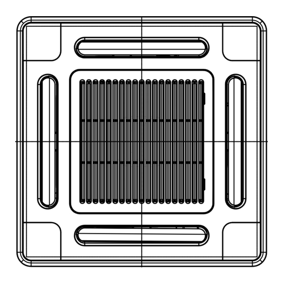
Page 8: Construction Views (External Views)
1. CONSTRUCTION VIEWS (EXTERNAL VIEWS) 595 to 660 Ceiling open dimension 1000 or more Obustacle 1000 or more Space required for installation and servicing Knockout for fresh air intake Ø100 145.5 700 Panel external dimension Bottom face 595 to 660 Ceiling open dimension of ceiling Ø162 (Pitch) Electric parts box... -
Page 9: Wiring Diagram
2. WIRING DIAGRAM 6 4 3 1 2 5 6 4 3 1 2 5 1 2 3 4 5 6 1 2 3 4 5 6 CN333 CN82 (BLU) (WHI) CN334 (WHI) CN68 (BLU) RY302 CN304 RY303 (GRY) Fuse CN67 T6.3A (BLK) -
Page 10: Parts Rating
3. PARTS RATING 3-1. Parts Rating Model MMU- AP0071MH Fan motor Motor for horizontal grille Pulse motor Pulse motor valve TA sensor TC1 sensor TC2 sensor TCJ sensor Float switch Drain pump motor 3-2. Name of Each Part Earth screw It is included in the electric parts box. - Page 11 3-3. Parts Name of Remote Controller Display section In the display example, all indicators are displayed for the explanation. In reality only, the selected contents are indicated. • When turning on the leak breaker at the first time, [SET DATA] flashes on the display part of the remote controller.
- Page 12 Operation section Push each button to select a desired operation. This remote controller can operate the maximum 8 indoor units. • The details of the operation needs to be set up once, afterward, the air conditioner can be used by pushing ON / OFF button only.
- Page 13 3-4. Correct Usage When you use the air conditioner for the first time or when you change the SET DATA value, follow the proce- dure below. From the next time, the operation displayed on the remote controller will start by pushing the ON / OFF button only.
- Page 14 3-5. Automatic Operation (Super Heat Recovery Type Only) When you set the air conditioner in change, it will automatically select either cooling, heating, or fan only operation depending on the indoor tem- perature. Start ON / OFF button Push this button to start the air conditioner. Mode select button (MODE) Select Auto.
- Page 15 3-6. TIMER Operation A type of timer operation can be selected from the following three types. OFF timer : The operation stops when the time of timer has reached the set time. Repeat OFF timer : Every time, the operation stops after the set time has passed. ON timer : The operation starts when the time of timer has reached the set time.
- Page 16 3-7. Adjustment of Wind Direction • While the air conditioner stops, the horizontal flap (Up/Down air direction adjustment plate) automati- cally directs upward. • While the air conditioner is in ready status for heating, the horizontal flap (Up/Down air direction adjustment plate) directs upward.
- Page 17 3-8. Information Confirmation before operation • Turn on the power switch 12 hours before starting the operation. • Make sure whether earth wire is connected. • Make sure the air filter is connected to the indoor unit. Heating capacity • A heat pump system which absorbs heat from outside of the room and then discharges heat into the room is adopted for heating.
- Page 18 3-9. Air Conditioner Operations and Performance 3 minutes protection function 3-minutes protection function prevents the air conditioner from starting for initial 3 minutes after the main power switch/circuit breaker is turned on for re-starting the air conditioner. Power failure Power failure during operation will stop the unit completely. •...
- Page 19 3-10. When the Following Symptoms are Found Check the points described below before asking repair servicing. Symptom Outdoor unit • White misty cold air or water is out. • Sometimes, noise “Pushu !” is heard. Indoor unit • “Swish” sound is heard sometimes.
- Page 20 Accessory parts and Parts to be procured locally H Accessory parts Part name Q’ty Shape Installation Manual This manual (Ensure hand over to customer) Heat insulating pipe For heat insulation of the pipe connecting section Installation pattern —— For checking of ceiling opening and the main unit position For positioning of the ceiling position Installation gauge (To be used with the installation pattern)
- Page 21 PRECAUTIONS FOR SAFETY • Install the air conditioner securely in a location where the base can sustain the weight of the unit adequately. • Perform the specified installation work to guard against an earthquake. If the air conditioner is not installed appropriately, accidents may occur due to the unit falling. •...
- Page 22 SELECTION OF INSTALLATION PLACE In case of wireless type The wireless remote controller can be operated up to a maximum of 8 m from the infra-red receiver. Therefore ensure that the remote controller will be mounted and used within this stated parameter. •...
- Page 23 INSTALLATION OF INDOOR UNIT Ceiling opening and installation of hanging bolts • Evaluate and determine the piping and wiring requirements inside the ceiling prior to the hanging of the unit. • After installation place of the indoor unit has been determined, create opening in ceiling and install the hanging bolts.
- Page 24 DRAIN PIPING WORK CAUTION Pipe material/Insulator and size The following materials for piping work and insulation • Install the drain piping so that the water are to be procured locally. drains effectively. • Apply heat insulation to prevent dew condensation from forming. Pipe material •...
- Page 25 DRAIN PIPING WORK Thermal insulating process • After checking of the draining, using the supplied thermal insulation fit to the flexible hose leaving no clearance at the connecting port of the indoor unit. • Fit locally procured thermal insulation to the drain pipe leaving no clearance between the supplied insulation. Flexible hose Hose band Ensure water is poured slowly.
- Page 26 REFRIGERANT PIPING • Projection margin in flaring : Airtight test/Air purge, etc. B (Unit : mm) For carrying out airtight test, air purge, gas leak check and addition of refrigerant refer to the Installation Manual supplied with the outdoor unit. Rigid (Clutch type) R410A tool used Conventional tool used...
- Page 27 ELECTRIC WORK Power supply specifications Power supply wiring and communication wiring are to be procured locally. For the power supply specification, follow the table below. Ensure power supply is adequate. An insufficient power supply could result in unit failure. For specification of the power capacity of the outdoor unit and the power supply wires, refer to the Installation Manual supplied with the outdoor unit.
- Page 28 ELECTRIC WORK Remote controller wiring • Strip approximately 14 mm of insulation off of the connecting wires. • As the remote controller wire has no polarity, there is no problem if connections to indoor unit terminal blocks A and B are reversed. Wiring diagram Terminal block for remote controller Terminal block...
- Page 29 APPLICABLE CONTROLS In case of installation to high ceiling When the unit is to be installed at a height that exceeds the standard value, adjustment to the air volume is necessary. • For the “Setup data” in Procedure 2 , select from the “Installable ceiling height list”. Installable ceiling height list Indoor unit capacity type 0071 to 0121 type...
- Page 30 TEST RUN Before test operation • Before turning on the power supply, carry out the following procedures. 1) Using 500V-megger, check there is 1M or more between the terminal block of the power supply and the earth. If 1M or less is detected, do not run the unit. 2) Check that all the valves of the outdoor unit are fully opened.
- Page 31 TROUBLESHOOTING Confirmation and check When a fault occurs in the air conditioner, the check code and the indoor unit No. will appear on the display part of the remote controller. The check code will only be displayed while the unit is in operation.
- Page 32 — Indoor, I/F Differs according to error contents of unit with occurrence of alarm Indoor — Indoor Terminology TCC-LINK : TOSHIBA Carrier Communication Link. Indoor Wireless remote controller Sensor block display Check code name of receiving unit Auxiliary code Operation...
- Page 33 TROUBLESHOOTING New check code 1. Difference between the new check code and the current system The displaying method of the check code will change from this model onwards. New check code Used characters Alphabet + Decimal notation, 2 digits Characteristics of code classification Many classification of communication/incorrect setup system Communication/Incorrect setup (4-ways), Indoor protection, Outdoor protection, Block display...
-
Page 34: Refrigerating Cycle Diagram
4. REFRIGERATING CYCLE DIAGRAM Liquid side Gas side Strainer Capillary tube Pulse Motor Valve (PMV) Strainer Sensor (TC2) Functional part name Pulse Motor Valve Temp. sensor Air heat exchanger at indoor side Sensor (TCJ) Sensor (TA) Functional outline (Connector CN082 (6P): Blue) 1) Controls super heat in cooling operation 2) Controls under cool in heating operation 3) Recovers refrigerant oil in cooling operation... -
Page 35: Control Outline
5. CONTROL OUTLINE 5-1. Control Specifications Item Power supply 1. Distinction of outdoor unit is reset. When the power supply is reset, the outdoor units are distinguished, and control is exchanged according to the distinctive results. 2. Check code clear When the power supply is reset, the check code is also reset once. - Page 36 Item Prevention of 1. In all heating operation, the upper limit of the fan tap is set by cold air one with higher temperature of TC2 sensor and TCJ sensor. discharge • When B zone has continued for 6 minutes, the operation shifts to C zone.
- Page 37 Item Recovery control 1. The indoor unit which stops operation, thermostat is OFF, for cooling or operates in FAN mode opens PMV of the indoor unit by refrigerant and oil the specified opening degree when cooling refrigerant or oil recovery signal is received from the outdoor unit. 2.
- Page 38 Item “ ” and “ ” <Operation standby> ... Display on remote controller display 1. • “P05” is one of displays of power wire missing. (Operation and • “P05” of power cable is detected. heating stand-by) • “COOL/DRY” operation cannot be performed because the other indoor unit is under “HEAT”...
-
Page 39: Applied Control
6. APPLIED CONTROL 6-1. Setup of Selecting Function in Indoor Unit (Be sure to Execute Setup by a Wired Remote Controller) <Procedure> Execute the setup operation while the unit stops. TEST Push , and buttons simultaneously for 4 seconds or more. The firstly displayed unit No. - Page 40 Table: Function selecting item numbers (DN) (Items necessary to perform the applied control at the local site are described.) Item Filter display delay timer 0000 : None 0002 : 2500H 0004 : 10000H Dirty state of filter 0000 : Standard 0001 : High degree of dirt (Half of standard time) Central control address 0001 : No.1 unit...
- Page 41 TYPE Item code [10] Setup Type data 0014 Compact 4-way Air Discharge Cassette 6-2. Applied Control in Indoor Unit n Remote location ON/OFF control box (TCB-IFCB-4E) [Wiring and setup] • Use the exclusive connector for connection with the indoor control P .C. board. •...
- Page 42 n Ventilating fan control from remote controller [Function] • The start/stop operation can be operated from the wired remote controller when air to air heat exchanger or ventilating fan is installed in the system. • The fan can be operated even if the indoor unit is not operating. •...
- Page 43 n Leaving-ON prevention control [Function] • This function controls the indoor units individually. It is connected with cable to the control P .C. board of the indoor unit. • In a group control, it is connected with cable to the indoor unit (Control P .C. board), and the item code set to the connected indoor unit.
-
Page 44: Troubleshooting
7. TROUBLESHOOTING 7-1. Troubleshooting Summary 1. Before troubleshooting 1) Applied models S-MMS Multi type models Indoor unit: MMX-APXXX, Outdoor unit: MMY-MAPXXXHT8, MMY-MAPXXXT7 Super Heat Recovery Multi type models Indoor unit: MMX-APXXX, Outdoor unit: MMY-MAPXXXFT8 Mini-S-MMS Multi type models Indoor unit: MMX-APXXX, Outdoor unit: MCY-MAPXXXHT, MCY-MAPXXXHT2D 2) Required tools / measuring devices •... - Page 45 7-2. Check Method On the remote controller (Main remote controller, Central control remote controller) and the interface P .C. board of the outdoor unit, a check display LCD (Remote controller) or 7-segment display (on the outdoor interface P .C. board) to display the operation is provided. Therefore the operation status can be known. Using this self-diagno- sis function, a trouble or position with trouble of the air conditioner can be found as shown in the table below.
- Page 46 Check code Main Outdoor 7-segment display remote controller display Auxiliary code — — — — — — — — — — — — — — 01: Comp. 1 side 02: Comp. 2 side — — — — — — — 01: Comp.
- Page 47 Check code Main Outdoor 7-segment display remote controller display Auxiliary code — — — 01: Comp. 1 side 02: Comp. 2 side 01: Phase-missing detection 02: Phase error 01: Comp. 1 side 02: Comp. 2 side P10 Detected indoor address —...
- Page 48 The check code 1. The TCC LINK check code The displaying method of the check code. Alphabet + Decimal notation, 2 digits Used characters Characteristics of Many classification of communication/ code classification incorrect setup system Communication/Incorrect setup (4 ways), Block display Indoor protection, Outdoor protection, Sensor, Compressor protection, etc.
- Page 49 7-3. Troubleshooting by Check Display on Remote Controller In case of wired remote controller (RBC-AMT31E) 1. Confirmation and check When a trouble occurred on the air conditioner, the check code and the indoor unit No. are displayed on the display section of the remote controller.
- Page 50 In case of central remote controller (TCB-SC642TLE) 1. Confirmation and check When a trouble occurred on the air conditioner, the check code and the indoor unit No. are displayed on the display section of the remote controller. The check code is displayed while the air conditioner operates. If the display disappeared, operate the air conditioner and check the error based upon the following “Confir- mation of error history”.
-
Page 51: Check Code And Check Position (7-Segment Display Of Interface)
7-4. Check Code and Check Position Displayed on the Remote Controller and Outdoor Unit (7-Segment Display of Interface) Check code Detected Main Outdoor 7-segment display position remote controller Check code Auxiliary code Remote Communication error between — — controller indoor and remote controller (Detected at remote controller side) —... - Page 52 Check code Detected Main Outdoor 7-segment display position remote Check code Auxiliary code controller 01: Indoor/outdoor communication 02: Between outdoors communication — 00: Capacity over 01 to: No. of connected units — — Indoor 00: No header unit 02: Two or more header units 01: Connection of outdoor of other line 02: Connection of indoor of other line —...
- Page 53 Check code Main Outdoor 7-segment display remote Check code Auxiliary code controller 01: IPDU1 error 02: IPDU2 error 03: IPDU1, 2 errors 04: Fan IPDU error 05: IPDU1 + Fan IPDU error 06: IPDU2 + Fan IPDU error 07: All IPDU error or communication error between IPDU and I/F P .C.
- Page 54 Check code Detected Main Outdoor 7-segment display position remote Check code Auxiliary code controller 01: Compressor 1 side IPDU TH sensor error 02: Compressor 2 side — Outdoor temp sensor miscabling (TE1, TL) — Outdoor pressure sensor miscabling (Pd, Ps) —...
- Page 55 Check code Detected Outdoor 7-segment display Main position remote controller Check code Auxiliary code 01: Compressor 1 side IPDU 02: Compressor 2 side — — Check code name Status Error detection condition Current detection All stop While header compressor stopped, current flowed circuit system error more than the specified current and was detected.
- Page 56 Check code Detected Main Outdoor 7-segment display Check code name position remote Check code Auxiliary code controller — Protection for oil level drop detection 01: TK1 sensor error Oil level detective temp sensor error 02: TK2 sensor error 03: TK3 sensor error 04: TK4 sensor error —...
- Page 57 Check code Detected Main Outdoor 7-segment display position remote Check code Auxiliary code controller 01: TK1 oil circuit system error 02: TK2 oil circuit system error 03: TK3 oil circuit system error 04: TK4 oil circuit system error — — Indoor —...
- Page 58 Check code Main Outdoor 7-segment display remote Check code Auxiliary code controller No. of indoor units with priority — — — — — — — Corresponding indoor address — — — 01: IPDU1 error 02: IPDU2 error 03: IPDU1, 2 errors 04: Fan IPDU error 05: IPDU1 + Fan IPDU error 06: IPDU2 + Fan IPDU error...
- Page 59 Check code Detected Main Outdoor 7-segment display position remote Check code Auxiliary code controller — — Indoor — 01: Compressor 1 side 02: Compressor 2 side 01: Power supply open phase 02: Power supply negative phase Check code name Status Error detection condition Indoor fan motor error Corresponding...
- Page 60 Check code Detected Main Outdoor 7-segment display Check code position remote Check code Auxiliary code controller 01: Compressor 1 side IPDU Heat sink overheat error 02: Compressor 2 side Indoor address with Indoor Indoor overflow trouble error — — Indoor Indoor fan motor error —...
- Page 61 Check code Detected Main Outdoor 7-segment display Check code name position remote Check code Auxiliary code controller — Discharge temp TD2 error Detected outdoor unit No. 4-way valve operation error — High-pressure protective operation Status Error detection condition All stop Discharge temperature (TD2) •...
- Page 62 Check code Detected Outdoor 7-segment display Main position remote controller Check code Auxiliary code 0: IGBT shortage FAN-IPDU 1: Position detection circuit error 3: Motor lock error 4: Motor current error detection C: TH sensor temp. error D: TH sensor error E: Vdc error 01: Compressor 1 side IPDU...
- Page 63 Error detected by TCC-LINK central control device Check code Outdoor 7-segment display Display on central control device Check code Auxiliary code — — — Differs according to error contents of the with alarm (L20 is displayed.) Detected position Check code name Status Error detection condition TCC-LINK...
- Page 64 Cautions when servicing for compressor 1. Removing wires of both compressors check output of the inverter as described below. How to check inverter output 1. Turn off the power supply. 2. Remove the compressor lead cables from the compressors. (Be sure to remove lead cables of both compressors.) 3.
- Page 65 7-5. Diagnosis Procedure for Each Check Code Check code Check code name [E01] Communication error between 1. Remote controller inter-unit cable error indoor and remote controller 2. Indoor power error (Detected at remote controller side) 3. Indoor P.C. board error 4.
- Page 66 Check code Check code name [E06] Decreased number of indoor units 1. Communication lines (U1, U2) connection error between indoor and outdoor 2. Connector connection error of communica- tion for indoor P.C. board 3. Connector connection error of communica- tion for outdoor I/F board 4.
- Page 67 Check code Check code name [E08] Duplicated indoor addresses Indoor addresses are duplicated. Auxiliary code : Duplicated indoor address Using a main remote controller (RBC-AMT21E), check the setup item codes (DN code) 12, 13, and 14. When there is no address duplication, check to the following flowchart. Is cable connection to communication line normal? Is not communication line connected...
- Page 68 Check code Check code name [E16] Connected indoor units 1. There are 48 or more connected indoor units. capacity over 2. Capacity over of total connected indoor units. 3. Incorrect setup of indoor/outdoor capacity Auxiliary code : 00 : Capacity over 01 : ~ : Number of connected indoor units Is backup operation of outdoor unit being set up? Is No.
- Page 69 Check code Check code name [E20] Unit connected to other line When starting automatic indoor address, a during automatic address device in other line is connected. Auxiliary code : 01: Connection of outdoor in other line 02: Connection of indoor unit in other line Separate the wire between lines according to address setup method.
- Page 70 Check code Check code name [E31] IPDU communication error 1. Connection error of communication line between IPDU and I/F P.C. board 2. I/F P.C. board error 3. IPDU P.C. board error 4. External noise Auxiliary code : 01: IPDU1 error 02: IPDU2 error 03: IPDU1, 2 error 04: Fan IPDU error...
- Page 71 Check code Check code name [F04] TD1 sensor error TD1 sensor Open/Short This error code means detection of Open/Short of TD1 sensor. Check disconnection of circuit for connection of connector (TD1 sensor: CN502, White) and characteristics of sensor resistance value. (Refer to Outdoor unit temperature sensor characteristics.) If sensor is normal, replace outdoor I/F P.C.
- Page 72 Check code name Check code name [F15] Outdoor temp sensor miscabling 1. Misinstallation and misconnection of TE1 (TE1, TL) 2. Resistance characteristics error of TE1 3. Outdoor P.C. board (I/F) error Are installed positions of TE1 sensor and TL sensor correct? Outdoor I/F P.C.
- Page 73 Check code name Check code name [F31] Outdoor EEPROM error 1. Outdoor unit power error (Voltage, noise, etc.) 2. Outdoor I/F P.C. board error Is there any trouble of outdoor unit power supply? Check I/F P.C. board. Check code name Check code name [H01] Compressor breakdown...
- Page 74 Check code name Check code name [H04] Compressor 1 case thermo operation 1. Case thermo circuit error 2. I/F P.C. board error [H14] Compressor 2 case thermo operation 3. Service valve closed 4. Outdoor PMV clogging 5. SV4 valve leak, Coil misinstallation 6.
- Page 75 Check code name Check code name [H07] Oil level down 1. Valves of balance pipes closed. detection protection 2. Miscabling or misinstallation of TK1 to TK4 sensors 3. TK1 to TK4 sensor error 4. Gas leak or oil leak of all outdoor units 5.
- Page 76 (*3) Check for solenoid valve of outdoor unit (For multiple outdoor unit system) a) Clogging check for SV3A valve • While outdoor unit is operating, set up SW01/02/03 = [2] [1] [3] to 7-segment display [Hr] [ 2], and push SW04 for 2 seconds or more.
- Page 77 Check code name Check code name [H16] Oil level detective circuit system error (Auxiliary code : 02) Is not TK2 sensor detached? Is there no miscabling or misinstallation on TK1/TK2/TK3/TK4 sensors? Are characteristics of TK2 sensor resistance value normal? Outdoor unit temp sensor characteristics-4 Does OCR of MG-SW operate? After power reset Start a test operation in COOL or HEAT mode.
- Page 78 Check code name Check code name [H16] TK4 temperature detective circuit error (Auxiliary code : 04) Is not TK4 sensor detached? Is there no miscabling or misinstallation on TK1/TK2/TK3/TK4 sensors? Are characteristics of TK4 sensor resistance value normal? Does OCR of MG-SW operate? No error Check the clogging of SV3E valve.
- Page 79 Check code name Check code name [L07] Group line in individual indoor unit Check setup item code Is there group cabling? DN 12, 13, and 14 addresses. There is individual indoor unit. ® Check indoor P.C. board. Failure Replace Check code name Check code name [L08] Indoor group / address unset...
- Page 80 Check code name Check code name [L18] Flow selector unit system error An indoor unit which has been operated in cooling only mode is operated in heating mode without setup for cooling only mode. Did set up All cooling to All cooling indoor unit? Check code name Check code name [L20]...
- Page 81 Check code name Check code name [L30] Interlock in indoor unit Outside error was input. from outside Is outside device connected to connector CN80? Does outside device correctly operate? Check cause of the operation. Check code name Check code name [L31] Extended IC error 1.
- Page 82 Check code name Check code name [P04] Actuation of 1. High-pressure SW error high-pressure SW 2. Service valve closed 3. Pd sensor error 4. Indoor/outdoor fan error 5. Indoor/outdoor PMV choke 6. Indoor/outdoor heat exchanger clogging, air short circuit 7. SV2 circuit error 8.
- Page 83 Check code name Check code name [P07] Heat sink overheat error 1. Power voltage error 2. Outdoor fan system error 3. Heat sink installation error 4. Clogging of hear sink cooling duct 5. IPDU P.C. board error (TH sensor error) Auxiliary code : 01: Compressor 1 side 02: Compressor 2 side Is power voltage normal?* * 380–415V ±...
- Page 84 Check code name Check code name [P13] Outdoor liquid back detection error 1. PMV1/PMV2 error 2. Pd sensor, Ps sensor error 3. Clogging of SV2 circuit 4. Clogging of SV3B circuit, balance pipe 5. Leakage of main discharge pipe 6. Outdoor I/F P.C. board error Are connections of outdoor PMV1/PMV2 connectors correct? Are operations of outdoor...
- Page 85 Check code name Check code name [P15] Gas leak detection 1. Outdoor unit service valve closed TD condition (Auxiliary code : 02) 2. Outdoor PMV error 3. TD sensor error 4. SV4 circuit error 5. Refrigerant shortage, clogging refrigerant circuit Are service valves of gas and liquid sides fully opened? Is outdoor PMV1, 2 normal?
- Page 86 Check code name Check code name [P19] 4-way valve operation error 1. 4-way valve error 2. TS1 sensor/TE1 sensor error 3. Pd sensor/Ps sensor error 4. TE sensor/TL sensor misconnection Auxiliary code : Detected outdoor unit No. Is 4-way valve coil connector connected? Are TS1, TE1, Pd, Ps sensor connectors connected?
- Page 87 All heating operation Is connector connection of indoor Does heating indoor fan normally operate? heat exchanger fan or fan motor normal? Is indoor PMV normal? Are characteristics Is connector connection of sensor TC2 and TCJ coil normal? resistance normal? Repair faulty parts. Check indoor P.C.
- Page 88 Check code name Check code name [P26] G-Tr short-circuit protection error 1. Outdoor unit power error 2. IPDU error/Cable connection error 3. Compressor error 4. IPDU P.C. board error Auxiliary code : 01: Compressor 1 side 02: Compressor 2 side Is power voltage of outdoor unit normal? Is wire connector connection on IPDU P.C.
- Page 89 7-6. 7-Segment Display Function n 7-segment display on the outdoor unit (Interface P.C. board) On the interface control P .C. board, 7-segment LED to check the operating status is provided on the control P .C. board. The displayed contents are changed by combining the setup numbers of the rotary switches (SW01, SW02, and SW03) on P .C.
- Page 90 1. Data display of system information (Displayed on the header outdoor unit only) SW01 SW02 SW03 Refrigerant name System capacity No. of outdoor units No. of connected indoor units/ No. of units with cooling thermo ON No. of connected indoor units/ No.
- Page 91 2. Data display of outdoor unit information (Displayed on each outdoor unit) SW01 SW02 SW03 Error data — Operation mode Outdoor unit HP Compressor operation command Outdoor fan step Compressor backup — Control valve output data PMV1 /PMV2 opening — Oil level judgment status Display contents Displays outdoor unit number: [U1] to [U4]...
- Page 92 3. Data display of outdoor cycle (Displayed on each outdoor unit) SW01 SW02 SW03 Pd pressure data Ps pressure data PL pressure conversion data Estimated pressure of liquid line (MPaG) is displayed with decimal data. TD1 sensor data TD2 sensor data TS1 sensor data TS2 sensor data TE sensor data...
- Page 93 5. Outdoor EEPROM write-in error code display (Displayed on the header unit only) The latest error code written in EEPROM of each outdoor unit is displayed. (It is used when confirming the error code after power supply has been reset.) Set SW01 to 03 as shown in the following table, and the push SW04 for 5 seconds or more to display an error code.
-
Page 94: Configuration Of Control Circuit
Indoor unit Network adaptor (Option) Indoor control P.C. board (MCC-1402) Network Remote adaptor controller P.C. board communication (MCC-1401) circuit DC5V H8/3687 DC12V DC5V Power circuit Switch setup Transformer Louver TMP88CH motor 47FG (TMP88PH47FG) None for Concealed Duct type Drain Fan motor pump control circuit Power... - Page 95 Indoor unit Network adaptor (Option) Indoor control P.C. board (MCC-1402) Network Remote adaptor controller P.C. board communication (MCC-1401) circuit DC5V H8/3687 DC5V Power Switch DC12V circuit setup Transformer Louver motor None for Concealed Duct type Drain TMP88CH pump 47FG (TMP88PH47FG) Indoor Fan motor fan motor...
- Page 96 Indoor unit Network adaptor (Option) Indoor control P.C. board (MCC-1402) Network adaptor Remote P.C. board controller (MCC-1401) communication circuit DC5V H8/3687 Power circuit Switch setup Transformer Louver motor None for Concealed Duct type Drain (TMP88PH47FG) pump Indoor fan motor Power circuit 280V Max.
- Page 97 Microcomputer operation LED DC fan output PMV output DC fan return Float SW Fan output HA (T10) TA sensor Optional output Flap (Used only for 4-way Air Discharge Cassette Type,Under ceiling type) Filter/Option error input EEPROM TCJ sensor EXCT Remote controller inter-unit cable TC1 sensor Used for DISP...
- Page 98 8-1-3. Optional Connector Specifications of Indoor P.C. Board Connector Function Humidifier output CN66 Fan output CN32 — CN61 Option output CN60 Outside error input CN80 — CN20 — CN70 CHK operation check CN71 DISP exhibition mode CN72 EXCT demand CN73 Specifications ...
-
Page 99: Detachments
9. DETACHMENTS 9-1. Indoor Unit MMU-AP0071MH, AP0091MH, AP0121MH, AP0151MH, AP0181MH Ceiling panel: RBC-UM11PG-E Preparing work: 1. Before work, be sure to stop the power supply of the air conditioner and turn off switch of the power supply breaker. (Otherwise an electric shock may be caused.) 2. - Page 100 Part name Adjust 1. Detachment corner cover 1) Perform work of procedure of 2) Turn clockwise screws (4 positions) at the suction port corner until adjust corner cover rises up. NOTE) When you work, keep the torque at below 12N•m. Do not use an electric screwdriver;...
- Page 101 Part name 1. Detachment Control P.C. board 1) Perform works of procedure 2) Remove the connectors connected from the control P.C. board to other parts. CN33 : Flap motor (5P, White) CN34 : Float switch (3P, Red) CN41 : Terminal block of remote controller (3P, Blue) CN40 : Terminal block of crossover between inside and outside (2P, Blue) CN68 : Drain pump (3P, Blue) CN67 : Terminal block of power supply (3P, Black)
- Page 102 Part name 1. Detachment Electric parts box 1) Perform works of procedure 2) Remove connectors of the lead wire connected to the following connectors of the control P.C. board. CN33 : Flap motor (5P, White) CN34 : Float switch (3P, Red) CN68 : Drain pump (3P, Blue) CN100 : TC1 sensor (3P, Brown) CN101 : TC2 sensor (2P, Black)
- Page 103 Part name Fan guard 1. Detachment 1) Perform work of procedure 2) Take off screws fixing the fan guard. (Ø4 × 10, [Screws for plastic molding] 4 pcs.) NOTE) The specification of fixing screws for the fan guard differs from those of other fixing screws. Therefore keep them separately from other screws.
- Page 104 Part name Fan motor 1. Detachment 1) Perform work of procedure 2) Take off screws fixed with lead holding bracket of the fan motor. (Ø4 × 10, 2 pcs.) 3) Open wiring holding part of the fan motor lead holding bracket and then take off the fan motor lead wire from the bracket.
- Page 105 Part name Drain pan 1. Detachment 1) Perform works of procedure 2) Remove the drain cap and extract drain water accumulated in the drain pan. NOTE) When removing the drain cap, be sure to receive drain water with a bucket, etc. 3) Take off screws fixing the drain pan to remove the drain pan.
- Page 106 Part name 1. Detachment (Pulse Motor Valve) 1) Perform work of procedure 2) Take off screws (Ø4 × 10, 3 pcs.) fixing the piping cover to remove the piping cover. 3) Cut off binding band that binds the PMV lead wires. 4) Peel butyl rubber of PMV a little and remove PMV motor with a spanner wrench.
- Page 107 Part name Heat 1. Detachment exchanger 1) Recover refrigerant gas. 2) Remove the refrigerant pipe at indoor unit side. 3) Perform work of procedure 4) Take off screws (Ø4 × 10, 3 pcs.) fixing the piping cover to remove the piping cover. 5) While holding the heat exchanger, remove fixing band and fixing screws (Ø4 ×...
-
Page 108: Board Exchange Procedures
10. P.C. BOARD EXCHANGE PROCEDURES 10-1. Exchange of P.C. Board for Indoor Service Part code MMU-AP MMU-AP MMC-AP 431-6V-269 MMK-AP MMD-AP MMU-AP Requirement at exchange of P.C. board assembly for indoor service Before exchange, in the fixed memory (hereinafter EEPROM, IC10) installed on the indoor P .C. board, the type exclusive to the model and the capacity code are stored at shipment from the factory. - Page 109 Method 2 Before exchange, it is impossible to read out the setup contents due to EEPROM error. Exchange of P .C. board for service & power ON: Procedure 2 Writing-in of the setup data such as the model name, capacity code, indoor unit address high ceiling setup, etc to EEPROM based upon customer’s information: Procedure 3 Power supply reset (All the indoor units connected to the remote controller in case of group operation control) Procedure 1 : Readout setup contents from EEPROM...
- Page 110 Procedure 2 : Exchange of P.C. board for service 1. Exchange P .C. board with a P .C. board for service. In this time, the jumper line (cut) setup or the (short-circuit) connecting connector setup on the previous P .C. board should be reflected on P .C.
- Page 111 Procedure 3 : Writing-in of setup contents to EEPROM (The EEPROM contents which are installed on the service P .C. board have been set up at shipment from the factory.) TEST 1. Push buttons simultaneously for 4 seconds or more. is displayed in the UNIT No box.) In this time, is displayed in the item code (DN).
- Page 112 <Make a note of the setup contents. (Item code list (Example))> Item Filter sign lighting time Dirty condition of filter Central control address Heating inlet temp. shift Cooling Auto mode existence Cooling only/Heat pump select Type Indoor unit capacity Line address Indoor unit address Group address Flap type (Air direction adjustment)
-
Page 113: Exploded Views And Parts List
11. EXPLODED VIEWS AND PARTS LIST 11-1. Ceiling Panel RBC-UM11PG(W)E Location Part No. Description 43109414 Grille, Air Inlet 4302C059 Motor, Louver 43180332 Air Filter 43497012 Screw 43100322 Cover, Panel Ass’y 43107259 Grille, Catch 43122089 Cover, Joint (For Joint) 43122090 Cover, Joint (For Motor) Location Part No. - Page 114 11-2. Compact 4-way Air Discharge Cassette Type MMU-AP0071MH, AP0091MH, AP0121MH, AP0151MH, AP0181MH 203, 209, 206 230 216 217 211 0151MH, 0181MH 242, 234, 244 246 214 212 0071MH, 0091MH, 0121MH 238, 239, 240 206 230...
- Page 115 Location Part No. Description 43120225 Fan Ass’y, Turbo 43122094 Bell Mouth 43172185 Pan Ass’y, Drain 43172186 Pan Ass’y, Drain 43121738 Motor, Fan 43146707 Motor, PMV 43146713 Valve, PMV 43146714 Valve, PMV Refrigeration 4314J263 Cycle Ass’y Refrigeration 4314J264 Cycle Ass’y 4314Q006 Distributor Ass’y 4314Q007 Distributor Ass’y 43047685 Nut, Flare 43049776 Socket...
- Page 116 Location Part No. 43050425 Sensor Ass’y, Service, TC 43050426 Sensor, Service, TA 43050320 Sensor Ass’y, Service, TG 43160574 Terminal, 4P 43160575 Terminal Block, 2P , 20A P .C. Board Ass’y, 4316V289 MCC-1402 Description 0071MH Model Name MMU-AP 0091MH 0121MH 0151MH 0181MH...
- Page 117 Copyright © 2005 TOSHIBA CARRIER CORPORATION, ALL Rights Reserved.