Johnson Controls Tyco DV-5a Series Manual
Automatic water control valve
Hide thumbs
Also See for Tyco DV-5a Series:
- Manual (34 pages) ,
- Quick start manual (8 pages) ,
- Summary instructions (3 pages)
Advertisement
Quick Links
DV-5
Automatic Water Control Valve
a
Single Interlock Preaction Fire Protection Systems
1-1/2 Inch to 8 Inch (DN40 to DN200)
General
Description
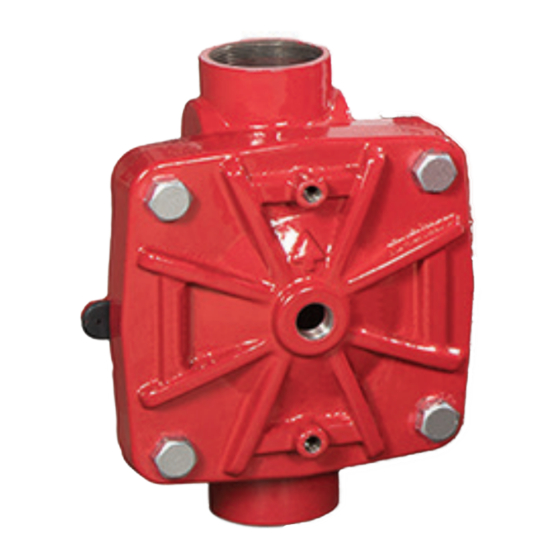
The TYCO DV-5
Automatic Water
a
Control Valves are diaphragm type
valves that can be used in single inter-
lock preaction fire protection systems.
When properly trimmed, the double
seat design of the DV-5
a
provides actuation of fire alarms upon
system operation.
The diaphragm style design of the
DV-5
Valve allows external resetting,
a
providing for easy resetting of a deluge
system without having to open a valve
handhole cover to manually reposition
a clapper and/or latch mechanism.
Simply re-pressurizing the diaphragm
chamber resets the valve.
The DV-5
features internal and exter-
a
nal coating of the valve to provide
corrosion resistance. The external cor-
rosion resistance of the epoxy coating
permits the use of the DV-5
rosive atmospheres associated with
many types of industrial processing
plants and outdoor installations.
The DV-5
Valves are offered with the
a
DV-5
Valve and separately ordered
a
semi-assembled trim shown in Figures
7, 8, and 9, or, for ease of installa-
tion, with the DV-5
Valve completely
a
trimmed with or without a System Main
Control Valve.
The DV-5
Single Interlock Preaction
a
System utilizes automatic sprinklers
and a supplemental detection system.
The supplemental detection system is
comprised of wet pilot lines, dry pilot
lines, or electric detection comprised
of heat detectors, smoke detectors,
manual pull stations, etc. Actuation
of the detection system automatically
operates (releases) the DV-5
allowing water to flow into the sprinkler
piping system and to be discharged
from any sprinklers that may subse-
quently open.
IMPORTANT
Refer to Technical Data Sheet
TFP2300 for warnings pertaining to
regulatory and health information.
Page 1 of 34
Valve also
in cor-
a
End Connection
Inlet
Thread
Groove
Flange
Flange
Typically, the system designer selects
the detection components for a single
interlock preaction system that will
respond to a fire sooner than the auto-
Valve,
a
matic sprinklers. Consequently, the
system will experience a minimal delay
in water delivery over that for a wet pipe
sprinkler system because the system
will have essentially filled with water
before a sprinkler operates. The DV-5
Valve with Single Interlock Preac-
tion Trim automatically supervises the
integrity of the overall system. Super-
vision is provided by monitoring a rel-
atively low air pressure in the system
via a low pressure alarm switch so as
SEPTEMBER 2018
Available End Connections and Weights — lb (kg)
1-1/2
2
Outlet
(40)
(50)
26
25
Thread
(11,8)
(11,3)
25
25
Groove
(11,3)
(11,3)
Groove
N/A
N/A
Flange
N/A
N/A
a
Worldwide
www.tyco-fire.com
Contacts
Nominal Valve Size
ANSI Inches
(DN)
3
4
6
(80)
(100)
(150)
N/A
N/A
N/A
60
95
177
(27,2)
(43,1)
(80,3)
66
106
190
(30,0)
(48,1)
(86,2)
72
116
204
(32,7)
(52,6)
(92,5)
to detect leaks in the system that oth-
erwise would result in unwanted water
discharge should the system operate in
a fire condition.
Supervised single interlock preac-
tion systems are generally used to
protect areas where there is danger
of serious water damage that might
result from damaged automatic sprin-
klers or piping. Typically, such areas
include computer rooms, storage
areas for valuable artifacts, libraries,
and archives.
Single interlock preaction systems are
also effectively used to protect proper-
8
(200)
N/A
327
(148,3)
346
(157,0)
365
(165,6)
TFP1425
Advertisement

Related Manuals for Johnson Controls Tyco DV-5a Series


Summary of Contents for Johnson Controls Tyco DV-5a Series
- Page 1 Worldwide www.tyco-fire.com Contacts DV-5 Automatic Water Control Valve Single Interlock Preaction Fire Protection Systems 1-1/2 Inch to 8 Inch (DN40 to DN200) General Description The TYCO DV-5 Automatic Water Control Valves are diaphragm type valves that can be used in single inter- lock preaction fire protection systems.
- Page 2 TFP1425 Page 2 of 34 Nominal Valve Size ANSI Inch (DN) Item Description Qty. 1-1/2 (DN40) 2 (DN50) 3 (DN80) 4 (DN100) 6 (DN150) 8 (DN200) Valve Body Diaphragm 545000020 545000020 545000030 545000040 545000060 545000080 Diaphragm Cover Hex Bolt, Short 545100001 545100001 545100002...
- Page 3 TFP1425 Page 3 of 34 Port Sizes, NPT Inch per ANSI B1.20.1 Port Port Description 1-1/2 (DN40) (DN50) (DN80) (DN100) (DN150) (DN200) Diaphragm Chamber Supply Water Supply Pressure & Alarm Test Alarm Actuation Automatic Drain Valve System Drain Main Drain 1-1/4 System Air Supply SYSTEM OPEN TO ATMOSPHERE...
-
Page 4: Technical Data
TFP1425 Page 4 of 34 ties where a pre-alarm of a possible fire When the system pressure is greater DIMENSIONS SHOWN condition may allow time for fire extin- than 175 psi (12,1 bar), provision is to be ARE APPLICABLE TO guishment by alternate suppression made to replace the standard order 300 ALL END CONNECTION... -
Page 5: Materials Of Construction
TFP1425 Page 5 of 34 FLOW RATE IN LITERS PER MINUTE (LPM) (1 GPM = 3,785 LPM) 1000 2000 3000 5000 7000 10000 15000 0,600 0,500 0,400 0,300 0,200 0,100 0,090 0,080 0,070 0,060 0,050 0,040 0,030 0,022 1000 2000 3000 4000 FLOW RATE IN GALLONS PER MINUTE (GPM) - Page 6 TFP1425 Page 6 of 34 SYSTEM PIPING WITH AUTOMATIC SPRINKLERS - NORMALLY DRY INSPECTOR'S TEST CONNECTION (AT MOST HYDRAULICALLY DEMANDING LOCATION OF WET PILOT LINE) REMOTE MANUAL WET PILOT SPRINKLER CONTROL DETECTION SYSTEM STATION (MINIMUM 1/2" PIPE AND DRAIN DRAIN (WHEN AUTOMATIC SPRINKLERS) SPECIFIED)
- Page 7 TFP1425 Page 7 of 34 SYSTEM PIPING WITH AUTOMATIC SPRINKLERS - NORMALLY DRY INSPECTOR'S TEST CONNECTION (AT MOST REMOTE LOCATION FROM DV-5A VALVE) REMOTE MANUAL PRESSURE DRY PILOT SPRINKLER CONTROL ALARM DETECTION SYSTEM DRY PILOT STATION SWITCH ACTUATOR (MINIMUM 1/2" PIPE AND DRAIN DRAIN (WHEN...
- Page 8 TFP1425 Page 8 of 34 SYSTEM PIPING WITH AUTOMATIC SPRINKLERS - NORMALLY DRY ELECTRIC DETECTION SYSTEM (TYPICALLY 24 VOLTS DC) HEAT DETECTORS, SMOKE DETECTORS, MANUAL PULL STATIONS, ETC. SOLENOID DELUGE VALVE VALVE RELEASING PANEL (TYPICALLY (AUTOMATIC 24 VOLTS DC) CONTROL UNIT WITH BATTERY BACK-UP) SYSTEM DRAIN VALVE...
- Page 9 TFP1425 Page 9 of 34 NOTES: The dew point of the pilot line air pressure must be maintained below the lowest ambient temperature to which the dry pilot actuation system will be exposed. Accumulation of water in the pilot line connection to the Actuator will lower the air pressure at which the actuator will open and possibly prevent proper operation.
-
Page 10: Installation
TFP1425 Page 10 of 34 Installation Step 5. The Main Drain and Drip Funnel relieve at a pressure which is in accor- Drain may be interconnected provided dance with the requirements of the a check valve is located at least 12 authority having jurisdiction. - Page 11 TFP1425 Page 11 of 34 1-1/2" (DN40) AND 2" (DN50) Assemble in order VALVES ONLY from A to L Notes: 1. Port Connections P1 through P7 are described in Figure 2. 2. External Trim Connections C1 through C5 are described in Figure 16. 3.
- Page 12 TFP1425 Page 12 of 34 1-1/2" (DN40) AND 2" (DN50) Assemble in order VALVES ONLY from A to M Notes: 1. Port Connections P1 through P7 are described in Figure 2. 2. External Trim Connections C1 through C5 are described in Figure 17. 3.
- Page 13 TFP1425 Page 13 of 34 1-1/2" (DN40) AND 2" (DN50) Assemble in order VALVES ONLY from A to L Notes: 1. Port Connections P1 through P7 are described in Figure 2. 2. External Trim Connections C1 through C5 are described in Figure 18. 3.
- Page 14 TFP1425 Page 14 of 34 26 50 Notes: 1. Port Connections P1 through P7 are described in Figure 2. 2. External Trim Connec- tions C1 through C5 are described in Figure 16. 3. When ordering pre- assembled "DV-5A Valve with Galvanized Valve Trim" or pre-assembled "DV-5A 1 21 Valve with Galvanized Valve...
- Page 15 TFP1425 Page 15 of 34 ITEM QTY. DESCRIPTION CH 1-1/2 IN. (DN40) 2 IN. (DN50) 3 IN. (DN80) 4 IN. (DN100) 6 IN. (DN150) 8 IN. (DN200) UNION 1/2" 1/2" 1/2" 1/2" 1/2" 1/2" ✓ STREET ELBOW 1/4" x 90° 1/4"...
- Page 16 TFP1425 Page 16 of 34 28 54 Notes: 1. Port Connections P1 through P7 are described in Figure 2. 2. External Trim Connec- tions C1 through C5 are described in Figure 17. 3. When ordering pre- assembled "DV-5A Valve with Galvanized Valve Trim" or pre-assembled "DV-5A Valve with Galvanized Valve 1 23...
- Page 17 TFP1425 Page 17 of 34 ITEM QTY. DESCRIPTION CH 1-1/2 IN. (DN40) 2 IN. (DN50) 3 IN. (DN80) 4 IN. (DN100) 6 IN. (DN150) 8 IN. (DN200) UNION 1/2" 1/2" 1/2" 1/2" 1/2" 1/2" ✓ STREET ELBOW 1/4" x 90° 1/4"...
- Page 18 TFP1425 Page 18 of 34 26 51 Notes: 1. Port Connections P1 through P7 are described in Figure 2. 2. External Trim Connections C1 through C5 are described in Figure 18. 3. When ordering pre-assembled "DV-5A Valve with Galvanized Valve Trim" or pre-assembled "DV-5A Valve with Galvanized 1 21 Valve Trim and Butterfly Valve",...
- Page 19 TFP1425 Page 19 of 34 ITEM DESCRIPTION CH 1-1/2 IN. (DN40) 2 IN. (DN50) 3 IN. (DN80) 4 IN. (DN100) 6 IN. (DN150) 8 IN. (DN200) PIPE PLUG 3/4” 3/4” 3/4” 3/4” 3/4” 3/4” ✓ UNION 1/2” 1/2” 1/2” 1/2” 1/2”...
- Page 20 TFP1425 Page 20 of 34 Nominal Inches Valve (mm) Size ANSI Inches (DN) 1-1/2 10.4 15.7 16.2 10.2 (40) (71) (246) (264) (399) (411) (185) (259) (203) (31) 10.4 15.7 16.2 10.2 (50) (71) (246) (264) (399) (411) (185) (259) (97) (74) 10.9...
- Page 21 TFP1425 Page 21 of 34 Nominal Inches Valve (mm) Size ANSI Inches (DN) 1-1/2 10.4 16.5 19.4 10.2 (40) (71) (246) (264) (419) (493) (185) (259) (203) (31) 10.4 16.5 19.4 10.2 (50) (71) (246) (264) (419) (493) (185) (259) (97) (74) 11.4...
- Page 22 TFP1425 Page 22 of 34 Nominal Inches Valve (mm) Size ANSI Inches (DN) 1-1/2 10.4 15.7 16.2 10.2 (40) (71) (246) (264) (399) (411) (185) (259) (203) (31) 10.4 15.7 16.2 10.2 (50) (71) (246) (264) (399) (411) (185) (259) (97) (74) 10.9...
- Page 23 TFP1425 Page 23 of 34 Valve Setting Step 12. Open the Supervisory Air NOTICE Supply Valve (R) to reestablish super- In order to prevent the possibility of a Procedure visory system air pressure at nominally subsequent operation of an overheated 10 psi (0,68 bar).
- Page 24 TFP1425 Page 24 of 34 Item Description Item Description External Trim Connections DV-5 Valve Diaphragm Gauge Diaphragm Supply Connection System Main Control Valve System Gauge Water Motor Alarm Connection Waterflow Pressure Switch Manual Control Station Wet Pilot Line Connection Main Drain Valve Manual Reset Actuator Supervisory Air Supply Connection System Drain Valve...
- Page 25 TFP1425 Page 25 of 34 Item Description Item Description External Trim Connections DV-5 Valve Manual Reset Actuator Diaphragm Supply Connection System Main Control Valve Diaphragm Supply Valve Water Motor Alarm Connection Waterflow Pressure Switch Diaphragm Supply Strainer Dry Pilot Line Connection Main Drain Valve Supervisory Air Supply Valve Dry Pilot Air Supply Connection...
- Page 26 TFP1425 Page 26 of 34 Item Description Item Description External Trim Connections DV-5 Valve System Gauge Diaphragm Supply Connection System Main Control Valve Manual Control Station Water Motor Alarm Connection Waterflow Pressure Switch Manual Reset Actuator Supervisory Air Supply Connection Main Drain Valve Diaphragm Supply Valve Waterflow Pressure Alarm Switch...
-
Page 27: Care And Maintenance
TFP1425 Page 27 of 34 Care and inadvertently trip, if its water supply Supervisory Low Pressure Switch (T) pressure is quickly restored. should return to its normal condition. Maintenance A drop in the water supply pressure Pressure Relief Valve Maintenance to below its normal range (as in the Over pressurization of the system The following procedures and inspec-... - Page 28 TFP1425 Page 28 of 34 Step 4. Verify that there is a flow of • Open System Main Control Valve (B) • Fire alarm setting at approximately one turn beyond position at which water from the Dry Pilot Actuator (U) 14.5 psi (1,0 bar) below the minimum water just begins to flow from Main drain connection.
- Page 29 TFP1425 Page 29 of 34 Step 3. Loosen and remove the union • Press the Reset Knob on the Man- between the Diaphragm Cover and the ual Reset Actuator (N) and hold it a Torque ft-lb Nominal MRA-1 Manual Reset Actuator (N) and few seconds until water stops flow- (N∙m) Valve Sizes...
- Page 30 TFP1425 Page 30 of 34 Limited AMERICAS G x G Warranty Valve Size Electric 1-1/2 in. (DN40) 551011115 551011215 551011315 For warranty terms and conditions, visit www.tyco-fire.com. 2 in. (DN50) 551011120 551011220 551011320 Ordering 3 in. (DN80) 551011130 551011230 551011330 Procedure 4 in.
- Page 31 TFP1425 Page 31 of 34 AMERICAS1 EMEA2 APAC3 G x G Electric Electric Electric Valve Size 1½ in. (DN40) 550011115 550011215 550011315 550111115 550111215 550111315 550011115 550011215 550011315 2 in. (DN50) 550011120 550011220 550011320 550111120 550111220 550111320 550011120 550011220 550011320 3 in.
- Page 32 TFP1425 Page 32 of 34 REGIONS OF TYPICAL AVAILABILITY (indicated by “✔”) AMERICAS — — — ✔ ✔ ✔ ✔ EMEA ✔ ✔ ✔ ✔ ✔ ✔ ✔ APAC ✔ ✔ ✔ ✔ ✔ ✔ ✔ Nominal Groove Valve Size G x G F X F ANSI F x G ANSI...
- Page 33 TFP1425 Page 33 of 34 CONSIDERED FOR USE WITH ACTUATION TYPE: Data ACCESSORIES, DELUGE FIRE PROTECTION SYSTEMS Sheet Wet Pilot Dry Pilot Electric Waterflow Pressure Alarm Switch, Potter PS10-2 (America/APAC) 25720 — ✔ ✔ ✔ Waterflow Pressure Alarm Switch PS10-1 (EMEA) 0260 —...
- Page 34 1400 Pennbrook Parkway, Lansdale, PA 19446 | Telephone +1-215-362-0700 © 2018 Johnson Controls. All rights reserved. All specifications and other information shown were current as of document revision date and are subject to change without notice. NATIONAL FIRE PROTECTION ASSOCIATION and NFPA are registered trademarks of National Fire Protection Association;...