
Related Manuals for Gree GUHD09NK3FO


Summary of Contents for Gree GUHD09NK3FO
- Page 1 U-MATCH SERIES DC INVERTER AIR CONDITIONERS SERVICE MANUAL T1/R410A/50Hz (GC201304 - )
-
Page 2: Table Of Contents
CONTENTS PRODUCT ....................2 1 MODELS LIST ......................2 1.1 Outdoor Unit ........................... 2 1.2 Indoor Unit ..........................3 2 NOMENCLATURE ....................4 2.1 Outdoor Unit ..........................4 2.2 Intdoor Unit..........................4 3 PRODUCT DATA ..................... 5 3.1 Product Data of Indoor Unit ....................5 3.2 Operation Range ........................ - Page 3 INSTALLATION ................... 48 1 INDOOR UNIT INSTALLATION ................48 1.1 Installation of Duct Type....................... 48 1.2 Installation of Floor Ceiling Type..................54 1.3 Installation of Cassette Type....................60 2 OUTDOOR UNIT INSTALLATION ................. 66 3 REFRIGERATION PIPING WORK ................ 68 3.1 Refrigeration Piping Work Procedures and Caution in Connecting ........
- Page 4 U-Match Series DC Inverter Service Manual PRODUCT...
-
Page 5: Product
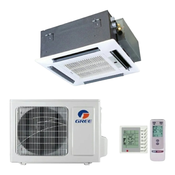
U-Match Series DC Inverter Service Manual PRODUCT 1 MODELS LIST 1.1 Outdoor Unit Power Supply Model Name Product Code Appearance (V, Ph, Hz) GUHD09NK3FO CF090W0630 220-240V~ 50Hz GUHD12NK3FO CF090W0640 220-240V~ 50Hz GUHD18NK3FO CF090W0650 220-240V~ 50Hz GUHD24NK3FO CF090W0660 220-240V~ 50Hz GUHD30NK3FO... -
Page 6: Indoor Unit
U-Match Series DC Inverter Service Manual 1.2 Indoor Unit Nominal Capacity Power Type Model Name Product Code Cooling/Heating Supply Appearance (kW) (V, Ph, Hz) GFH09K3FI CF060N0420 2.7/2.9 GFH12K3FI CF060N0430 3.5/3.8 220-240V~ 50Hz GFH18K3FI CF060N0440 5.0/5.6 GFH24K3FI CF060N0450 7.0/8.0 220-240V~ 50Hz Duct GFH30K3FI CF060N0460... -
Page 7: Nomenclature
U-Match Series DC Inverter Service Manual 2 NOMENCLATURE 2.1 Outdoor Unit Description Options Gree Electric Appliances Inc Capital Letter :G Unit Type U=U-Match Outdoor Unit C=Cool Only Product Type H=Heat Pump without Aux Electric Heaters N=Constant Frequency Compressor Power Supply... -
Page 8: Product Data
3.1 Product Data of Indoor Unit 3.1.1 Duct Type Indoor unit GFH09K3FI GFH12K3FI GFH18K3FI GFH24K3FI Product Code CF060N0420 CF060N0430 CF060N0440 CF060N0450 Model Outdoor unit GUHD09NK3FO GUHD12NK3FO GUHD18NK3FO GUHD24NK3FO Product Code CF090W0630 CF090W0640 CF090W0650 CF090W0660 Cooling Capacity 2.7(0.80-3.40) 3.5(0.90-3.70) 5.0(1.60-5.50) 7.0(2.20-8.50) - Page 9 U-Match Series DC Inverter Service Manual Indoor unit GFH30K3FI GFH36K3FI GFH36K3FI GFH42K3FI Product Code CF060N0460 CF060N0470 CF060N0470 CF060N0480 Model Outdoor unit GUHD30NK3FO GUHD36NK3FO GUHD36NM3FO GUHD42NK3FO Product Code CF090W0670 CF090W0680 CF090W0690 CF090W0700 Cooling Capacity 8.3(2.40-8.70) 10.0(3.20-11.50) 10.0(3.20-11.50) 11.5(3.60-12.50) Capacity Heating Capacity 9.2(2.40-9.90) 12.0(2.90-14.50) 12.0(2.90-14.50)
- Page 10 U-Match Series DC Inverter Service Manual Indoor unit GFH42K3FI GFH48K3FI GFH48K3FI GFH60K3FI Product Code CF060N0480 CF060N0490 CF060N0490 CF060N0500 Model Outdoor unit GUHD42NM3FO GUHD48NK3FO GUHD48NM3FO GUHD60NM3FO Product Code CF090W0710 CF090W0720 CF090W0730 CF090W0740 Cooling Capacity 11.5(3.60-12.50) 14.0(6.00-14.50) 14.0(6.00-14.50) 16.0(7.4~16.5) Capacity Heating Capacity 13.5(3.90-15.50) 15.5(5.20-17.00) 15.5(5.20-17.00)
- Page 11 U-Match Series DC Inverter Service Manual 3.1.2 Cassette Type Indoor unit GKH12K3FI GKH18K3FI GKH24K3FI Product Code ET010N0670 ET010N0680 ET010N0690 Model Outdoor unit GUHD12NK3FO GUHD18NK3FO GUHD24NK3FO Product Code CF090W0640 CF090W0650 CF090W0660 Cooling Capacity 3.5(0.90-3.90) 5.0(1.60-5.80) 7.0(2.40-8.50) Capacity Heating Capacity 3.8(0.90-4.10) 5.5(1.40-6.50) 8.0(2.40-9.50) PdesignH Cooling...
- Page 12 U-Match Series DC Inverter Service Manual Indoor unit GKH30K3FI GKH36K3FI GKH36K3FI GKH42K3FI Product Code ET010N0740 ET010N0700 ET010N0700 ET010N0710 Model Outdoor unit GUHD30NK3FO GUHD36NK3FO GUHD36NM3FO GUHD42NK3FO Product Code CF090W0670 CF090W0680 CF090W0690 CF090W0700 Cooling Capacity 8.3(2.60-9.20) 10.0(3.20-11.50) 10.0(3.20-11.50) 11.0(3.30-12.00) Capacity Heating Capacity 9.2(2.40-9.90) 12.0(2.90-14.50) 12.0(2.90-14.50)
- Page 13 U-Match Series DC Inverter Service Manual Indoor unit GKH42K3FI GKH48K3FI GKH48K3FI GKH60K3FI Product Code ET010N0710 ET010N0720 ET010N0720 ET010N0730 Model Outdoor unit GUHD42NM3FO GUHD48NK3FO GUHD48NM3FO GUHD60NM3FO Product Code CF090W0710 CF090W0720 CF090W0730 CF090W0740 Cooling Capacity 11.0(3.30-12.00) 14.0(6.00-14.80) 14.0(6.00-14.80) 16.0(7.4~16.5) Capacity Heating Capacity 12.5(3.60-15.00) 16.0(5.20-18.00) 16.0(5.20-18.00)
- Page 14 U-Match Series DC Inverter Service Manual 3.1.3 Floor-ceiling Type Indoor unit GTH09K3FI GTH12K3FI GTH18K3FI GTH24K3FI Product Code ED020N0650 ED020N0660 ED020N0670 ED020N0680 Model Outdoor unit GUHD09NK3FO GUHD12NK3FO GUHD18NK3FO GUHD24NK3FO Product Code CF090W0630 CF090W0640 CF090W0650 CF090W0660 Cooling Capacity 2.7(0.80-3.50) 3.5(0.90-3.90) 5.0(1.60-5.80) 7.0(2.40-8.20) Capacity Heating Capacity 2.9(0.80-3.80)
- Page 15 U-Match Series DC Inverter Service Manual Indoor unit GTH30K3FI GTH36K3FI GTH36K3FI GTH42K3FI Product Code ED020N0690 ED020N0700 ED020N0700 ED020N0710 Model Outdoor unit GUHD30NK3FO GUHD36NK3FO GUHD36NM3FO GUHD42NK3FO Product Code CF090W0670 CF090W0680 CF090W0690 CF090W0700 Cooling Capacity 8.5(2.60-9.20) 10.0(3.20-11.50) 10.0(3.20-11.50) 11.5(3.60-12.50) Capacity Heating Capacity 9.2(2.40-9.90) 12.0(2.90-14.50) 12.0(2.90-14.50)
- Page 16 U-Match Series DC Inverter Service Manual Indoor unit GTH42K3FI GTH48K3FI GTH48K3FI GTH60K3FI Product Code ED020N0710 ED020N0720 ED020N0720 ED020N0730 Model Outdoor unit GUHD42NM3FO GUHD48NK3FO GUHD48NM3FO GUHD60NM3FO Product Code CF090W0710 CF090W0720 CF090W0730 CF090W0740 Cooling Capacity 11.5(3.60-12.50) 14.0(6.00-14.80) 14.0(6.00-14.80) 16.0(7.4~16.5) Capacity Heating Capacity 13.5(3.90-15.50) 16.0(5.20-18.00) 16.0(5.20-18.00)
-
Page 17: Operation Range
3.3 Electrical Data 3.3.1 Outdoor unit Table 1-4-1 Electrical Data of Outdoor Unit Min. Power Compressor Fan Motor Fuse/Breaker Supply Capacity Model Power Supply Qty. Cord V/Ph/Hz GUHD09NK3FO 220-240,1,50 <1 GUHD12NK3FO 220-240,1,50 <1 GUHD18NK3FO 220-240,1,50 <1 GUHD24NK3FO 220-240,1,50 11.5 <1 GUHD30NK3FO 220-240,1,50 11.5... - Page 18 U-Match Series DC Inverter Service Manual 3.3.2 Indoor unit Table 1-4-2 Electrical Data of Indoor Unit Fuse/Breaker Min. Power Power Supply Fan Motor FLA Capacity Supply Cord Model V/Ph/Hz GFH09K3FI 220-240,1,50 <1 GFH12K3FI 220-240,1,50 <1 GFH18K3FI 220-240,1,50 <1 GFH24K3FI 220-240,1,50 <1 GFH30K3FI 220-240,1,50...
-
Page 19: Piping Diagram
U-Match Series DC Inverter Service Manual 4 PIPING DIAGRAM... - Page 20 U-Match Series DC Inverter Service Manual CONTROL...
-
Page 21: Control
U-Match Series DC Inverter Service Manual CONTROL 1 OPERATION FLOWCHART 1.1 Cooling/Dry Operation... -
Page 22: Heating Operation
U-Match Series DC Inverter Service Manual 1.2 Heating Operation... -
Page 23: Wireless Remote Controller
U-Match Series DC Inverter Service Manual 2 WIRELESS REMOTE CONTROLLER 2.1 Operation and Display View HOUR ONOFF Table 2-2-1 Operation instruction of wireless remote controller Name Function Description Signal Signal transmitter transmitter ON/OFF Press this button and the unit will be turned on; press it once more, and the unit will be turned off. When turning button off the unit, the Sleep function will be canceled, but the presetting time is still remained. - Page 24 U-Match Series DC Inverter Service Manual Press this button to set up the swing angle, which circularly changes as below: When the guide louver starts to swing up and down, if SWING functions is canceled, the air guide louver will SWING stop and remains at the current position.
-
Page 25: Wired Controller
U-Match Series DC Inverter Service Manual 3 WIRED CONTROLLER 3.1 Display View Figure 2-3-1 Appearance of wired controller Figure 2-3-2 LCD display of wired controller... - Page 26 U-Match Series DC Inverter Service Manual Table 2-3-1 Instruction to LCD Display Icons Introduction Left and right swing function Up and down swing function Air exchange function Sleep function Auto mode COOL mode DRY mode FAN mode HEAT mode Health function I-Demand function Vacation function Status display of master and slave wired controller...
-
Page 27: Operation View
U-Match Series DC Inverter Service Manual 3.2 Operation View 3.2.1 Silk Screen of Buttons Figure 2-3-3 Silk screen of buttons 3.3.2 Instruction to Function of Buttons Table 2-3-2 Instruction to buttons of wired controller Description Functions Function selection and canceling; Enter/Cancel Press it for 5s to view the ambient temperature;... - Page 28 U-Match Series DC Inverter Service Manual Notes: The following functions can be set through Function and Timer buttons: setting of ambient temperature sensor, selecting three speeds in high speed and three speeds in low speed of indoor fan motor, display setting of freeze protection error code, setting of cold air prevention and hot air hot prevention function, setting of refrigerant-lacking protection function, selecting of blowing residual heat of indoor unit, selecting of compressor electric heater mode, selecting of low-power consumption mode, selecting door control function, selecting...
-
Page 29: Operation Instruction Of Special Functions
U-Match Series DC Inverter Service Manual Figure 2-3-5 Enquiry and setting of master/slave wired controller’s address 4 OPERATION INSTRUCTION OF SPECIAL FUNCTIONS 4.1 Setting of Filter Clean Reminder Function icon will blink function. The Enter/Cancel button to cancel this function. - Page 30 U-Match Series DC Inverter Service Manual When setting the filter clean reminder function, timer zone will display 2 digits, of which the former indicates the pollution degree of operating place and the latter indicates the accumulated operating time of indoor unit. There are 4 types of situations: (1).
-
Page 31: Low Temperature Drying Function
U-Match Series DC Inverter Service Manual icon will be on. (1). If cleaning time is not reached, no mater the setting is changed or not, the accumulated operating time won’t be recalculated when pressing Enter/Cancel button; (2). If cleaning time is reached, in unit on or off state, will blink every 0.5s for reminder. -
Page 32: Enquiry Of Historical Malfunction
U-Match Series DC Inverter Service Manual Note: If the unit is not connected to outdoor ambient temperature sensor, display of outdoor ambient temperature will be shielding after energizing for 12hr. If there is malfunction of outdoor ambient temperature sensor, display of outdoor ambient temperature will be shielding after energizing for 12hr. - Page 33 U-Match Series DC Inverter Service Manual (1). Mode 1 (LCD displays 00) (2). Mode 2 (LCD displays 01) Note: Mode 1: Compressor electric heating belt starts when outdoor ambient temperature is below 35°C and stops when outdoor ambient temperature is above 37°C. When outdoor ambient temperature is within 35°C~ 37°C, the belt will keep its previous operation state.
-
Page 34: Installation Of Wired Controller
U-Match Series DC Inverter Service Manual (4). Compensate 3°C (LCD displays 03) (5). Compensate 4°C (LCD displays 04) (6). Compensate 5°C (LCD displays 05) (7). Compensate 6°C (LCD displays 06) (8). Compensate 7°C (LCD displays 07) (9). Compensate 8°C (LCD displays 08) (10). -
Page 35: Installation Of Wired Controller
U-Match Series DC Inverter Service Manual communication wire of wired controller must use shielding twisted wire. 5.3 Installation of Wired Controller Firstly, the selection and connection way of wired controller’s signal wire are as below: (1). Choose suitable signal wire: 2-core signal wire (wire diameter >=0.75mm, wire length<30m and the recommended length is 8m). - Page 36 U-Match Series DC Inverter Service Manual Malfunction of condenser temperature sensor Malfunction of outdoor ambient temperature sensor Malfunction of discharge temperature sensor Malfunction wired controller temperature sensor Wong dial switch of capacity Malfunction of outdoor main control memory chip Malfunction of electric box sensor Compressor overload protection Overload protection IPM protection...
-
Page 37: Centralized Controller
U-Match Series DC Inverter Service Manual 7 CENTRALIZED CONTROLLER 7.1 Smart Zone Controller 7.1.1 Function The smart zone controller can directly control up to 16 sets of indoor units in a control network and is available to check the running status of any unit through the LCD, including running mode, timer, fan speed, centralized control and shielding setting etc. - Page 38 U-Match Series DC Inverter Service Manual All on/off It is used to start/stop all indoor units. 7.1.4 LCD of the Controller 7.1.4.1 Outline Drawing of the LCD Figure 2-7-2 7.1.4.2 Introduction to Symbols on the LCD Figure 2-7-3 Table 2-7-2 Introduction to the Symbols on the LCD Name Description Fan speed...
-
Page 39: Additional Special Functions
7.2.1 Door control function Door control function is available for this series. In order to achieve this function, please select the door control accessories from Gree. (1). Interface instructions 1). The interface printing is DOOR-C and the type is B2B-XH-B. The wires of door control accessories must be connected to this interface;... - Page 40 U-Match Series DC Inverter Service Manual Figure 2-7-6 Illustration of door control port Table 2-7-3 Door control wiring port Terminal name Terminal instruction CN1 wiring terminal and door control interface of indoor mainboard X1(AC-L, AC-N) X1(AC-L, AC-N) wiring terminal, connected to door control input signal, rated voltage 220V. X2 wiring terminal, connected to door control input signal (2).
- Page 41 U-Match Series DC Inverter Service Manual Figure 2-7-7 Note: You can purchase the accessory from Gree. The information is as below: Name Product code Remark Controller for door control function (MK03) MC207022 One controller for one unit 7.2.2 Human sensitive function You can purchase the module of human sensitive function for this series.
- Page 42 The current consumption of module can not exceed the current capacity provided by this interface. 7.2.3 MODBUS interface The indoor unit of this series has MODBUS interface. If the user needs to connect the unit to the management system of the building, please enquire Gree for the MODBUS protocol. Figure 2-7-9 (1). Interface instruction: 1).
- Page 43 U-Match Series DC Inverter Service Manual control information to realize control and monitor of the unit. (2). Function instructions: In order to achieve this function, set the address mode and address through wired controller. Please refer to Point 3 for the setting method. You must set the address mode into long-distance control address mode. The address mode is defaulted to be connecting to centralized controller mode and the defaulted address is 1.
- Page 44 U-Match Series DC Inverter Service Manual Figure 2-7-11 Note: In order to realize the MODBUS interface function, the address mode of the unit must be set into long- distance control address mode; you can not set it into centralized control address mode, otherwise, this function can not be realized;...
- Page 45 U-Match Series DC Inverter Service Manual 1). Under off state of the unit, press Function and Timer buttons at the same time for 5s to go to the Centralized controller address mode (LCD displays 00) Long-distance control address mode (LCD displays 01) of wired controller is set to match the address of centralized controller.
- Page 46 7.2.5 Light board control: Light board interface is reserved on the mainboard of duct type unit. You can purchase Gree light board to realize control of the unit. When wired control is also connected, you can realize control of the unit through light board and wired controller.
- Page 47 U-Match Series DC Inverter Service Manual pressing any button can turn off the unit. Figure 2-7-14 7.2.6 Malfunction output of relay: There is malfunction outlet signal on the mainboard of indoor unit; when the unit occurs unrecovered malfunction, this signal will be output. (1).
- Page 48 U-Match Series DC Inverter Service Manual (3). Setting method: Do not need to set this function Notes: The interface voltage should be 220V AC intense current; If malfunction light is connected, please make sure its power is not too big (it should be within 10W), otherwise, the relay on mainboard will be burnt.
- Page 49 U-Match Series DC Inverter Service Manual 7.2.7 Reserved fresh air valve interface for duct type unit For the reserved connection way of air valve performer, connect it to F,C,O of wiring board according to the wiring diagram. Connect the public port of air valve to F, connect CLOSE to C and connect OPEN to O. Figure 2-7-17 7.2.8 Interface of anion generator For the cold plasma anion generator, connect the red line to HEALTH(X4) and the blue line to N2(X6)
- Page 50 U-Match Series DC Inverter Service Manual INSTALLATION...
-
Page 51: Installation
U-Match Series DC Inverter Service Manual INSTALLATION 1 INDOOR UNIT INSTALLATION 1.1 Installation of Duct Type 1.1.1 Before Installation After receiving the machine, please check for any transport damage. If finding any surface or internal damage, please immediately report to the transport company or equipment company in writing. After receiving the machine, please check the unit and accessories in reference to the packing list. - Page 52 U-Match Series DC Inverter Service Manual Precautions for unfavorable installation: The preparation of all pipes (connecting pipes and drainage pipes) and cables (connecting lines of wire controller, indoor unit and outdoor unit) must be ready before the installation, so as to achieve smooth installation.
- Page 53 U-Match Series DC Inverter Service Manual Gas Pipe Liquid Pipe Air Intake Drainage Pipe Electric Box Item Model 1239 1177 Name & Shape Notes Installation and Operating Instructions Insulation materials for gas pipe Insulation materials for liquid pipe Insulation materials for drainage pipe Nut M8 with gasket 4 sets, used for ceiling mounting of the indoor unit Nut and spring gasket...
- Page 54 U-Match Series DC Inverter Service Manual Installation of Drainage Pipeline: Install the drain hose in accordance with the instructions in this installation manual and keep the area warm enough to prevent condensation. Problems with the piping may lead to water leaks. (1).
- Page 55 U-Match Series DC Inverter Service Manual There is a drain port on both the left and right sides. Select (7). (8). (9). defaulted to be the one on the left side (electric box side), the port on right side has been plugged. (11).
- Page 56 U-Match Series DC Inverter Service Manual 1.1.7 Installation of air duct Supply Air Outlet Item Model 1.1.8 Installation of the Supply Air Duct (1). Name Name Hanger Filter Main Air Air Intake Pipe Supply Pipe Canvas Air Pipe Air Supply Outlet Air Intake...
-
Page 57: Installation Of Floor Ceiling Type
U-Match Series DC Inverter Service Manual The maximum length of the duct means the maximum length of the supply air duct plus the maximum length of the return air duct. kept open (2). (3). plate. (4). Connect one end of the return air duct to the return air outlet of the unit by rivets and the other to the return air louver. - Page 58 U-Match Series DC Inverter Service Manual building, make sure that the electrical insulation must comply with applicable standards. 1.2.2 Installation Site (1). Install the unit at a place where is strong enough to withstand the weight of the unit. (2). the room.
- Page 59 U-Match Series DC Inverter Service Manual Screwing the screw (4). down. Screwing the screw Put the hanger bolt into the clasp of the indoor unit and tighten screws on the hanger to prevent the indoor unit from moving. Floor type Left side panel...
- Page 60 U-Match Series DC Inverter Service Manual Ceiling type Ceiling Suspension bolt Spring washer Left side panel panel Hanger (7). Adjust the height of the unit to make the drain pipe slant slightly downward so that the drainage will become much smoother. 1.2.4 Leveling The water level test must be done after installing the indoor unit to make the unit is horizontal, as shown below.
- Page 61 U-Match Series DC Inverter Service Manual Model (1). not remain trapped inside the pipe. (2). (3). Install the drain piping as shown and take measures against condensation. Improperly rigged piping could lead to leaks and eventually wet furniture and belongings. Indoor unit drain hose Extension drain piping...
- Page 62 U-Match Series DC Inverter Service Manual (1). For determining the position of the drain hose, perform the following procedures. (2). Insert the drain pipe to the drain outlet of the unit and then tighten the clamp securely with tape. (Figure (3).
-
Page 63: Installation Of Cassette Type
U-Match Series DC Inverter Service Manual 1.3 Installation of Cassette Type 1.3.1 Before Installation After receiving the machine, please check for any transport damage. If finding any surface or internal damage, please immediately report to the transport company or equipment company in writing. After receiving the machine, please check the unit and accessories in reference to the packing list. - Page 64 U-Match Series DC Inverter Service Manual (1). nstall the hoisting stand on the hoisting screw by using nuts and gaskets at both the upper and lower sides of the hoisting stand. To prevent the gasket from breaking off, a gasket anchor board can be helpful. (2).
- Page 65 U-Match Series DC Inverter Service Manual (1). The connecting pipe should be located corresponding to the marking. (2). (3). Latch other two hooks. (4). Tighten the screws until the thickness of the sealing material between the panel and the indoor unit (7).
- Page 66 U-Match Series DC Inverter Service Manual (8). If gap still exists between ceiling and decoration panel after tightening the screws, readjust the height of (9). 1.3.7 Dimension Data...
- Page 67 U-Match Series DC Inverter Service Manual Item Model 1.3.8 Installation of Drain Piping (1). not remain trapped inside the pipe. (2). (3). Install the drain piping as shown and take measures against condensation. Improperly rigged piping could lead to leaks and eventually wet furniture and belongings. Indoor unit drain hose Extension drain piping...
- Page 68 U-Match Series DC Inverter Service Manual (4). Install one water trap for each unit. (7). Installation of water trap shall consider easy cleaning in the future. (8). Connection of drainage branch pipe to the standpipe or horizontal pipe of drainage main pipe (9).
-
Page 69: Outdoor Unit Installation
U-Match Series DC Inverter Service Manual (2). (3). (4). × (wrong) withstand additional force. Drain hose(attachment) 1.3.11 Testing of Drain Piping Drain hose Test hole cover Drain vent for repair use (plastic stopper is included) (drain the water in waterspoit by this outlet vent) Test hole <Immiting water from the rest hole>... - Page 70 U-Match Series DC Inverter Service Manual building, make sure that the electrical insulation must comply with applicable standards. 2.2 Installation Site If possible, do not install the unit where it will be exposed to direct sunlight. (If necessary, install a blind (1).
-
Page 71: Refrigeration Piping Work
U-Match Series DC Inverter Service Manual 2.4 Dimension Data Item Model 1349 3 REFRIGERATION PIPING WORK 3.1 Refrigeration Piping Work Procedures and Caution in Connecting 3.1.1 Flare Processing (1). Cut the connection pipe with the pipe cutter and remove the burrs. (2). - Page 72 U-Match Series DC Inverter Service Manual 3.1.2 Bending Pipes (1). The pipes are shaped by your hands. Be careful not to collapse them. (2). Pipe (3). Heat insulating pipe or stretch the pipes more than three times. (4). Cutter collapsed. In this case, cut the heat insulating pipe with a sharp cutter Cutt line bending the pipe as you want, be sure to put the heat insulating pipe back on the pipe, and secure it with tape.
- Page 73 U-Match Series DC Inverter Service Manual Pipe Diameter Tightening Torque Be sure to connect the gas pipe after connecting the liquid pipe completely. The tightening method is the same as that as at the indoor side. For both indoor and outdoor unit side, check the joints for gas leaking by the use of a gas leakage detector without fail when the pipes are connected.
- Page 74 U-Match Series DC Inverter Service Manual 3.1.7 Vacuum and Gas Leakage Inspection 3.1.7.1 Vacuum (1). (2). Connect the hose at the low pressure side of the manifold valve assembly to the service port of the unit’s gas valve, and meanwhile the gas and liquid valves should be kept closed in case of refrigerant leak. (3).
-
Page 75: Electric Wiring Work
U-Match Series DC Inverter Service Manual Outdoor Oil bend Indoor Oil bend Max. Height Difference Item Size of Fitting Pipe(Inch) Drainage pipe(Outer Max. Pipe Length between Diameter × wall thickness) (mm) Liquid Model 4 ELECTRIC WIRING WORK 4.1 Wiring Precautions Before obtaining access to terminals, all supply circuits must be disconnected. -
Page 76: Electrical Wiring
U-Match Series DC Inverter Service Manual The power source capacity must be the sum of the air conditioner current and the current of other capacity. voltage. 4.2 Electrical Wiring (1). 4). Shape the loop wire properly, place it on the terminal board and tighten securely with the terminal screw using a screwdriver. - Page 77 U-Match Series DC Inverter Service Manual (4). Electric wiring between the indoor and outdoor units...
- Page 78 U-Match Series DC Inverter Service Manual Electric wiring of indoor unit side The F, C, O connect to the COMMOM, CLOSE and OPEN terminal of the fresh air valve respectively. Power supply terminal board Electric Communication Seal here box cover terminal board to avoid leakage...
- Page 79 U-Match Series DC Inverter Service Manual interference. covers. Do not bundle the connection wire of the wired controller and the communication cord together, or arrange them in parallel, otherwise improper operation would occur. the former and small clamps for the latter. If the indoor unit connection cord (to the outdoor unit) and power supply are wired incorrectly, the air conditioner may be damaged.
- Page 80 U-Match Series DC Inverter Service Manual...
- Page 81 U-Match Series DC Inverter Service Manual MAINTENANCE...
-
Page 82: Maintenance
U-Match Series DC Inverter Service Manual MAINTENANCE 1 TROUBLE TABLE 1.1 Main Control Malfunction Table 4-1-1 Fault Display on Indoor Wired Controller Origin of Error code Malfunction name malfunction Control description signal When outdoor unit detects the high pressure switch is cut off for 3s successively, high pressure protection will occur. - Page 83 U-Match Series DC Inverter Service Manual If the outdoor condenser temperature sensor is detected of open circuit or short circuit for 5s successively, condenser temperature Malfunction Condenser sensor malfunction will be reported. The unit can automatically of condenser temperature resume operation after the malfunction disappears. If condenser temperature sensor sensor temperature sensor malfunction occurs in fan mode, only the...
-
Page 84: Description Of Drive Malfunction
U-Match Series DC Inverter Service Manual 1.2 Description of Drive Malfunction Main board dual 8 numeral tube Display Codes for Outdoor Unit of 09~48k Outdoor unit display of Malfunction Item Indoor Unit Display dual 8 numeral tube DC busbar over-voltage protection IPM or PFC over-temperature protection Current sense circuit error IPM or PFC temperature sensor error... -
Page 85: Flow Chart Of Troubleshooting
U-Match Series DC Inverter Service Manual 2 FLOW CHART OF TROUBLESHOOTING 2.1 Troubleshooting Flow Chart of Main Control Malfunction E1 High Pressure Protection protection Reconnect wire according to the circuit diagram Check if the system high Check if the wiring Check if the high Replace the high pressure is... - Page 86 U-Match Series DC Inverter Service Manual E2 Freeze Protection Freeze protection is normal protection but not abnormal malfunction. If freeze protection occurs frequently and air outlet. E3 stands for three statuses: (1). Low pressure protection (48K\60K); (2). Refrigerant lacking protection; (3).
- Page 87 U-Match Series DC Inverter Service Manual E4 Discharge Protection E4 protection Replace the discharge temperature sensor Check if the discharge Check if the temperature around discharge Replace the outdoor compressor discharge temperature sensor main control board temperature sensor is normal exceeds 115 Check if there is leakage in the system pipeline;...
- Page 88 U-Match Series DC Inverter Service Manual E9 Full Water Protection E9 protection Short circuit the full water If the unit is protection interface on indoor installed with mainboard according to the circuit water pump diagram Check if the water pump Replace the water pump works normally Replace the full water switch...
- Page 89 U-Match Series DC Inverter Service Manual F1 Malfunction of Evaporator Temperature Sensor Malfunction of evaporator temperature sensor Check if the evaporator Correctly insert the temperature sensor on temperature mainboard is inserted on the sensor on the needle stand correctly needle stand Disconnect Replace the the temperature sensor and...
- Page 90 U-Match Series DC Inverter Service Manual F3 Malfunction of Outdoor Ambient Temperature Sensor Malfunction of outdoor ambient temperature sensor Check Correctly insert the if the outdoor ambient temperature sensor on temperature sensor on mainboard the needle stand is inserted on the needle stand correctly Disconnect Replace the...
- Page 91 U-Match Series DC Inverter Service Manual F5 Malfunction of Wired Controller Temperature Sensor Malfunction of wired controller temperature sensor Replace the wired controller H6 Malfunction of Outdoor Fan Motor Malfunction of discharge temperature sensor Check if the Correctly connect the control wire of outdoor fan motor is control wire of fan motor connected on the outdoor...
-
Page 92: Troubleshooting Flow Chart Of Drive Malfunction
2.2 Troubleshooting Flow Chart of Drive Malfunction Note: For Outdoor Unit Drive (Inverter) by Single-phase Motor (Applicable to GUHD09NK3FO/GUHD12NK3FO/GUHD18NK3FO/GUHD24NK3FO/ GUHD30NK3FO/ GUHD36NK3FO/ GUHD42NK3FO/ GUHD48NK3FO) P0 Drive module reset P7 IPM or PFC temperature sensor error PA AC current protection (input side) - Page 93 U-Match Series DC Inverter Service Manual P8 IPM or PFC over-temperature protection P8 is displayed on the wired controller P8 is displayed in the mainboard 88 Indicating lamp Is the IPM or PFC module of mainboard tightened Replace the Tighten the IPM mainboard or PFC module Work normally...
- Page 94 U-Match Series DC Inverter Service Manual P6 Drive-to-main-control communication error Lc Compressor Startup Failure Lc is displayed on the wired controller Lc is displayed in the mainboard 88 indicating lamp Replace the mainboard. Does it work normally? Replace the compressor Work normally...
- Page 95 U-Match Series DC Inverter Service Manual P5 Compressor current protection H7 Compressor motor desynchronizing H5 IPM protection Ld Phase loss P5, H7, H5 or Ld is displayed on the wired controller P5, H7, H5 or Ld is displayed in the mainboard 88 indicating lamp adjust the Is the compressor...
- Page 96 U-Match Series DC Inverter Service Manual PU Charging circuit error PU is displayed on the wired controller PU is displayed in the mainboard 88 indicating lamp Is the PFC wire tightened or is the sequence right? Tighten the PFC Replace the wire or adjust the mainboard sequence...
- Page 97 U-Match Series DC Inverter Service Manual H6 DC fan error H6 is displayed on the wired controller H6 is displayed in the mainboard 88 indicating lamp Is the motor phase Adjust the motor sequence right? phase sequence Is the Fan wire terminal Tighten the fan loose wiring terminal...
-
Page 98: Interface
U-Match Series DC Inverter Service Manual 2.3 Interface (1). GUHD09NK3FO/GUHD12NK3FO Mainboard 40 39 SILK-SCREEN INTERFACE INSTRUCTION SILK-SCREEN INTERFACE INSTRUCTION LX_2 PFC reactor wire (yellow) LX_1 PFC reactor wire (white) Compressor Phase W Compressor Phase V Compressor Phase U DC-BUS (Reserved) - Page 99 U-Match Series DC Inverter Service Manual (2). G U H D 1 8 N K 3 F O / G U H D 2 4 N K 3 F O / G U H D 3 0 N K 3 F O / G U H D 3 6 N K 3 F O / G U H D 4 2 N K 3 F O / GUHD48NK3FO/ GUHD36NM3FO/GUHD42NM3FO/GUHD48NM3FO/GUHD60NM3FO Main Control Board SILK-SCREEN...
- Page 100 U-Match Series DC Inverter Service Manual Communication needle stand of main control drive 1-pin: +3.3V, COMM1 HEAT Compressor electric heating belt 2-pin: TXD 3-pin: RXD, 4-pin: GND Communication needle stand with indoor unit 1-pin: GND, VA-1 Chassis electric heating belt 2-pin: B, 3-pin: A Communication interface...
- Page 101 U-Match Series DC Inverter Service Manual 2). Filtering Board Printing Interface Printing Interface Neutral wire output 1 N-OUT1 N-OUT Neutral wire output (white) (white) (only for 18K) L-OUT Live wire output (red) Grounding wire (Reserved) AC-L Live wire input (red) AC-N Neutral wire input (white) (4).
-
Page 102: Ipm, Pfc Testing Method
U-Match Series DC Inverter Service Manual 2). Filtering Board: Printing Interface Printing Interface N-OUT Neutral wire output (white) L-OUT Live wire output (red) DC bus interface (connect DC-BUS AC-L Live wire input (red) to drive board) Neutral wire input (white) (Reserved) Grounding wire (screw hole) 2.4 IPM, PFC Testing Method... - Page 103 (3). If the measured voltages between L1-2P ,L2-1 P, N L1-2 , NL2-1 are all among 0.3V-0.7V, then it indicates the PFC module is normal; If any measured valve is 0, it indicates the PFC is damaged. GUHD09NK3FO/GUHD12NK3FO GUHD18NK3FO/GUHD24NK3FO/ GUHD30NK3FO/GUHD36NK3FO/ GUHD42NK3FO/...
-
Page 104: Wiring Diadram
U-Match Series DC Inverter Service Manual GUHD48NK3FO 3 WIRING DIADRAM 3.1 Outdoor unit The actual wiring should always refer to the wiring diagram of the unit. Model: GUHD09NK3FO, GUHD12NK3FO... - Page 105 U-Match Series DC Inverter Service Manual Model: GUHD18NK3FO Model: GUHD24NK3FO, GUHD30NK3FO...
- Page 106 U-Match Series DC Inverter Service Manual Model: GUHD36NK3FO Model: GUHD42NK3FO...
-
Page 107: Indoor Unit
U-Match Series DC Inverter Service Manual Model: GUHD48NK3FO 3.2 Indoor unit The actual wiring should always refer to the wiring diagram of the unit. 3.2.1 Duct Type Model: GFH09K3FI, GFH12K3FI, GFH18K3FI, GFH24K3FI, GFH30K3FI, GFH36K3FI, GFH42K3FI... -
Page 108: Indoor Unit
U-Match Series DC Inverter Service Manual Model: GFH48K3FI INDOOR UNIT COOL PLASMA GENERATOR YEGN POWER AC-N(X500) AC-L(X501) HEALTH(X4) N2(X6) N2(X6) YEGN V-NEW-CLOSE (X2) V-NEW-OPEN(X1) CN451 COM6 Close FreshA ir Valve Commom Open COM7 PUMP-C E500 OUTDOOR UNIT YEGN XT1-L XT1-N WIRE CONTROL MOTOR... - Page 109 U-Match Series DC Inverter Service Manual 3.2.3 Cassette Type Model: GKH12K3FI, GKH18K3FI Model: GKH24K3FI, GKH30K3FI...
- Page 110 U-Match Series DC Inverter Service Manual Model: GKH36K3FI, GKH42K3FI Model: GKH48K3FI...
-
Page 111: Disassembly And Assembly Procedure Of Main Parts
U-Match Series DC Inverter Service Manual 4 DISASSEMBLY AND ASSEMBLY PROCEDURE OF MAIN PARTS 4.1 Outdoor Unit 09/12K Disassembly and Assembly of external casing Remark : Step Illustration Handling Instruction 1. Remove the top cover and handle; 1. Remove external casing 2. - Page 112 U-Match Series DC Inverter Service Manual 18K: Remark : Before disassembly and assembly, make sure that the unit has been cut off from the power supply. Step Illustration Handling Instruction 1. Remove the top cover and handle; 1. Remove external casing 2.
- Page 113 U-Match Series DC Inverter Service Manual 24/30k: Remark : Before disassembly and assembly, make sure that the unit has been cut off from the power supply. Step Illustration Handling Instruction 1. Remove the top cover and handle; 1. Remove external casing 2.
- Page 114 U-Match Series DC Inverter Service Manual Remark : Before disassembly and assembly, make sure that the unit has been cut off from the power supply. Step Illustration Handling Instruction 1. Remove the top cover and handle; 1. Remove external casing 2.
- Page 115 U-Match Series DC Inverter Service Manual 42/48/60: Remark : Before disassembly and assembly, make sure that the unit has been cut off from the power supply. Step Illustration Handling Instruction 1. Remove the top cover and handle; 1. Remove external casing 2.
-
Page 116: Indoor Unit
U-Match Series DC Inverter Service Manual 4.2 Indoor Unit 4.2.1 Duct type Removal and Assembly of Fan Motor Step Illustration Handling Instruction Cut off the power supply of indoor unit. Use 1. Unplug the motor cables screwdriver to remove the electric box cover and unplug the motor cables in electric box. - Page 117 U-Match Series DC Inverter Service Manual Remark: Make sure that the power supply is cut off before disassembling and protect all the parts Step Illustration Handling Instruction guide slot sponge, and remove according to the direction screen for return air Disassembly of electrical parts box cover panel and electrical parts box Remark: Make sure that the power supply is cut off before disassembling and protect all the parts during disassembly, especially the electrical components.
- Page 118 U-Match Series DC Inverter Service Manual Disassembly of fan and motor Remark: Make sure that the power supply is cut off before disassembling and protect all the parts during disassembly. Step Illustration Handling Instruction (As is shown in Graph 10, circle represents 6 screws.) Disassembly of fan motor Disassemble the fastening screws on the fan and motor.
- Page 119 U-Match Series DC Inverter Service Manual 4.2.2 Cassette-type Unit Removal and Assembly of Fan Motor Step Illustration Handling Instruction 1. Loosen the screws 2. Remove the water tray Remove the water tray 3. Loosen the bolts 4. Remove the fan Remove the fan 5.
- Page 120 U-Match Series DC Inverter Service Manual 6. Remove the motor Remove the motor and replace it and replace it 7. Tighten the screws 8. Mount the fan and Mount the fan and use spanner to 9. Mount the water tray and tighten the screws Removal and Installation of Drainage Pump Step...
- Page 121 U-Match Series DC Inverter Service Manual 2. Remove the water tray Remove the water pump and replace it. 3. Pull out the water outlet Pull out the water outlet pipe and use screwdriver pipe and loosen the screws 4. Take out the pump Take out the pump and replace it and replace it 5.
- Page 122 U-Match Series DC Inverter Service Manual 4.2.3 Floor Ceiling Type Model: GTH30K3FI~GTH42K3FI Disassembly of panel grating module Remark: Make sure that the power supply is cut off before disassembling and protect all the parts Step Illustration Handling Instruction 1. Unscrew the 2 clasps of the upper grill Disassembly of sub- and the 2 screws of the clasps.
- Page 123 U-Match Series DC Inverter Service Manual Disassemble of water-containing plate modules Remark: Make sure the power supply is cut off before disassembling and protect all the parts during disassembly. Step Illustration Handling Instruction Disassemble of water- Remove the water-containing plate modules. containing plate modules Disassembly of evaporator components Remark: Make sure that the power supply is cut off and protect the copper tube and aluminum...
- Page 124 U-Match Series DC Inverter Service Manual 3. Disassembly of Unscrew the 3 screws and 2 nuts of support to remove the mounting support. Loosen the 2 screws of the motor attaching clamp, 4. Disassembly of motor remove the motor attaching clamp and motor attaching clamp subassembly to remove the motor.
- Page 125 U-Match Series DC Inverter Service Manual Disassembly of panel parts Remark: Make sure the power supply is cut off before disassembling and protect all the parts during disassembly. Do not scratch the outer parts. Step Illustration Handling Instruction Unscrew the 3 sides’ screws on the Disassembly of panel parts cover to remove the cover.
- Page 126 U-Match Series DC Inverter Service Manual Remark: Make sure that the power supply is cut off before disassembling and protect all the parts during disassembly. Step Illustration Handling Instruction Remove the display board, mounting support plate sub-assy for air and mounting plate of swing motor in turn. sweeping fans Disassembly of fan and motor components Remark: Make sure that the power supply is cut off before disassembling and protect all...
-
Page 127: Exploded Views And Spare Part List
U-Match Series DC Inverter Service Manual 5 EXPLODED VIEWS AND SPARE PART LIST 5.1 Outdoor Unit Model: GUHD09NK3FO/GUHD12NK3FO Exploded Views and spare parts list:... - Page 128 U-Match Series DC Inverter Service Manual GUHD09NK3FO GUHD12NK3FO Name of Part Product Code CF090W0630 Product Code CF090W0640 Part Code Quantity Part Code Quantity Front Grill 22413433 '22413433 Front Panel 0153303204P '0153303204P Axial Flow Fan '10333012 '10333012 Brushless DC Motor 15709400007...
- Page 129 U-Match Series DC Inverter Service Manual Model: GUHD18NK3FO Exploded Views and spare parts list:...
- Page 130 U-Match Series DC Inverter Service Manual GUHD18NK3FO Name of Part Product Code CF090W0650 Part Code Quantity Front Grill '22415002 Front Panel 01535013 Axial Flow Fan '10335008 Fan Motor 1570280204 Chassis Sub-assy 01195200015P Drainage Connecter '06123401 Electrical Heater '7651300403 Motor Support Assy 01805200173 Compressor Overload Protector(External) '00180030...
- Page 131 U-Match Series DC Inverter Service Manual Model: GUHD24NK3FO/ GUHD30NK3FO Exploded Views and spare parts list:...
- Page 132 U-Match Series DC Inverter Service Manual GUHD24NK3FO GUHD30NK3FO Name of Part Product Code CF090W0660 Product Code CF090W0670 Part Code Quantity Part Code Quantity Front Grill '22415003 '22415003 Cabinet '01435004P '01435004P Axial Flow Fan 10335014 '10335014 Front Side Plate '01305086P '01305086P Fan Motor '15702802 '15702802...
- Page 133 U-Match Series DC Inverter Service Manual Model: GUHD36NK3FO Exploded Views and spare parts list:...
- Page 134 U-Match Series DC Inverter Service Manual GUHD36NK3FO Name of Part Product Code CF090W0680 Part Code Quantity Front Grill '22415005 Handle '26235253 Cabinet '01435007P Front Side Plate Sub-Assy '01305508 Chassis Sub-Assy '01195315P Drainage Joint '26113009 Electrical Heater(Compressor) '7651873209 Clapboard Sub-Assy '01245253 Compressor Gasket '76713066 Compressor...
- Page 135 U-Match Series DC Inverter Service Manual Model: GUHD42NK3FO Exploded Views and spare parts list:...
- Page 136 U-Match Series DC Inverter Service Manual GUHD42NK3FO Name of Part Product Code CF090W0700 Part Code Quantity Front Grill '01575200001 Diversion Circle '10474100001 Cabinet '01514100002P Handle '26235253 Front Side Plate '01314100021P Axial Flow Fan '10434100003 Fan Motor '15704115 Motor Support Sub-Assy '01805200185 Compressor Gasket '76713066...
- Page 137 U-Match Series DC Inverter Service Manual Model: GUHD48NK3FO Exploded Views and spare parts list:...
- Page 138 U-Match Series DC Inverter Service Manual GUHD48NK3FO Name of Part Product Code CF090W0720 Part Code Quantity Front Grill '01575200001 Diversion Circle '10474100001 Cabinet '01514100002P Handle '26235253 Front Side Plate '01314100021P Axial Flow Fan '10434100003 Fan Motor '15704115 Motor Support Sub-Assy '01805200202 Chassis Sub-assy '01195200020P...
-
Page 139: Indoor Unit
U-Match Series DC Inverter Service Manual 5.2 Indoor Unit 5.2.1 Duct Type Model: GFH09K3FI exploded view and spare parts list GFH09K3FI Name of Part Product Code CF060N0420 Part Code Quantity Top Cover Board Assy '01264176 Electric Box Cover '01425200050 Left Side Plate Assy '01315200072 Electric Box Assy '01395200239... - Page 140 U-Match Series DC Inverter Service Manual Propeller Housing '22202029 Right Side Plate Assy '01314175 Hook '02112446 Centrifugal fan '10319051 Front Volute Casing '22202030 side plate sub- assy of return air frame '02225234 Filter '11725202 Temperature Sensor '390001921G Ambient Temperature Sensor '3900012123 Display Board '30294000007...
- Page 141 U-Match Series DC Inverter Service Manual Model: GFH12K3FI/GFH18K3FI exploded view and spare parts list...
- Page 142 U-Match Series DC Inverter Service Manual GFH12K3FI GFH18K3FI Name of Part Product Code CF060N0430 Product Code CF060N0440 Part Code Quantity Part Code Quantity Bottom Cover Plate '01265409 '01265409 Cover Of Air-In '01258650 '01258650 Propeller Housing '22202029 '22202029 Centrifugal fan '10319051 '10319051 Left Side Plate Sub-Assy '01315200062...
- Page 143 U-Match Series DC Inverter Service Manual Model: GFH24K3FI/GFH30K3FI exploded view and spare parts list...
- Page 144 U-Match Series DC Inverter Service Manual GFH24K3FI GFH30K3FI Name of Part Product Code CF060N0450 Product Code CF060N0460 Part Code Quantity Part Code Quantity Blower '15012454 '15012454 Blower Mounting Plate Sub-Assy ` 01325200039 '01325200039 Supporter '01805200164 '01805200164 Supporter ` 01804100140 '01804100140 Brushless DC Motor '15705200006 '15705200006...
- Page 145 U-Match Series DC Inverter Service Manual Model: GFH36K3FI/GFH42K3FI exploded view and spare parts list...
- Page 146 U-Match Series DC Inverter Service Manual GFH36K3FI GFH42K3FI Name of Part Product Code CF060N0470 Product Code CF060N0480 Part Code Quantity Part Code Quantity Main Board '30224000030 '30224000030 Terminal Board '42010194 '42010194 Terminal Board '4201025301 '4201025301 Hook '02112466 '02112466 Top Cover Board Assy '01265200086 '01265200086 Electric Box Assy...
- Page 147 U-Match Series DC Inverter Service Manual Model: GFH48K3FI exploded view and spare parts list...
- Page 148 U-Match Series DC Inverter Service Manual GFH36K3FI Name of Part Product Code CF060N0490 Part Code Quantity Display Board '30294000007 Temperature Sensor ` 3900012128 Tube Sensor ` 3900012123 Left Side Plate Sub-Assy '01315200064 Propeller Housing(Upper) '26905200010 Front Side Plate '01315200080 Centrifugal Fan '10425200002 Brushless DC Motor '15709400008...
- Page 149 U-Match Series DC Inverter Service Manual 5.2.2 Cassette Type Model: GKH12K3FI/GKH18K3FI exploded view and spare parts list.
- Page 150 U-Match Series DC Inverter Service Manual GKH18K3FI GKH12K3FI Name of Part Product Code ET010N0680 Product Code ET010N0670 Part Code Quantity Part Code Quantity Rear Grill '26909400007 '26909400007 Brushless DC Motor '15709400004 '15709400004 Water Tray Assy '01289400004 '01289400004 Water Pump '43138000024 '43138000024 Supporter '01809400005...
- Page 151 U-Match Series DC Inverter Service Manual Model: GKH24K3FI/GKH30K3FI/GKH36K3FI/GKH42K3FI exploded view and spare parts list.
- Page 152 U-Match Series DC Inverter Service Manual GKH24K3FI GKH30K3FI Name of Part Product Code ET010N0690 Product Code ET010N0740 Part Code Quantity Part Code Quantity Electric Box Cover Sub-Assy1 '20122054 '20122054 Electric Box Assy '01399400057 '01399400057 Terminal Board '4201025801 '4201025801 Terminal Board '4201025301 '4201025301 Electric Base Plate...
- Page 153 U-Match Series DC Inverter Service Manual GKH36K3FI GKH42K3FI Name of Part Product Code ET010N0700 Product Code ET010N0710 Part Code Quantity Part Code Quantity Electric Box Cover Sub-Assy1 '20122054 '20122054 Electric Box Assy '01399400057 '01399400057 Terminal Board '4201025301 '4201025301 Terminal Board '4201025301 '4201025301 Electric Base Plate...
- Page 154 U-Match Series DC Inverter Service Manual Model: GKH48K3FI/GKH60K3FI exploded view and spare parts list.
- Page 155 U-Match Series DC Inverter Service Manual GKH48K3FI Name of Part Product Code ET010N0720 Part Code Quantity Electric Box Cover Plate '01429423P Electric Box Assy '01399400074 Terminal Board '4201025801 Terminal Board '4201025301 Main Board '30224000028 Drain Pan Assy '01289400002 Centrifugal Fan '10429401 Evaporator Assy '01029400054...
- Page 156 U-Match Series DC Inverter Service Manual 5.2.3 Floor Ceiling Type Model: GTH09K3FI/GTH12K3FI/GTH18K3FI/GTH24K3FI exploded view and spare parts list.
- Page 157 U-Match Series DC Inverter Service Manual GTH09K3FI GTH12K3FI Name of Part Product Code ED020N0650 Product Code ED020N0660 Part Code Quantity Part Code Quantity Tube Sensor '390001923 '390001923 Room Sensor '39000191 '39000191 Connection Board '02229406 '02229406 Right Cover Plate '26909444 '26909444 Plate Board of Water Releasing Flume '26909442 '26909442...
- Page 158 U-Match Series DC Inverter Service Manual GTH18K3FI GTH24K3FI Name of Part Product Code ED020N0670 Product Code ED020N0680 Part Code Quantity Part Code Quantity Tube Sensor '390001923 '390001923 Room Sensor '39000191 '39000191 Connection Board '02229406 '02229406 Right Cover Plate '26909444 '26909444 Plate Board of Water Releasing Flume '26909442 '26909442...
- Page 159 U-Match Series DC Inverter Service Manual Model: GTH30K3FI/GTH36K3FI/GTH42K3FI exploded view and spare parts list.
- Page 160 U-Match Series DC Inverter Service Manual GTH30K3FI GTH36K3FI Name of Part Product Code ED020N0690 Product Code ED020N0700 Part Code Quantity Part Code Quantity Drain Pipe Sub-Assy '05235434 '05235434 Tube Sensor '390001923 '390001923 Room Sensor '39000191 '39000191 Swing Lever '10582008 '10582008 Air Louver '26909418 '26909418...
- Page 161 U-Match Series DC Inverter Service Manual GTH42K3FI Name of Part Product Code ED020N0710 Part Code Quantity Drain Pipe Sub-Assy '05235434 Tube Sensor '390001923 Room Sensor '39000191 Swing Lever '10582008 Air Louver '26909418 Swing Lever '10582009 Right Cover Plate '26909422 Installation Supporting Frame '01809402 Connection Board '02229406...
- Page 162 U-Match Series DC Inverter Service Manual Model: GTH48K3FI/GTH60K3FI exploded view and spare parts list.
- Page 163 U-Match Series DC Inverter Service Manual GTH48K3FI Name of Part Product Code ED020N0720 Part Code Quantity Water Tray Assy '01289401 Tube Sensor '3900020720G Room Sensor '39000191 Remote Controller '305100413W Air Louver '26909418 Right Cover Plate '26909422 Right Side Plate Sub-Assy '01319408 Connection Board '02229406...
- Page 164 JF00301816...