
Related Manuals for National Instruments VXIpc-486 500 Series

Summary of Contents for National Instruments VXIpc-486 500 Series
- Page 1 Getting Started with Your ™ VXIpc -486 Model 500 Series September 1994 Edition Part Number 320867A-01 © Copyright 1994 National Instruments Corporation. All Rights Reserved.
- Page 2 National Instruments Corporate Headquarters 6504 Bridge Point Parkway Austin, TX 78730-5039 (512) 794-0100 Technical support fax: (800) 328-2203 (512) 794-5678 Branch Offices: Australia (03) 879 9422, Austria (0662) 435986, Belgium 02/757.00.20, Canada (Ontario) (519) 622-9310, Canada (Québec) (514) 694-8521, Denmark 45 76 26 00, Finland (90) 527 2321, France (1) 48 14 24 24, Germany 089/741 31 30, Italy 02/48301892, Japan (03) 3788-1921, Netherlands 03480-33466, Norway 32-848400, Spain (91) 640 0085, Sweden 08-730 49 70, Switzerland 056/20 51 51, U.K.
- Page 3 Any action against National Instruments must be brought within one year after the cause of action accrues. National Instruments shall not be liable for any delay in performance due to causes beyond its reasonable control. The warranty provided herein does not cover damages, defects, malfunctions, or service failures caused by owner's failure to follow the National Instruments installation, operation, or maintenance instructions;...
- Page 4 Any use or application of National Instruments products for or involving medical or clinical treatment must be performed by properly trained and qualified medical personnel, and all traditional medical safeguards, equipment, and procedures that are appropriate in the particular situation to prevent serious injury or death should always continue to be used when National Instruments products are being used.
- Page 5 Be sure that the equipment is plugged into a grounded outlet and that the grounding has not been defeated with a cheater plug. Notice to user: Changes or modifications not expressly approved by National Instruments could void the user’s authority to operate the equipment under the FCC Rules.
-
Page 6: Table Of Contents
Installed System RAM Configuration..............2-10 Installing and Starting Up the VXIpc-486 ..............2-11 Chapter 3 BIOS Setup ..........................3-1 Running Setup........................3-1 Extended Features......................3-2 Appendix A National Instruments Software ..................A-1 NI-VXI...........................A-1 NI-488.2 .........................A-1 LabVIEW and LabWindows..................A-1 © National Instruments Corporation VXIpc-486 Model 500 Series... - Page 7 Height of VXIpc-486 Plug-in Boards ................F-1 Length of VXIpc-486 Plug-in Boards................F-3 Appendix G VXIpc-486 Hardware Configuration ................G-1 Appendix H Configuring the Super VGA Option ................H-1 Introduction........................H-1 Modifying the System Settings..................H-1 Installing the Super VGA Drivers..................H-2 VXIpc-486 Model 500 Series viii © National Instruments Corporation...
- Page 8 Contents Appendix I Common Questions ......................I-1 Appendix J Troubleshooting ........................J-1 Appendix K Customer Communication ....................K-1 Glossary ........................Glossary-1 Index ..........................Index-1 © National Instruments Corporation VXIpc-486 Model 500 Series...
- Page 9 Figure F-14. First Board 8.2 in. Long or Less, Second Board Full 13.4 in. Long ....F-7 Figure F-15. First Board between 8.2 in. and 13.4 in. Long, Second Board Full 13.4 in. Long.....................F-7 VXIpc-486 Model 500 Series © National Instruments Corporation...
- Page 10 VXIpc-486 Model 500 Series Memory Map............G-1 Table G-2. VXIpc-486 Model 500 Series I/O Address Map ..........G-2 Table G-3. VXIpc-486 Model 500 Series Interrupt Line Use ..........G-3 Table G-4. VXIpc-486 Model 500 Series DMA Channel Use...........G-4 © National Instruments Corporation VXIpc-486 Model 500 Series...
-
Page 11: About This Manual
About This Manual This manual contains instructions for installing and configuring the National Instruments VXIpc-486 Model 500 Series embedded computer. The Model 500 Series consists of the VXIpc-486 Models 500, 566, and 599 computers. Organization of This Manual This manual is organized as follows: •... -
Page 12: Conventions Used In This Manual
NI-VXI bus interface software on the VXIpc-486 platform. • Appendix K, Customer Communication, contains forms you can use to request help from National Instruments or to comment on our products and manuals. • The Glossary contains an alphabetical list and description of terms used in this manual, including acronyms, abbreviations, metric prefixes, mnemonics, and symbols. -
Page 13: Related Documentation
VXI-6, VXIbus Mainframe Extender Specification, Rev. 1.0, VXIbus Consortium Customer Communication National Instruments wants to receive your comments on our products and manuals. We are interested in the applications you develop using our products, and we want to help if you have problems with them. -
Page 14: Chapter 1 Introduction
Model 599 two-slot (with or without onboard video) Keyboard adapter cable Optional Equipment You can contact National Instruments to order any of the following optional equipment. • VXIpc-EFD external 3.5 in. floppy drive (compatible with models without an internal floppy drive) •... -
Page 15: Optional Software
Chapter 1 Optional Software National Instruments offers several software products that are compatible with the VXIpc-486 Series computers. These products include the NI-VXI bus interface software, which you can use to program VXI directly, and the NI-488.2 software, which you can use to control external GPIB instruments from your VXIpc-486. -
Page 16: Vxipc-486 Configuration And Installation
Slot 0 System Controller configuration. You can alter the VXIpc-486 factory configuration, if necessary, to match your system requirements by changing the jumper settings as described in this chapter. © National Instruments Corporation VXIpc-486 Model 500 Series... -
Page 17: Configuring The Vxipc-486
Table 2-1, skip the following sections and continue with Installing and Starting Up the VXIpc-486, later in this chapter. Art not available in PDF version of document. Figure 2-1. VXIpc-486 Model 500 Series Parts Locator Diagram (Continues) VXIpc-486 Model 500 Series © National Instruments Corporation... -
Page 18: Configuration Procedure
3. Alter the configuration as required, as described in the following section. 4. Replace the cover and the screws. Art not available in PDF version of document. Figure 2-1. VXIpc-486 Model 500 Series Parts Locator Diagram (Continued) © National Instruments Corporation VXIpc-486 Model 500 Series... -
Page 19: Configuration Options
Input, 50 Ω Slot 0 2-2a 2-3a 2-4b 2-5a 2-6c 2-7b Terminated Non-Slot 0 Disabled 2-2b 2-3b 2-4a 2-5b 2-6a 2-7a Non-Slot 0 Output 2-2b 2-3b 2-4a 2-5b 2-6b 2-7a * Factory Configuration VXIpc-486 Model 500 Series © National Instruments Corporation... -
Page 20: Slot 0 Configurations
ECL CLK10 signals with 50 Ω resistors to -2V. • Configuration F is similar to E, except that the VXIpc-486 also drives the external CLK10 connector with a TTL CLK10 reference signal. © National Instruments Corporation VXIpc-486 Model 500 Series... -
Page 21: Modid Signal Termination
System Controller functions—SYSCLK and SYSRESET drivers, the Bus Arbiter and Bus Timer. When configured for Non-Slot 0 operation (Figure 2-3b), W25 disables the System Controller functions. a. Slot 0* b. Non-Slot 0 * Factory Configuration Figure 2-3. System Controller Settings VXIpc-486 Model 500 Series © National Instruments Corporation... -
Page 22: Clk10 Generation
Figure 2-5. Any other settings could result in damage to the VXIpc-486 and any other devices installed on the backplane. a. Slot 0 Onboard b. Non-Slot 0 CLK10 Source* * Factory Configuration Figure 2-5. VXIbus CLK10 Settings © National Instruments Corporation VXIpc-486 Model 500 Series... -
Page 23: External Clk10
CLK by jumpers W20 and W24. a. External b. External CLK10 CLK10 Unterminated* Terminated * Factory Configuration Figure 2-7. External CLK10 Termination Settings VXIpc-486 Model 500 Series © National Instruments Corporation... -
Page 24: External Trigger Input Configuration
Figure 2-9 shows the external trigger input termination settings. a. External b. External Trigger Input Trigger Input Unterminated* Terminated * Factory Configuration Figure 2-9. External Trigger Input Termination Settings © National Instruments Corporation VXIpc-486 Model 500 Series... -
Page 25: External Audio/Trigger Output Configuration
256 KB x 36 8 MB 1 MB x 36 1 MB x 36 16 MB 4 MB x 36 Not Installed 32 MB 4 MB x 36 4 MB x 36 VXIpc-486 Model 500 Series 2-10 © National Instruments Corporation... -
Page 26: Installing And Starting Up The Vxipc-486
Chapter 2 VXIpc-486 Configuration and Installation National Instruments recommends the following DRAM SIMMs for use with the VXIpc-486/1: • Hitachi part number HB56G25636B-7AL or equivalent 256 KB x 36 SIMMs • Toshiba part number THM361020ASG-70 or equivalent 1 MB x 36 SIMMs •... -
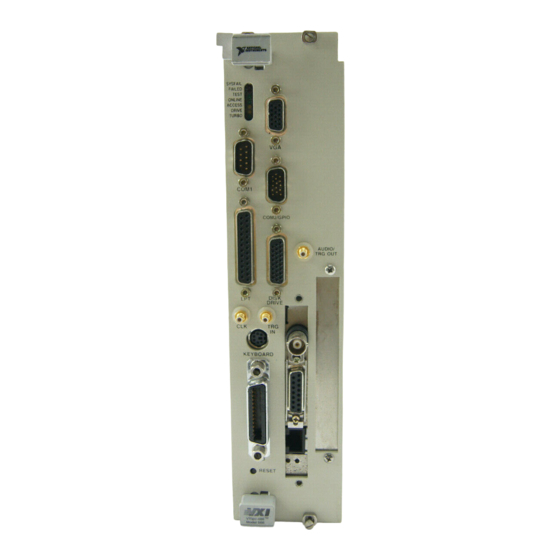
Page 27: Figure 2-10. Vxipc-486 Model 500 Series Front Panel
Figure 2-10 shows the front panel of a two-slot VXIpc-486 equipped with the floppy drive option. Art not available in PDF version of document. Figure 2-10. VXIpc-486 Model 500 Series Front Panel VXIpc-486 Model 500 Series 2-12 © National Instruments Corporation... -
Page 28: Chapter 3 Bios Setup
5. Press <Esc> to exit Setup. If you have not saved your changes, you can do so at this time. 6. Press <Esc> to exit the Extended BIOS Software main window. The VXIpc-486 will restart. © National Instruments Corporation VXIpc-486 Model 500 Series... -
Page 29: Extended Features
5. Press <Esc> to exit Setup. If you have not saved your changes, you can do so at this time. 6. Press <Esc> to exit the Extended BIOS Software main window. The VXIpc-486 will restart. VXIpc-486 Model 500 Series © National Instruments Corporation... -
Page 30: Table 3-2. Extended Bios Configuration Parameters
Table 3-2 shows the default BIOS configuration parameters for the extended features. Table 3-2. Extended BIOS Configuration Parameters Parameter (Extended) Configuration Auto Park Disk Quick Boot Screen Saver Disabled Keyboard Click Keyboard Delay 1/2 s Keyboard Rate 13/s Numlock Boot State Auto © National Instruments Corporation VXIpc-486 Model 500 Series... -
Page 31: National Instruments Software
Appendix A National Instruments Software This appendix summarizes the National Instruments software products you can use with your VXIpc-486 Model 500 Series computer. The VXIpc-486 uses NI-VXI and NI-488.2 software for DOS, Windows, Windows NT, and UNIX. The application software LabVIEW and LabWindows can also run on the VXIpc-486. -
Page 32: Labview And Labwindows
Windows. LabWindows/CVI combines the intuitive graphical user interfaces (GUIs) from the Windows platform with the necessary tools for data acquisition and control, data analysis, and data presentation to give you an integrated system for developing instrumentation software. VXIpc-486 Model 500 Series © National Instruments Corporation... -
Page 33: Appendix B Specifications
• SYSFAIL (red) • FAILED (red) • TEST (green) • ON LINE (green) • ACCESS (yellow) • DRIVE (yellow) • TURBO (green) Front Panel Connectors • • Keyboard • COM1 • COM2 © National Instruments Corporation VXIpc-486 Model 500 Series... -
Page 34: Power Requirements
Refer to ID label Emissions FCC Class A Verified Operating Environment Temperature Refer to ID label Relative Humidity 0% to 95% noncondensing Storage Environment Temperature Refer to ID label Relative Humidity 0% to 100% noncondensing VXIpc-486 Model 500 Series © National Instruments Corporation... -
Page 35: Vmebus Master/Slave
VMEbus Master/Slave • A16/A24/A32 Addressing • D08(EO)/D16/D32 Data Paths • Read-Modify-Write VMEbus System Controller • System Clock (SYSCLK) Driver • System Reset (SYSRESET) Driver • Priority or Round-Robin Arbiter • Bus Timeout Driver © National Instruments Corporation VXIpc-486 Model 500 Series... -
Page 36: Vxibus
• Programmable Interrupter (any combination of seven levels) • Programmable Handler (any combination of seven levels) • Trigger Source/Acceptor (SYNC, SEMI-SYNC, ASYNC, STST protocols) • External Trigger I/O • External CLK10 I/O VXIpc-486 Model 500 Series © National Instruments Corporation... -
Page 37: Appendix C Front Panel Indicators
Failed to boot DOS or waiting to run self-test/VXIINIT In self-test/VXIINIT Failed self-test/ VXIINIT Self-test passed, VXIINIT complete Performing Startup RM operations Online, Startup RM operations complete Failed Failed Startup RM Failed Failed while online © National Instruments Corporation VXIpc-486 Model 500 Series... - Page 38 The yellow DRIVE LED is the hard disk drive access light. It is lit when the internal hard drive is in use. The green TURBO light is not used and is never lit on the VXIpc-486 Model 500 Series computer. VXIpc-486 Model 500 Series © National Instruments Corporation...
-
Page 39: Appendix D Connectors
6-pin Mini DIN TRG IN AUDIO/ TRG OUT KEYBOARD KEYBOARD GPIB RESET Figure D-1. KEYBOARD Connector Table D-1. KEYBOARD Connector Signals Signal Name Signal Description DATA Data Ground Ground +5 volts Clock Ground © National Instruments Corporation VXIpc-486 Model 500 Series... -
Page 40: Vga
Signal Name Signal Description Green Blue n.c. Not Connected Ground Ground Ground Ground n.c. Not Connected Ground n.c. Not Connected n.c. Not Connected HSync Horizontal Sync VSync Vertical Sync n.c. Not Connected VXIpc-486 Model 500 Series © National Instruments Corporation... -
Page 41: Com1
Table D-3. COM1 Connector Signals Signal Name Signal Description Ground RXD* Receive Data TXD* Transmit Data DTR* Data Terminal Ready Ground DSR* Data Set Ready RTS* Ready to Send CTS* Clear to Send Ground © National Instruments Corporation VXIpc-486 Model 500 Series... -
Page 42: Com2/Gpio
GPIO 5 General Purpose Input/Output 5 n.c. not connected GPIO 9 General Purpose Input/Output 9 GPIO 8 General Purpose Input/Output 8 GPIO 6 General Purpose Input/Output 6 GPIO 4 General Purpose Input/Output 4 VXIpc-486 Model 500 Series © National Instruments Corporation... -
Page 43: Lpt
Data Bit 6 Data Bit 7 ACK* Acknowledge BUSY* Device Busy Paper End SLCT Select AUTOFD* Auto Linefeed ERROR* Error INIT* Initialize Printer SLCTIN* Select Input Ground Ground Ground Ground Ground Ground Ground Ground © National Instruments Corporation VXIpc-486 Model 500 Series... -
Page 44: Floppy Disk Drive
Direction Control Ground FSTEP* Step Ground FWD* Write Data FWE* Write Enable FTK0* Track 0 FWP* Write Protect GND* Ground FRDD* Read Data GND* Ground FHS* Handshake DCHG* Diskette Change GND* Ground VXIpc-486 Model 500 Series © National Instruments Corporation... -
Page 45: Gpib
Data Bit 5 DIO6* Data Bit 6 DIO7* Data Bit 7 DIO8* Data Bit 8 REN* Remote Enable Logic Ground Logic Ground Logic Ground Logic Ground Logic Ground Logic Ground Logic Ground © National Instruments Corporation VXIpc-486 Model 500 Series... -
Page 46: External Clk10
Connector Type: SMB DISK DRIVE TRG IN AUDIO/ TRG OUT KEYBOARD GPIB RESET Figure D-8. EXT CLK Connector Table D-8. EXT CLK Connector Signals Signal Description Center TTL CLK10 I/O Signal Shield Ground VXIpc-486 Model 500 Series © National Instruments Corporation... -
Page 47: External Trigger Input
Connector Type: SMB DISK DRIVE TRG IN AUDIO/ TRG OUT KEYBOARD GPIB RESET Figure D-9. TRG IN Connector Table D-9. TRG IN Connector Signals Signal Description Center Trigger Input Signal Shield Ground © National Instruments Corporation VXIpc-486 Model 500 Series... -
Page 48: External Audio/Trigger Output
DRIVE TRG IN AUDIO/ TRG OUT KEYBOARD AUDIO/ TRG OUT GPIB RESET Figure D-10. AUDIO/TRG OUT Connector Table D-10. AUDIO/TRG OUT Connector Signals Signal Description Center Audio/Trigger Output Signal Shield Ground VXIpc-486 Model 500 Series D-10 © National Instruments Corporation... -
Page 49: Vxibus P1 And P2
BG0IN* BG0OUT* BG1IN* BG1OUT* BG2IN* BG2OUT* SYSCLK BG3IN* SYSFAIL* BG3OUT* BERR* DS1* BR0* SYSRESET* DS0* BR1* LWORD* WRITE* BR2* BR3* DTACK* IACK* IACKIN* not connected IACKOUT* not connected IRQ7* IRQ6* (continues) © National Instruments Corporation D-11 VXIpc-486 Model 500 Series... -
Page 50: Table D-12. Vxibus P2 Connector Signals
-5.2 V MODID02 not connected MODID01 not connected TTLTRG0* TTLTRG1* TTLTRG2* TTLTRG3* +5 V TTLTRG4* TTLTRG5* TTLTRG6* TTLTRG7* not connected not connected MODID00 not connected not connected +5 V not connected VXIpc-486 Model 500 Series D-12 © National Instruments Corporation... -
Page 51: Modifying And Installing I/O Expansion Boards
Bright Nickel Plate Alternately, you can modify the blank panels provided with the VXIpc-486/2. Blank panels are also available from National Instruments as an accessory (part number 181300-01). Custom panel design services are available from National Instruments for a nominal fee. -
Page 52: Appendix Fvxipc-486 Plug-In Boards
Figure F-1. Bus Connector Height = 4.2 in. PC Board Top of Board Height = 4.8 in. PC AT Board Figure F-1. Height Comparison of PC Boards Versus PC AT Boards © National Instruments Corporation VXIpc-486 Model 500 Series... -
Page 53: Figure F-2. Installing Pc-Height Boards In A Vxipc-486 System
(the first one installed) must still be PC-height, while the rightmost board (the second one installed) can be PC AT-height. This is an important distinction because there are also restrictions on the length of the boards, as described in the following section. VXIpc-486 Model 500 Series © National Instruments Corporation... -
Page 54: Length Of Vxipc-486 Plug-In Boards
VXIpc-486. A user-defined bracket is required on the expansion boards per National Instruments drawing 181300-01, PC/AT Card Blank Panel. The considerations on the length of the plug-in boards regard support for the back end of the board. -
Page 55: Figure F-4. Vxipc-486 Expansion Kit With No Boards Installed
The first board you install into a VXIpc-486 expansion kit can be less than or equal to 8.2 in. and can be supported using a moveable bracket, as shown in Figure F-6. VXIpc-486 Model 500 Series © National Instruments Corporation... -
Page 56: Figure F-6. First Board 8.2 In. Long Or Less
Figure F-8. Both Boards 8.2 in. Long or Less Both Moveable Brackets Used Figure F-9. First Board Less than 8.2 in. Long, Second Board 8.2 in. Long or Less, but Longer than the First Board © National Instruments Corporation VXIpc-486 Model 500 Series... -
Page 57: Figure F-10. First Board 8.2 In. Long Or Less, Second Board Over One Inch Shorter Than First Board
Figure F-11. First Board 8.2 in. Long or Less, Second Board between 8.2 in. and 13.4 in. Long No Moveable Brackets Used Figure F-12. Both Boards Between 8.2 in. and 13.4 in. Long VXIpc-486 Model 500 Series © National Instruments Corporation... -
Page 58: Figure F-13. Second Board Full 13.4 In. Long
Figure F-14. First Board 8.2 in. Long or Less, Second Board Full 13.4 in. Long No Moveable Brackets Used Figure F-15. First Board between 8.2 in. and 13.4 in. Long, Second Board Full 13.4 in. Long © National Instruments Corporation VXIpc-486 Model 500 Series... -
Page 59: Vxipc-486 Hardware Configuration
Start-End Address Size VXIbus Access A0000–BFFFF 128 KB Super VGA C8000–CFFFF 32 KB VXI A16 Space Window D0000–DFFFF 64 KB For Plug-In PC Expansion Boards E0000–EFFFF 64 KB VXI A24/A32 Space Window © National Instruments Corporation VXIpc-486 Model 500 Series... -
Page 60: Table G-2. Vxipc-486 Model 500 Series I/O Address Map
208H - 21FH Available 220H - 23FH Ethernet Option Default 240H - 277H Available 278H - 27FH Reserved 280H - 2F7H Available 2F8H - 32FH Reserved 330H - 35FH Available 360H - 3FFH Reserved VXIpc-486 Model 500 Series © National Instruments Corporation... -
Page 61: Table G-3. Vxipc-486 Model 500 Series Interrupt Line Use
(Used if Option 920100-xx Installed) Floppy Disk Printer Clock Free for Plug-In PC Boards Free for Plug-In PC Boards GPIB VXI (MIGA, VMEbus Interrupts, Triggers) Reserved Hard Drive Free for Plug-In PC Boards © National Instruments Corporation VXIpc-486 Model 500 Series... -
Page 62: Table G-4. Vxipc-486 Model 500 Series Dma Channel Use
Channel Number Free for Plug-In PC Boards Free for Plug-In PC Boards Floppy Disk Drive Free for Plug-In PC Boards Reserved GPIB Free for Plug-In PC Boards Free for Plug-In PC Boards VXIpc-486 Model 500 Series © National Instruments Corporation... -
Page 63: Configuring The Super Vga Option
3. Use your mouse or the <Alt-Down Arrow> keys to scroll through the options for the Display field. Among several other options you will find three Chips & Technology entries available for the VXIpc-486 after the Super VGA option is installed. © National Instruments Corporation VXIpc-486 Model 500 Series... -
Page 64: Installing The Super Vga Drivers
8. The program prompts you to insert the remaining installation diskettes as needed. After the installation completes, press <Esc> to exit the installation program. 9. Modify the system settings as described previously. VXIpc-486 Model 500 Series © National Instruments Corporation... -
Page 65: Appendix I Common Questions
Perform the following procedure if either the SYSFAIL or FAILED LED remains lit. 1. Power off the mainframe. 2. Remove all other modules from the mainframe. 3. Make sure that the VXIpc-486 jumper settings are set correctly. © National Instruments Corporation VXIpc-486 Model 500 Series... - Page 66 Yes. Although the VXIpc-486 supports the ISA bus, it does not use the bus for communication with the VXIbus backplane. National Instruments has a specialized bus dedicated to the communication to the VXIbus backplane. This bus is a full 32 bits wide, and you can use it for D32 accesses.
- Page 67 Refer to Appendix F, VXIpc-486 Plug-in Boards, for more information. National Instruments offers two SCSI interface options that you can consider when ordering a VXIpc-486. You can order part number 920100-13 for a SCSI adapter without BIOS if you do not intend to boot from an external SCSI hard drive.
- Page 68 15-pin COM2/GPIO connector to a standard 9-pin Subminiature DHD-20 connector. You can try to connect directly to the serial port signals on the COM2/GPIO connector. Refer to Appendix D, Connectors, for the connector pin descriptions. VXIpc-486 Model 500 Series © National Instruments Corporation...
- Page 69 RAM configuration of a two-slot VXIpc-486 module. You must return your VXIpc-486/2 module to National Instruments for SIMM installation or else you will void your warranty. National Instruments recommends the following types of SIMMs for use with the VXIpc-486 Model 500 Series controllers: 1 MB:...
- Page 70 AT-height slot for any ISA bus board (<4.8 inches). If you choose this option, you can use an external floppy drive instead of an internal floppy drive. To arrange to have your VXIpc-486 reconfigured with an AT-height slot, contact your National Instruments Inside Sales Representative or Regional Sales Manager.
- Page 71 The only side effect of disabling the automatic memory check is that you cannot boot off a floppy disk. One advantage is that you can leave a floppy disk in the floppy drive when rebooting the VXIpc-486. © National Instruments Corporation VXIpc-486 Model 500 Series...
-
Page 72: Appendix J Troubleshooting
Appendix I, Common Questions, may also contain the solution to your problem. When you call National Instruments, make sure you have filled out the VXIpc-486 Model 500 Series Hardware and Software Configuration Form in Appendix K. - Page 73 Why does RESMAN hang the system even though VXIINIT works fine? This is most likely caused by a conflict with the master window. See the previous question, Why does RESMAN report warnings/errors about devices that don’t exist in my system? VXIpc-486 Model 500 Series © National Instruments Corporation...
- Page 74 If this procedure did not fix the problem, check to see if you can boot off a floppy DOS disk and then change the drive to C. If the problem persists, your HDD is probably damaged and may need to be reformatted or repaired. © National Instruments Corporation VXIpc-486 Model 500 Series...
- Page 75 The HDD controller may have a problem, or a fuse may have blown, causing the HDD to fail. Reformatting the drive prematurely may not fix the problem but could result in a loss of data. Contact National Instruments for repair information.
-
Page 76: Customer Communication
Filling out a copy of the Technical Support Form before contacting National Instruments helps us help you better and faster. National Instruments provides comprehensive technical assistance around the world. In the U.S. and Canada, applications engineers are available Monday through Friday from 8:00 a.m. to 6:00 p.m. - Page 77 National Instruments for technical support helps our applications engineers answer your questions more efficiently. If you are using any National Instruments hardware or software products related to this problem, include the configuration forms from their user manuals. Include additional pages if necessary.
- Page 78 Completing this form accurately before contacting National Instruments for technical support helps our applications engineers answer your questions more efficiently.
- Page 79 • Super VGA Option Not Installed Factory-Installed User-Installed If installed, give the following information. System Settings Modified for Super VGA? __________________________________________ Super VGA Option Selected __________________________________________ • NI-VXI Version __________________________________________ Use the configuration form in your software manual to describe your NI-VXI software settings. Other Products •...
- Page 80 • Interrupt Level(s) of Other VXI Devices __________________________________________ (Handler/Interrupter) __________________________________________ __________________________________________ __________________________________________ • IEEE 488 Devices (Manufacturer, Model, GPIB Address) __________________________________________ __________________________________________ __________________________________________ __________________________________________ • Any Other Software in System __________________________________________ Please describe your software configuration settings below. _________________________________________________________________________________________ _________________________________________________________________________________________ _________________________________________________________________________________________ _________________________________________________________________________________________ _________________________________________________________________________________________...
- Page 81 Documentation Comment Form National Instruments encourages you to comment on the documentation supplied with our products. This information helps us provide quality products to meet your needs. ™ Title: Getting Started with Your VXIpc -486 Model 500 Series Edition Date:...
-
Page 82: Glossary
American National Standards Institute ASIC Application Specific Integrated Circuit (a semi-custom chip) bytes backplane An assembly, typically a printed circuit board, with 96-pin connectors and signal paths that bus the connector pins. © National Instruments Corporation Glossary-1 VXIpc-486 Model 500 Series... - Page 83 A MXIbus device responds at Logical Address 255 during a priority select cycle. The Resource Manager subsequently assigns it a new logical address, which the device responds to until powered down. VXIpc-486 Model 500 Series Glossary-2 © National Instruments Corporation...
- Page 84 GPIB General Purpose Interface Bus; the industry-standard IEEE 488 bus. GPIO General Purpose Input/Output, a module within the National Instruments TIC chip. GPIOs are used for connecting external signals to the TIC chip for routing/conditioning to the VXIbus trigger lines.
- Page 85 These devices are able to use Word Serial Protocol to communicate with one another through communication registers. MIGA Message-Based Interface Gate Array; a proprietary National Instruments chip. MODID A set of 13 signal lines on the VXI backplane that VXI systems use to identify which modules are located in which slots in the mainframe.
- Page 86 Release When Done seconds Servant A device controlled by a Commander. statically A device for which the logical address cannot be set through software; that configured device is, it is not dynamically configurable. © National Instruments Corporation Glossary-5 VXIpc-486 Model 500 Series...
- Page 87 A functional module that has arbiter, daisy-chain driver, and MXIbus cycle timeout responsibility. Trigger Interface Chip; a proprietary National Instruments chip used for direct access to the VXI trigger lines. The TIC contains a 16-bit counter, a dual 5-bit tick timer, and a full crosspoint switch.
-
Page 88: Index
2-2 to 2-3 configuration procedure for modifying factory CLK10 generation, 2-7 configuration, 2-3 external CLK10, 2-8 Slot 0, 2-5 external CLK10 termination, 2-8 Super VGA option, H-1 to H-2 © National Instruments Corporation Index-1 VXIpc-486 Model 500 Series... - Page 89 CLK10 connector I/O address map (table), G-2 illustration, D-8 I/O expansion boards, modifying and signals (table), D-8 installing, E-1 external CLK10 signal. See also IEEE 488 functionality, B-3 CLK10 signal. VXIpc-486 Model 500 Series Index-2 © National Instruments Corporation...
- Page 90 MODID terminator, factory configuration interrupt line use (table), G-3 for (table), 2-1 ISA bus board monitors. See video display. questions about, I-6 troubleshooting, J-3 National Instruments software, 1-2, A-1 to A-2 jumpers and switches networks CLK10 connecting VXIpc-486, I-4 CLK10 generation, 2-7...
- Page 91 VMEbus System Controller, B-3 questions and answers, I-3 to I-4 VXIbus, B-4 VGA connector operating environment, B-2 illustration, D-2 physical, B-1 to B-2 signals (table), D-2 power requirements, B-2 VMEbus master/slave functionality, B-3 VXIpc-486 Model 500 Series Index-4 © National Instruments Corporation...
- Page 92 I/O expansion boards, E-1 optional equipment, 1-2 optional software, 1-2 plug-in boards height of, F-1 to F-3 length of, F-3 to F-7 questions and answers, I-1 to I-7 troubleshooting, J-1 to J-4 © National Instruments Corporation Index-5 VXIpc-486 Model 500 Series...