Table of Contents

Related Manuals for Trane RTRA Series


Summary of Contents for Trane RTRA Series
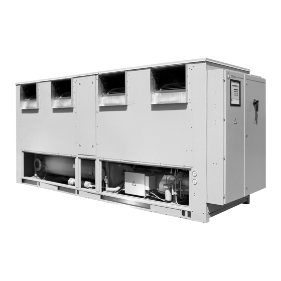
- Page 1 RTRA Screw compressor liquid chillers with centrifugal fans, air cooled Sizes : 107 - 108 - 109 - 110 Installation Operation Maintenance This manual should be used jointly with the manual of the UCM-CLD reference L80 IM 025 E...
-
Page 2: Foreword
Foreword These Installation Operation and Maintenance instruc- They do not contain the full service procedures neces- tions are given as a guide to good practice in the instal- sary for the continued successful operation of this equip- lation, start-up, operation and periodic maintenance by ment. -
Page 3: Table Of Contents
Table of contents Foreword ..............................2 Warranty..............................2 Reception..............................2 General ..............................2 Refrigerant..............................2 Installation General information ..........................4 Installation..............................7 Clearances ..............................9 Lifting procedure ...........................10 Water piping............................10 Freeze protection...........................14 Ductwork recommendations........................15 Wiring ..............................16 Remote CLD ............................18 Operation Operating principles ..........................18 Refrigeration cycle..........................18 Oil system...............................21 Pre-start procedure..........................23 Start-up procedure ..........................24 Shut-down procedure ...........................24 Maintenance... -
Page 4: General Information
When the unit is delivered, verify that it is the correct unit consignee. and that it is properly equipped. Compare the information Notify the Trane sales representative and arrange for repair. which appears on the unit nameplate with the ordering Do not repair the unit, however, until damage is inspect- and submittal information. - Page 5 Figure 2 - Control panel Warning : Panel or box signed by , enclosed parts under voltage. Their opening requires a special key and must be done by qualified engineers. Figure 3 - Starter panel...
- Page 6 Table 1: General data RTRA model 107 LF 108 LF 108 HE 109 LF 109 HE 110 LF 110 HE Compressor size CHHN60CHHN60 CHHB70 CHHB70 CHHB70 CHHB85 CHHB85 CHHB85 CHHB100 CHHB100 CHHB100 Compressor 400/50/3 (A) max. amps Comp. start amps 400/50/3 (A) part-winding Comp.
-
Page 7: Installation
The RTRA series features Trane’s exclusive Adaptive Con- drated, charged, and tested for proper control operation trol logic, which monitors the control variables that govern before shipment. the operation of the chiller unit. Adaptive Control logic can Figures 1 thru 3 show a typical RTRA unit and its compo- correct these variables, when necessary, to optimize oper- nents. - Page 8 Trane sales office. Pre-installation Report any damage incurred during handling or installa- tion to the Trane sales office immediately. An installation check sheet is provided at the end of the manual. Location requirements Noise considerations Locate the unit away from sound-sensitive areas.
-
Page 9: Clearances
Refer to the submittals for unit operating weights. Once in place, the chiller must be level within 1/4" (6mm) over its Figure 6 length and width. The Trane Company is not responsible for equipment problems resulting from an improperly designed or constructed foundation. -
Page 10: Lifting Procedure
Lifting and moving instructions A specific lifting method is recommended as follows : 3. Minimum rated lifting capacity (vertical) of each sling 1. Four lifting points are built into the unit. and speader bar shall not be less than tabulated unit 2. -
Page 11: Water Piping
Unit isolation and leveling Water piping If the unit application requires maximum sound and vibra- Thoroughly flush all water piping to the unit before mak- tion reduction, use one of the two mounting methods out- ing the final piping connections to the unit. lined below : 1. - Page 12 Figure 8 - Suggested piping for typical RTRA evaporator Relief valve Vent Valved pressure gauge Thermometer* Vibration eliminator Gate valve Water strainer Drain Thermometer Vibration Flow eliminator switch** Gate valve Balancing valve * = User option ** = Chilled water flow A pipe strainer should be installed in the entering water line Leaving chilled water piping to prevent water-borne debris from entering the system.
- Page 13 Specific connection and schematic wiring diagrams are 2. To prevent switch fluttering, remove all air from the shipped with the unit. Some piping and control schemes, water system. particularly those using a single water pump for both chilled and hot water, must be analyzed to determine how and/or Note : The UCM-CLD provides a 6 second time delay if a flow sensing device will provide desired operation.
-
Page 14: Freeze Protection
Société Trane war- If heat tape is not used, add a nonfreezing, low tempera- ranty specifically excludes liability for corrosion, erosion ture, corrosion inhibiting, heat transfer fluid to the or deterioration of Trane equipment. -
Page 15: Ductwork Recommendations
Ductwork recommendations Free discharge or abrupt discharge into a plenum will be Caution : When attaching supply ductwork to con- avoided, each fan discharge should have a mimum of 1,5 denser inlet, ensure no fasteners pierce the coil. meter duct to avoid an excess of pressure drop. On the units with 3 fans, each fan can be individually ducted or the single fan will be ducted with a ‘’pants’’... -
Page 16: Wiring
Wiring Remote CLD Mounting All hardware (tools, screws,etc...) is to be field supplied. Fig- ure 11 shows the remote CLD panel and the electrical access Power supply knockouts at the bottom and top of the panel. Remove the All power supply wiring must be sized and selected knockouts that will be used for wire entry, prior to mount- according by the project engineer in accordance with the ing the panel. -
Page 17: Remote Cld
Remote CLD Panel Wiring Note : A field supplied 24V, 40VA separation trans- The Remote CLD requires a 24 V power source and a shield- former with electrostatic screen must be used as a ed, twisted-pair wire between the panel and the local CLD. power supply for the Remote CLD. -
Page 18: Operation
Screw compressor air-cooled chillers equipped cooled chiller is conceptually identical to that of the with microcomputer-based control systems. Trane reciprocating air-cooled units. The major differ- - Unit Control Module (UCM-CLD) ence is that the Screw compressor unit uses helical... - Page 19 Figure 14 - Refrigeration system for CHHB compressors Compressor Drier filter Discharge line Electronic expansion valve Safety valve (according to local code) Evaporator HP pressure switch EVP refrigerant entering temperature sensor Discharge stop valve (option) EVP refrigerant leaving temperature sensor Oil separator Water inlet connection Oil separator vent...
- Page 20 Cycle description compressor housing. The rotor contact each other at the point where the driving action between the male and Vaporized refrigerant leaves the evaporator and is drawn female rotors occurs. Oil is injected along the top of the into the compressor. Here it is compressed and leaves compressor rotor section, coating both rotors and the the compressor as a mixture of hot gas and oil (which compressor housing interior.
-
Page 21: Oil System
Figure 15 - Typical CHHB compressor Oil system operation Compressor bearing oil supply Oil is injected into the bearing housings located at each Overview end of both the male and fermale rotors. Each bearing Oil that collects in the b ottom of the oil separator is at housing is vented to compressor suction, so that oil leav- condensing pressure during compressor operation ;... - Page 22 Slide valve movement Condenser fan staging Movement of the slide valve piston determines slide The RTRA series offers either the standard or the low valve position which, in turn, regulates compressor ambient and extra low ambient configuration on the low capacity.
-
Page 23: Pre-Start Procedure
Pre-start procedures General water flow and check water pressure drop through the When installation is complete, but prior to putting the unit evaporator are conform to the order specifications. into service, the following pre-start procedures must be Refer to figure 9. reviewed and verified correct : 12) Adjust chilled water flow switch (if installed) for prop- 1) Inspect all wiring connections to be sure they are clean... -
Page 24: Start-Up Procedure
(backseated) before starting the com- If superheat is normal but subcooling is not, contact a qual- pressors. ified Trane service technician. Caution : To prevent compressor damage, do not oper- Unit shutdown procedures ate the unit until all refrigerant and oil line service valves are opened. - Page 25 Extended shutdown procedure The following procedure is to be followed if the system is Caution : The compressor sump heaters must be ener- to be taken out of service for an extended period of time, gized for a minimum of 24 hours prior to unit opera- eg.
-
Page 26: Maintenance
Maintenance Periodic maintenance Annual maintenance - Perform all weekly and monthly maintenance proce- General dures. Perform all maintenance procedures and inspections at - Have a qualified service technician check the setting and the recommended intervals. This will prolong the life of the function of each control. -
Page 27: Chemically Cleaning The Evaporator
Chemically cleaning the evaporator The length of time the chemicals are used The chilled water system is a closed-loop and therefore Any safety precautions and handling instructions should not accumulate scale or sludge. If the chiller becomes fouled, first attempt to dislodge the material by Service pumpdown backflushing the system. -
Page 28: Start Log Sheet
Start log sheet Job Name Elevation Above Job Location Sea Level Unit Model No. S.O. No. Unit Serial No. Nameplate Volt Ship Date Comp Model No. Serial No. Nameplate RLA Cond Fan Motor RLA Evap Design Actual Heat Tape Volt Pres. -
Page 29: Installation Checklist
Check available cooling charge (50% of rated installation load) ❏ Check with other trades handling installation works Comments : ............................................................................................................................................................................................Signature : ............Company : ..................Order N° ....................................Work site : .................................... Please return to your local Trane Service Agency... - Page 30 Notes...
- Page 31 Notes...
-
Page 32: Safety Recommendations
Société Trane - Société Anonyme au capital de 41 500 000 F - Siège Social : 1, rue des Amériques - 88190 Golbey - France - Siret 306 050 188-00011 - RCS Epinal B 306 050 188 - Numéro d'identification taxe intracommunautaire : FR 83 306050188...