Advertisement
Save these instructions for future use!
FAILURE TO READ AND FOLLOW ALL INSTRUCTIONS
CAREFULLY BEFORE INSTALLING OR OPERATING
THIS CONTROL COULD CAUSE PERSONAL INJURY
AND/OR PROPERTY DAMAGE.
APPLICATIONS
THERMOSTAT APPLICATION GUIDE
Description
Heat Pump (No Aux. or Emergency Heat)
Heat Pump (with Aux. or Emergency Heat)
Systems with up to 2 Stages Heat, 2 Stages Cool
Heat Only Systems (with optional fan switch)
Millivolt Heat Only Systems – Floor or Wall Furnaces
Cool Only Systems
Gas or Oil Heat
Electric Furnace
Hydronic (Hot Water) Zone Heat – 2 Wires
Hydronic (Hot Water) Zone Heat – 3 Wires
SPECIFICATIONS
Electrical Rating:
Battery Power .................................................... mV to 30 VAC, NEC Class II, 50/60 Hz or DC
Input-Hardwire ................................................... 20 to 30 VAC
Terminal Load ........................................................... 1.5 A per terminal, 2.5A maximum all terminals combined
Setpoint Range ......................................................... 45° to 90°F (7° to 32°C)
Differential (Single Stage) ......................................... Heat 0.6°F; Cool 1.2°F (adjustable)
Differential (Heat Pump) ........................................... Heat 1.2°F; Cool 1.2°F (adjustable)
Operating Ambient .................................................... 32° to +105°F (0° to +41°C)
Operating Humidity ................................................... 90% non-condensing max.
Shipping Temperature Range ................................... -4° to +150°F (-20° to +65°C)
Dimensions Thermostat ............................................ 3.4"H x 4.4"W x 1.3"D
CAUTION
!
To prevent electrical shock and/or equipment damage,
disconnect electric power to system at main fuse or
circuit breaker box until installation is complete.
Index
Installation
Wiring Connections
Thermostat Quick Reference
Installer Confi guration Menu
Operating Your Thermostat
Programming
Troubleshooting
80 Series Thermostat with
Automatic Heat/Cool Changeover Option
Single Stage, Multi-Stage or Heat Pump
Installation and Operating Instructions for Model:
Model
1F85-0422
1F83-0422
Yes
Yes
Yes
Yes
Yes
Yes
Yes
Yes
Yes
Yes
Yes
ATTENTION: MERCURY NOTICE
This product does not contain mercury. However, this
product may replace a product that contains mercury.
Mercury and products containing mercury must not be
discarded in household trash. Do not touch any spilled
Page
mercury. Wearing non-absorbent gloves, clean up any
spilled mercury and place in a sealed container. For proper
2
disposal of a product containing mercury or a sealed
2
container of spilled mercury, place it in a suitable shipping
3
container and send it to:
4
6
6
8
www.white-rodgers.com
Programming Choices
5/1/1 Day
5/2 Day
Non-Programmable
Non-Programmable
1F83-0422 Thermostat
White-Rodgers
2895 Harrison Street
Batesville, AR 72501
PART NO. 37-6894A
0735
1
Advertisement
Table of Contents

Related Manuals for White Rodgers 1F83-0422


Summary of Contents for White Rodgers 1F83-0422
-
Page 1: Specifications
Model Programming Choices 1F85-0422 5/1/1 Day 1F83-0422 1F83-0422 Thermostat ATTENTION: MERCURY NOTICE This product does not contain mercury. However, this product may replace a product that contains mercury. Mercury and products containing mercury must not be discarded in household trash. Do not touch any spilled Page mercury. -
Page 2: Wiring Connections
Figure 2 – Thermostat base and rear view of thermostat Mounting Hole Place Level across Mounting Tabs (for appearance only) Refer to 37-6895 for 1F83-0422/1F85-0422 wiring diagram specifi cations. TERMINAL DESIGNATION DESCRIPTIONS Terminal Designation Description W/E ...Heat Relay/Emergency Heat Relay (Stage 1) W2 ...2nd Stage Heat (3rd Stage Heat in HP 2) -
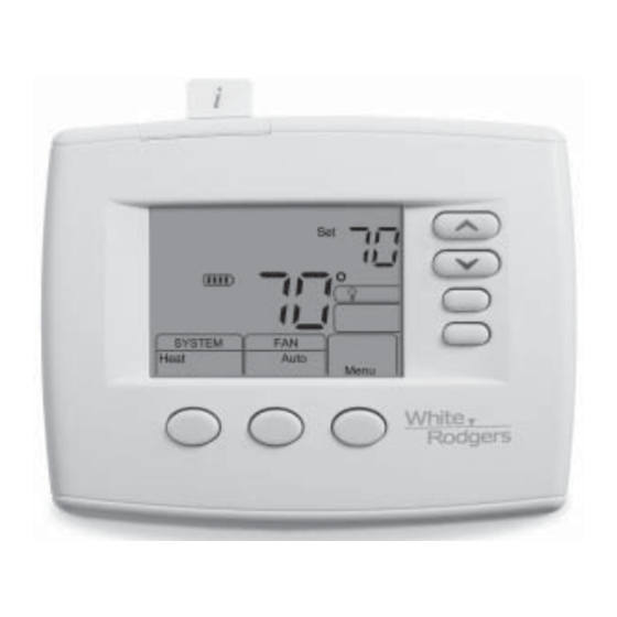
Page 3: Home Screen Description
THERMOSTAT QUICK REFERENCE Home Screen Description Displays the power level of the 2 “AA” batteries: indicates good power level indicates batteries at about half power. “Change batteries are low and should be replaced with 2 new premium brand “AA” Alkaline batteries. (See page 2 for more details) Figure 4 –... -
Page 4: Installer/Configuration Menu
INSTALLER/CONFIGURATION MENU Press the Menu button for at least 5 seconds. The display will show item #1 in the table below. Press Menu to advance to the next menu item. Press to change a menu item. Shaded items available on 1F85 model only. PRESS DISPLAYED MENU... - Page 5 INSTALLER/CONFIGURATION MENU This control can be confi gured for: MS 2 – Multi-Stage System (no heat pump) HP 1 – Heat Pump with one stage of compressor HP 2 – Heat Pump with two stage compressor or two compressor system, Gas or Electric backup SS 1 –...
-
Page 6: Operating Your Thermostat
INSTALLER/CONFIGURATION MENU 21) Select Filter Replacement Reminder and Set Run Time – Select the “Change Filter” reminder On or OFF. If selected On, press MENU to select the time period from 25 to 1975 hours in 25 hours increments. In a typical system, 200 hours (default) of run time is approximately 30 days. - Page 7 PROGRAMMING (For Programmable Model Only) Repeat steps 2 through 8 until all of the program times and temperatures are set for all program periods on that day. 10) Press Schedule to the next day and repeat steps 2 through 9. 11) When programming is complete and all of the times and temperatures match your desired heating schedule, press Run Schedule.
-
Page 8: Reset
TROUBLESHOOTING Reset Operation Note: When thermostat is reset, installer confi guration menu settings and programming will reset to factory settings. If a voltage spike or static discharge blanks out the display or causes erratic thermostat operation, you can reset the thermostat by removing the wires from terminals R and C (do not short them together) and removing batteries for 2 minutes.