Advertisement
Operator: Save these instructions for future use!
FAILURE TO READ AND FOLLOW ALL INSTRUCTIONS CAREFULLY
BEFORE INSTALLING OR OPERATING THIS CONTROL COULD CAUSE
PERSONAL INJURY AND/OR PROPERTY DAMAGE.
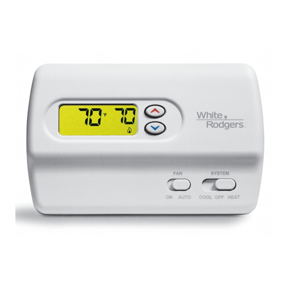
Your new White-Rodgers Digital Thermostat uses the technol-
ogy of a solid-state microcomputer to provide precise time/
temperature control. This thermostat offers you the flexibility to
design heating and cooling programs that fit your needs.
Features:
• Simultaneous heat and cool setpoint storage
• Pre-set temperature control
• LCD continuously displays setpoint and room temperature
This thermostat is intended for use with a low voltage system; do
not use this thermostat with a line voltage system. If in doubt
about whether your wiring is millivolt, line, or low voltage, have
it inspected by a qualified heating and air conditioning contractor
or electrician.
Do not exceed the specification ratings.
All wiring must conform to local and national electrical codes and
ordinances.
This control is a precision instrument, and should be handled
carefully. Rough handling or distorting components could cause
the control to malfunction.
CAUTION
!
To prevent electrical shock and/or equipment damage,
disconnect electric power to system at main fuse or
circuit breaker box until installation is complete.
ELECTRICAL DATA
Electrical Rating:
20 to 30 VAC 50/60 Hz. or D.C.
0.05 to 1.5 Amps (Load per terminal)
1.5 Amps Maximum Total Load (All terminals combined)
THERMAL DATA
Setpoint Temperature Range:
45°F to 90°F (7°C to 32°C)
Operating Ambient Temperature Range:
32°F to 105°F
Operating Humidity Range:
0 to 90% RH (non-condensing)
Shipping Temperature Range:
-4°F to 150°F
WHITE-RODGERS
EMERSON ELECTRIC CO.
9797 REAVIS ROAD
ST. LOUIS, MISSOURI 63123-5398
www.white-rodgers.com
Non-Programmable Electronic Digital
Multi-Stage Thermostat
INSTALLATION AND OPERATION INSTRUCTIONS
• Backlit display when any key is pushed
• °F/°C convertibility
• Temperature range 45° to 90°F
• R, C, W, W2, G , Y and Y2 terminals
• Optional C terminal (Dual Power option)
• Setpoint storage in case of power loss
• 2 "AA" Energizer
Do not use on circuits exceeding specified voltage.
Higher voltage will damage control and could cause
shock or fire hazard.
Do not short out terminals on gas valve or primary
control to test. Short or incorrect wiring will damage
thermostat and could cause personal injury and/or
property damage.
Thermostat installation and all components of the
system shall conform to Class II circuits per the NEC
code.
APPLICATIONS
For use with:
• Heat/cool systems with up to two stages heat,
two stages cool
DO NOT USE WITH:
• Millivolt systems
• Systems exceeding 30 VAC and 1.5 amps
• 3-wire zoned hydronic heating systems
Printed in U.S.A.
1F83-261
DESCRIPTION
®
alkaline batteries included
PRECAUTIONS
WARNING
!
SPECIFICATIONS
PART NO. 37-6321A
0143
Advertisement

Related Manuals for White Rodgers 1F83-261


Summary of Contents for White Rodgers 1F83-261
-
Page 1: Specifications
-4°F to 150°F WHITE-RODGERS EMERSON ELECTRIC CO. 9797 REAVIS ROAD ST. LOUIS, MISSOURI 63123-5398 www.white-rodgers.com 1F83-261 Non-Programmable Electronic Digital Multi-Stage Thermostat INSTALLATION AND OPERATION INSTRUCTIONS • Backlit display when any key is pushed • °F/°C convertibility • Temperature range 45° to 90°F •... -
Page 2: Check Thermostat Operation
INSTALLATION REMOVE OLD THERMOSTAT 1. Shut off electricity at the main fuse box until installation is complete. Ensure that electrical power is disconnected. 2. Remove the front cover of the old thermostat. With wires still attached, remove wall plate from the wall. If the old thermostat has a wall mounting plate, remove the thermo- stat and the wall mounting plate as an assembly. -
Page 3: Wiring
The following wiring diagrams show typical terminal identification and wiring. For proper installation, refer to the original manufacturer’s instructions. Relay contacts shown are thermostatically operated. Heat Compressor Relay Contactor Stage 1 Stage 2 Compressor Contactor Relay Stage 1 Figure 2. Typical wiring diagram for single transformer systems CUT AND TAPE OFF! Compressor... -
Page 4: Configuration Menu
Heating System 1. Move SYSTEM switch to HEAT position. If the heating system has a standing pilot, be sure to light it. 2. Press to adjust thermostat setting above room tempera- ture. The heating system should begin to operate. 3. Both stages of the heating system should begin to operate when the setpoint is set greater than 3°F above ambient. -
Page 5: Setting The Thermostat
Step Press Button(s) Displayed (Factory Default) Set SYSTEM switch to OFF Set SYSTEM switch to HEAT or COOL 2) Select FA or SL (Fast or Slow) Heating Cycle Rate - The FA setting is frequently used for gas, oil or electric heat. The SL setting produces a longer heating cycle which is nor- mally for hot water or steam (hydronic) systems. -
Page 6: Reset Operation
TROUBLESHOOTING Symptom No Heat/No Cool/No Fan (common problems) No Heat No Cool Heat, Cool or Fan Runs Constantly. Furnace Cycles Too Fast or Too Slow (narrow or wide temperature swing) Cooling Cycles Too Fast or Too Slow (narrow or wide temperature swing) Thermostat Setting and Thermometer Disagree Blank Display and/or Keypad Not...