Fostex DV40 Service Manual
Dvd master recorder
Hide thumbs
Also See for DV40:
- Operation manual (182 pages) ,
- Supplement owner's manual (24 pages) ,
- Brochure & specs (8 pages)
Advertisement
Quick Links
Advertisement

Related Manuals for Fostex DV40


Summary of Contents for Fostex DV40
- Page 1 Service Manual Model DVD MASTER RECORDER...
- Page 2 CAUTION: CAUTION TO PREVENT ELECTRIC SHOCK, MATCH RISK OF ELECTRIC SHOCK WIDE BLADE OF PLUG TO WIDE SLOT, DO NOT OPEN FULLY INSERT. ATTENTION: CAUTION: TO REDUCE THE RISK OF ELECTRIC SHOCK, POUR ÉVITER LES CHOCS ÉLECTRIQUES, DO NOT REMOVE COVER (OR BACK). INTRODUIRE LA LAME LA PLUS LARGE DE NO USER-SERVICEABLE PARTS INSIDE.
-
Page 3: Table Of Contents
* Service mode, parts list and circuit diagrams are given in this manual to assist the service technician in maintaining Model DV40. * The following accessories are supplied with DV40 as the standard accessories. Owner's manual : 8288486000 (for export model) -
Page 4: Specifications
Service Manual 1. SPECIFICATIONS SPECIFICATION UNIT 0 dBV = 1 Vr.m.s, 0 dBu = 0.775 Vr.m.s. INPUT & OUTPUT Reference Level -12 / -18 / -20 dB (Switchable by SETUP menu) Analog Input (TR1 ~ 4) Connector XLR-3-31 type (Pin 1: GND, Pin 2: HOT, Pin 3: COLD) Input impedance 10 kΩ... - Page 5 Connector BNC type 9P-REMOTE (RS-422) * Connector D-DUB 9-pin Protocol Comply to SONY 9-pin (P2) protocol DV40 works as a controlled device only. Pin assignment Refer to the drawing on page 7. 15P-REMOTE (RS-422) * Connector D-DUB 15-pin Protocol Comply to SONY 9-pin (P2) protocol DV40 works as a controlled device only.
- Page 6 Service Manual DIMENSIONS 141 (H) x 482 (W) x 369 (D) mm WEIGHT 7.4 kg USAGE CONDITION Horizontal, continuous operation POWER SUPPLY 100 V AC 120 V AC UK / EUR 230 V AC POWER CONSUMPTION 50 W STANDARD ENVIRONMENT 20 ±...
- Page 7 Service Manual GPI Port Pin Assignment OUTPUT INPUT GPI Output GPI Input Pin Assignment Pin Assignment Pin 1 Pin 1 Pin 2 STOP Pin 2 Cue Point 2 Event Output Pin 3 PLAY Pin 3 Cue Point 1 Event Output Pin 4 >>...
-
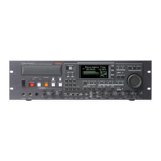
Page 8: Controls, Indicators And Connectors
Service Manual 2. CONTROLS, INDICATORS & CONNECTORS... - Page 9 Service Manual...
-
Page 10: Software Update
There are flash ROMs mounted on the CPU Module PCB assy (16M), Display PCB assy (8M inside the Display CPU) and Ether Card PCB assy (8M). The DV40 software can be updated using a CD-ROM or DVD-RAM disk put into the DV40 internal DVD-RAM drive. - Page 11 [CAUTION] 1. Please make sure to power off and then back on DV40 and initialize it (See page 14.) after updating the software. 2. When using a DVD-RAM disk for updating the software, please make sure to format it by UDF1.5. If the disk is formatted by UDF2.0, it might not be correctly recognized by a Macintosh computer.
-
Page 12: Service Mode
4-1. Putting DV40 into Service Mode The way to put DV40 into Service Mode is to press the [SETUP] key while holding down the [STOP] key. With this operation, optional menus “Self Check Sure?”, “Memory Initial?” and “Flash ROM?” will be additionally displayed between the “Running Time”... - Page 13 -INT- FORMAT 4-3. Self Check Mode The Self Check mode helps you check if DV40 works properly or not and which circuits are causing a problem. In this mode, the following circuit are tested in order. • RS422 9-pin circuit •...
- Page 14 GPI IN - GPI OUT • PS/2 keyboard To KEYBOARD connector • PS/2 mouse To MOUSE connector <Connection on DV40 Front Panel side> DV D M A S T E R R E C O R D E R OPEN/CLOSE DISP SETUP...
- Page 15 ∞ CLOCK -0.1% 2018 6 5 4 3 2 1 0 OL -INT- FORMAT If DV40 works properly, the followings appear on the FL display and it automatically goes back to the normal display. DIGITAL DIGITAL ∞ ∞ CLOCK CLOCK...
- Page 16 Service Manual DIGITAL DIGITAL ∞ ∞ CLOCK CLOCK -0.1% 2018 2018 6 5 4 3 2 1 0 OL 6 5 4 3 2 1 0 OL -INT- -INT- FORMAT FORMAT DIGITAL DIGITAL ∞ CLOCK CLOCK -0.1% 2018 6 5 4 3 2 1 0 OL -INT- -INT- FORMAT...
- Page 17 Service Manual 4-3-2. Error display examples The followings are error display examples. Please remember that pressing the [ENTER/YES] key will retry each checking item and pressing the [EXIT/NO] key will skip each checking item and go on to the next one. •...
- Page 18 (e.g. power shutdown, blackout). The Flash ROM Card PCB allows to boot up DV40, copy the system software in the Flash ROM Card PCB to the Flash ROM on the CPU Module and Ether Card PCBs using this “Flash ROM”...
- Page 19 In this condition, DV40 is booted up using the program inside the Flash ROM on the Flash ROM PCB. 5. Put DV40 into the Service Mode by pressing the [SETUP] key while holding down the [STOP] key and select the “Flash ROM?” menu.
- Page 20 Service Manual 4-7. Display / Key / SW Test This mode tests if all the FL display segments, LEDs, keys and switches on the DV40 front panel are correctly working. 4-7-1. FL Display and LED Test Press the [SHIFT], [SETUP] and [SOURCE IN] key.
- Page 21 Service Manual DV D M A S T E R R E C O R D E R OPEN/CLOSE DISP SETUP FILE SEL VARI PITCH SHUTTLE TIME UTILITY DIRECTORY DISP LEVEL SKIP/CURSOR SHIFT MARGIN EXIT/NO ENTER/YES RESET DRIVE TAPE MODE CHASE LIST PLAY POWER...
- Page 22 FORMAT In this condition, if a key on the DV40 front panel is pressed, the corresponding reference number will be displayed on the FL display. Up to 5 reference numbers can be displayed when multiple keys are pressed at a time. The number of keys pressed at a time is also displayed at the far right of the FL display.
- Page 23 4-7-3. Toggle SW Function Test There are five toggle switches placed on the lower section of DV40 front panel. This mode checks if they are correctly working or not by displaying the corresponding toggle switch position among up ( ), center ( ) and down ( ). In order to enter this test mode, press the [SHIFT], [SETUP] and [DEST IN] key.
-
Page 24: Exploded View, Pcb Assembly And Parts List
Service Manual 5. EXPLODED VIEW, PCB ASSEMBLY AND PARTS LIST DV40 OVERALL EXPLODED VIEW 1 & PARTS LIST Ref. No. Part No. Description 8212 7000 00 Panel, control, DV40 8212 3860 00 Lens, LED, triangle 8212 3850 00 Lens, LED, square... - Page 25 Service Manual...
- Page 26 Service Manual DV40 OVERALL EXPLODED VIEW 2 & PARTS LIST Ref. No. Part No. Description 8221 3660 00 Panel, rear, L, DV40 8274 3320 00 PCB assy, AD, DV40 8274 3330 00 PCB assy, DA, DV40 8216 7680 00 Shield, XLR, A, DV40...
- Page 27 Service Manual...
- Page 28 Service Manual...
- Page 29 Service Manual...
- Page 30 Service Manual...
- Page 31 Service Manual...
- Page 32 Service Manual • Parts Side of AD PCB -10dBV +4dBu -10dBV +4dBu J201 J101 S201 S101 R215 R115 TRIM TRIM C208 R203 R103 R235 C108 R135 R236 R136 R204 R104 U101 U201 C207 C107 INPUT VOL INPUT VOL C202 R237 C102 R137 R133...
- Page 33 Service Manual • Foil Side of AD PCB...
- Page 34 Service Manual • Parts Side of DA PCB TRIM TRIM D251 D151 R277 R177 R291 Q154 R285 R185 C269 C169 PHONES C175 C276 C176 C265 C165 C170 C270 R276 R176 C157 C257 C258 C158 Q251 Q151 C183 C283...
- Page 35 Service Manual • Foil Side of DA PCB...
- Page 36 Service Manual • Parts Side of ETHER CARD PCB D402 D401 D400 U002 U001 C421 C420 R001 R002 R003 R419 C416 R420 C007 C006 C417 C419 C005 C008 R421 R422 L400 C001 C004 L401 C407 C200 C209 C408 R418 C402 C409 R007 R203...
- Page 37 Service Manual • Foil Side of ETHER CARD PCB...
- Page 38 Service Manual • Parts Side of TC CARD PCB MAIN...
- Page 39 Service Manual • Foil Side of TC CARD PCB...
- Page 40 Service Manual • Parts Side of POWER PCB ER2810 D S C...
- Page 41 Service Manual • Foil Side of POWER PCB...
- Page 42 Service Manual...
- Page 43 Service Manual...
- Page 44 Service Manual...
- Page 45 TAPE MODE CHASE LIST PLAY TC SETUP EDIT STOP PLAY REWIND F FWD RECORD PCB,CTRL KEY,DV40 • Parts & Foil Side of PS2 PCB • Parts & Foil Side of JOG PCB J401 J402 MOUSE KEY BOARD W401 PCB,PS/2,DV40 8252506107...
- Page 46 Service Manual C101 C102 R103 R102 R105 R104 C201 C202 R203 R202 R205 R204...
- Page 47 • Parts & Foil Side of VIDEO SYNC IN PCB S201 S101 J103 J102 R201 R110 THRU VIDEO L101 D101 D102 C102 R202 R105 TC CARD R101 C104 J201 R102 C103 J101 R103 U101 W201 MAIN 8252508102 PCB,VIDEO SYNC IN,DV40...
- Page 48 • CPU MODULE PCB assy CAPACITORs Ref. No. Part No. Description ALU = Electrolytic type 8274 3230 00 PCB Assy, CPU MODULE, DV40 CER = Ceramic type B00001 8251 7120 00 PCB, CPU MODULE, DV40 Ref. No. Part No. Description C00001~03 8233 3221 07 ST, ALU, 16V, 100µF, 20%, MVY...
- Page 49 Description Ref. No. Part No. Description R00001, 02 8230 5101 02 ST, carbon, 1/15W, 1kΩ, 5% 8274 3240 00 PCB Assy, MAIN, DV40 R00003~05 B00002 8252 5052 01 Plain PCB, MAIN, DV40 R00006 8230 5101 01 ST, carbon, 1/15W, 100Ω, 5% R00007 8230 5101 03 ST, carbon, 1/15W, 10kΩ, 5%...
- Page 50 Service Manual Ref. No. Part No. Description Ref. No. Part No. Description R00139, 40 8230 5100 00 ST, carbon, 1/15W, 0Ω, 5% C00094 R00141, 42 8230 5104 70 ST, carbon, 1/15W, 47Ω, 5% C00095~98 8233 5131 03 ST, CER, 50V, 0.01µF, 15%, CC11R R00143~46 8230 5101 03 ST, carbon, 1/15W, 10kΩ, 5% C00099 8233 5151 04 ST, CER, 25V, 0.1µF, +80, CC11F...
- Page 51 DIODEs Ref. No. Part No. Description Ref. No. Part No. Description 8274 3250 00 PCB Assy, WORD I/O, DV40 D00201 8234 5028 00 ST, DAN202K B00001 8252 5051 02 Plain PCB, WORD I/O, DV40 D00202 8234 5029 00 ST, DAP202K-T146...
- Page 52 8274 3290 00 PCB Assy, JOG, DV40 Ref. No. Part No. Description B00001 8252 5060 04 Plain PCB, JOG, DV40 8274 3270 00 PCB Assy, CTRL KEY, DV40 B00001 8252 5060 02 Plain PCB, CTRL KEY, DV40 Ref. No. Part No. Description...
- Page 53 Ref. No. Part No. Description R00301 8240 2130 01 POT, PL, RT 9, 10kΩA, RK0971220 8274 3300 00 PCB Assy, INPUT VR, DV40 R00302~07 8230 5102 03 ST, carbon, 1/15W, 20kΩ, 5% B00001 8252 5061 05 Plain PCB, INPUT VR, DV40...
- Page 54 Ref. No. Part No. Description R00203, 04 8230 5131 03 ST, metal, 1/8W, 10kΩ, 1%, MELF 8274 3320 00 PCB Assy, AD, DV40 R00205 8230 5137 52 ST, metal, 1/8W, 7.5kΩ, 1%, MELF B00001 8252 5272 01 Plain PCB, AD, DV40...
- Page 55 Ref. No. Part No. Description C00207, 08 8233 5131 03 ST, CER, 50V, 0.01µF, 15%, CC11R 8274 3330 00 PCB Assy, DA, DV40 C00209 8233 3341 06 ST, ALU, 25V, 10µF, 20%, MVA B00001 8252 5071 02 Plain PCB, DA, DV40...
- Page 56 Service Manual Ref. No. Part No. Description Ref. No. Part No. Description R00067~70 8230 5154 73 ST, carbon, 1/8W, 47kΩ, 5%, MELF C00053 8233 0491 06 ST, ALU, 16V, 10µF, 20%, MV R00073, 74 C00054 8233 5151 04 ST, CER, 25V, 0.1µF, +80, CC11F R00075 8230 5154 72 ST, carbon, 1/8W, 4.7kΩ, 5%, MELF C00056...
- Page 57 Ref. No. Part No. Description R00016 8230 5101 03 ST, carbon, 1/15W, 10kΩ, 5% 8274 3350 00 PCB Assy, TC CARD, DV40 R00017 8230 5102 24 ST, carbon, 1/15W, 220kΩ, 5% B00001 8252 5071 02 Plain PCB, TC CARD, DV40 R00018 8230 5101 01 ST, carbon, 1/15W, 100Ω, 5%...
- Page 58 Service Manual Ref. No. Part No. Description Ref. No. Part No. Description C00046 8233 0491 06 ST, ALU, 16V, 10µF, 20%, MV R00030 8230 5101 01 ST, carbon, 1/15W, 100Ω, 5% C00047~51 8233 5131 03 ST, CER, 50V, 0.01µF, 15%, CC11R R00031 8230 5102 71 ST, carbon, 1/15W, 270Ω, 5% C00052...
- Page 59 Part No. Description Ref. No. Part No. Description 8274 3360 00 PCB Assy, VIDEO SYNC IN, DV40 8274 3370 00 PCB Assy, ETHER CARD, DV40 B00001 8252 5081 02 Plain PCB, VIDEO SYNC IN, DV40 B00001 8251 7131 00 Plain PCB, ETHER CARD, DV40 Ref.
- Page 60 Part No. Description C00008 8233 0492 26 ST, ALU, 6.3V, 22µF, 20%, MV 8274 3380 00 PCB Assy, POWER, DV40 C00009~12 8233 5124 71 ST, CER, 50V, 470pF, 5%, CC11SL B00001 8251 9745 01 Plain PCB, POWER, DV40 C00020, 21 C00030~34 8233 5124 71 ST, CER, 50V, 470pF, 5%, CC11SL C00100~04 8233 5151 04 ST, CER, 25V, 0.1µF, +80, CC11F...
- Page 61 Service Manual Ref. No. Part No. Description Ref. No. Part No. Description D00002, 03 8234 1085 00 VT, fast recovery, D1NL40 C00025 8232 3491 03 VT, PES, 630V, 0.01µF, 10%, D00004 8234 1080 00 V, 200V, 5.0A, MA649 ECQ-EKF3 D00005 8234 1084 00 VT, schottky, EK03W C00026 8232 8181 04 VT, CER, 25V, 0.1µF, +80-20%, YF...
- Page 62 8276 7760 50 Cable assy, 6P, WHTMT/F-MT/BS, L500 • SW POWER PCB assy Ref. No. Part No. Description 8274 3400 00 PCB Assy, SW POWER, DV40 B00001 8251 9743 02 Plain PCB, SW POWER, DV40 MISCELLANEOUS Ref. No. Part No.
-
Page 63: Circuit Diagrams
Service Manual 6. CIRCUIT DIAGRAMS A+18 A+18 A+18 A+18 D+3.3 D+3.3 DGND AGND AGND AGND AGND DGND A-18 A-18 A-18 A-18 A+5D A+5D A+5D A+5D D+12 /LINE_MUTE /LINE_MUTE /LINE_MUTE /LINE_MUTE D+12 REF-18 REF-18 REF-18 REF-18 D+12 REF-20 REF-20 REF-20 REF-20 /MUTE /MUTE /MUTE... - Page 64 Service Manual FRONT...
- Page 65 Service Manual...
- Page 66 Service Manual...
- Page 67 Service Manual FRONT FRONT HDD 2.5inch -- option DD[0-15] (SLAVE) 10KJ 74VHCT32 /ATA_RST /ATA_RST5 DGND DD[7] DGND DD[8] DD[6] DMARQ DD[9] DD[5] DD[10] DD[4] IORDY DD[11] DD[3] DD[12] DD[2] INTRQ DD[13] DD[1] DD[14] DD[0] 74VHCT32 DQMUU DD[15] 5.6KJ KEYPIN(nc) DMARQ <<...
- Page 68 Service Manual...
- Page 69 Service Manual...
- Page 70 Service Manual...
- Page 71 Service Manual...
- Page 72 Service Manual...
- Page 73 Service Manual...
- Page 74 Service Manual...
- Page 75 Service Manual...
- Page 76 Service Manual...
- Page 77 Service Manual...
- Page 78 Service Manual...
- Page 79 Service Manual R202 J202 D201 C203 BNC,YKS11-0011 47PF DAN202K J201 WORD IN L201 R201 R203 WORD_IN EXC3BP, 120 100J 100J WORD_OUT U201 U201 S201 74VHCT04 74VHCT04 R206 SLIDE,SSSF1,1-2 BOARD-IN-4P J203 BNC,YKS11-0011 THROUGH OUT C204 U201 U201 47PF U201 74VHCT04 74VHCT04 R204 74VHCT04 J204...
- Page 80 Service Manual...
- Page 81 Service Manual...
- Page 82 Service Manual...
- Page 83 Service Manual /LEDA4 /LEDA3 /LEDA2 /LEDA1 LEDK[0..4] /LEDA0 LEDA[0..5] /LEDK4 /LEDK3 /LEDK2 TO CONTROL KEY /LEDA4 LED.SCH /LEDA3 /LEDA2 /LEDA1 /LEDA0 /LEDK4 /LEDK3 FS[1..28] FS[1..28] /LEDK2 KEY_DIG3 KEY_DIG2 KEY_DIG0 KEY_DIG0 KEY_DIG0 FS23 KEY_DIG1 KEY_DIG1 KEY_DIG1 FS22 KEY_DIG2 KEY_DIG2 KEY_DIG2 FS21 KEY_DIG3 KEY_DIG3 KEY_DIG3...
- Page 84 Service Manual...
- Page 85 Service Manual...
- Page 86 Service Manual...
- Page 87 Service Manual L305 EXC3BP,120 J303 XLR31-NC3FAHL1 R301 C305 100J 0.1UF DIG_IN_H[1] L301 NON C303 R305 47PF 110J L302 NON DIG_IN_C[1] C301 R302 C306 47PF 100J 0.1UF L306 EXC3BP,120 J301 DGND L307 EXC3BP,120 MAIN BOARD J302 XLR32-NC3MAHL R303 C307 0.1UF DIG_OUT_H[2] SOCKET-6P-9110S-06L L303 NON C304...
- Page 88 Service Manual...
- Page 89 Service Manual KEY_DIG3 KEY_DIG2 /LEDA0 /LEDA1 /LEDA2 /LEDA3 /LEDA4 S83 F.FWD TAPE MODE FS23 /LEDA4 /LEDA3 /LEDA2 DAP202K SW TACT LED/B1 LED (RED) /LEDA1 /LEDA0 D80 HDD /LEDK4 LED2 /LEDK3 /LEDK2 DAP202K S82 REW S86 LIST PLAY KEY_DIG3 KEY_DIG2 FS23 FS22 SW TACT LED/W11 SW TACT LED/W6...
-
Page 90: Mac Address Management
MAC address is attached with the PCB assy. (You can see the fax form example on page 91.) If you replace the ETHER CARD PCB assy when repairing DV40, please fill out the fax form and send it... - Page 91 Service Manual DV40 MAC ADDRESS MANAGEMENT FAX FORM DV40 Serial Number _ _ _ _ _ _ _ Old MAC Address 00.06.64.01._ _._ _ New MAC Address 00.06.64.01._ _._ _ Software Version MAIN PCB V_._ _ ETHER CARD PCB V_._ _...
- Page 92 FOSTEX CORPORATION 3-2-35 Musashino, Akishima, Tokyo, Japan 196-0021 FOSTEX CORPORATION OF AMERICA 15431 Blackburn Ave., Norwalk, CA 90650, U.S.A. © PRINTED IN JAPAN APR. 2002 8288800000...