Table of Contents
Advertisement
Quick Links
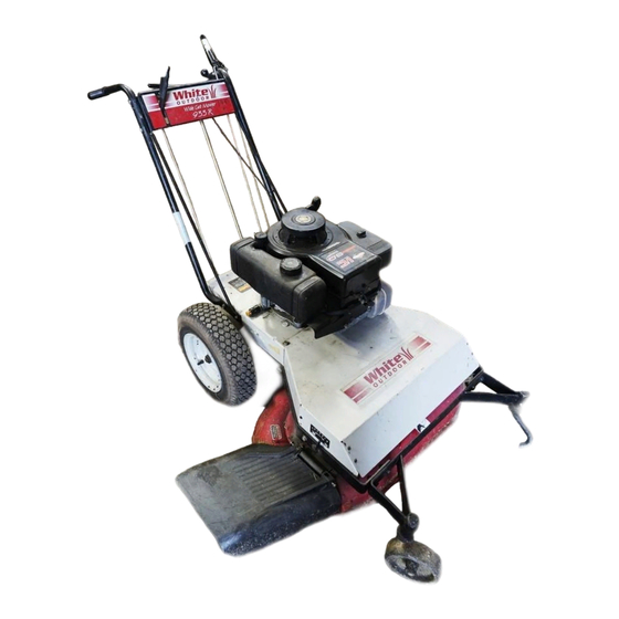
Operator's Manual
WIDE CUT MOWER
Model Series
933R
(12A-751-190)
933E
(12AE751-190)
(Model 933R Shown)
IMPORTANT: READ SAFETY RULES AND INSTRUCTIONS CAREFULLY
Warning: This unit is equipped with an internal combustion engine and should not be used on or near any unimproved forest-
covered, brush-covered or grass-covered land unless the engine's exhaust system is equipped with a spark arrester meeting
applicable local or state laws (if any). If a spark arrester is used, it should be maintained in effective working order by the operator.
In the State of California the above is required by law (Section 4442 of the California Public Resources Code). Other states may
have similar laws. Federal laws apply on federal lands. A spark arrester muffler is available through your nearest engine autho-
rized service dealer or contact the service department, P.O. Box 368022 Cleveland, Ohio 44136-9722.
WHITE OUTDOOR PRODUCTS COMPANY P.O. BOX 361131 CLEVELAND, OHIO 44136-9722
PRINTED IN U.S.A.
FORM NO. 770-1180B
(1905434) 10/99
Advertisement
Table of Contents

Related Manuals for White Outdoor 933E


Summary of Contents for White Outdoor 933E
- Page 1 Federal laws apply on federal lands. A spark arrester muffler is available through your nearest engine autho- rized service dealer or contact the service department, P.O. Box 368022 Cleveland, Ohio 44136-9722. WHITE OUTDOOR PRODUCTS COMPANY P.O. BOX 361131 CLEVELAND, OHIO 44136-9722 PRINTED IN U.S.A.
-
Page 2: Table Of Contents
Dear Owner: Thank you for purchasing this Wide Cut Mower. You now own one of the finest walk-behind mulching/side dis- charge mowers available. Your new mower allows you to mow much faster than the usual walk-behind mower because of its wide 33" cut. Differential steering makes turning easy, while four for- ward speeds and one reverse speed allow precise mowing control. -
Page 3: Section 1: Safety
Section Safety SPARK ARRESTER WARNING TO RESIDENTS OF CALIFORNIA AND SEVERAL OTHER STATES Under California law, and under the laws of several other states, you are not permitted to operate an internal combustion engine using hydrocarbon fuels on any forest covered, brush covered, or grass covered land, or on land covered with grain, hay, or other flammable agricultural crop, without an engine spark arrester in continuous effective working order. -
Page 4: Ii. Slope Operation
Operator Presence Control Bar is released, the system is not working properly. Immediately contact your local White Outdoor Dealer for instructions. Do not use the mower until the mechanism is repaired. -
Page 5: Decals
10. Mower blades are sharp and can cut. Wrap the blade or wear gloves, and use extra caution when servicing them. 11. Do not change the engine governor setting or overspeed the engine. 12. Do not touch engine parts which may be hot from operation. -
Page 6: Section 2: Assembly
INSPECTION AFTER DELIVERY When unpacking the machine, inspect for shipping damage or missing parts. If you find any damage, or if parts are missing, notify the White Outdoor Dealer who sold you the machine. TOOLS/MATERIALS NEEDED: • Wire Cutter • 7/16” Wrench •... - Page 7 (Parts are shown at actual size unless noted otherwise) Cotter Pin, 3/32" x 5/8" Flat Washer, 5/16" Qty: 4 Hex Flange Lock Nut, 1/4-20" Qty: 2 Qty: 1 (Recoil Start Model) Qty: 3 (Electric Start Model) Oil Drain Tube (shown reduced size) Qty. 1 ( for changing oil - see Maintenance Section ) Battery Charger Qty: 1 (shown reduced size)
- Page 8 Section 2: Assembly Black (Ground Lead) Black (Ground Lead) (Positive Lead) (Positive Lead) Figure 2-3: Connect wire terminals to battery terminals. Figure 2-4: Attach wire harness with J- clips. WARNING Charge battery only with charger sup- plied with machine. Do not short circuit battery wires.
- Page 9 Figure 2-6A: Attach wheel drive control rod to lever. B. Attach Operator Presence Control 1. Locate control rod (E, Figures. 2-6 and 2-7) attached at upper end to Operator Presence Control lever (W, Figure 2-7). 2. At bottom of control rod, insert swivel block (G, Figures 2-6 &...
- Page 10 Section 2: Assembly 5. Hold lower part of gear select lever (I, Figure 2-9) against bracket (M). Position retaining plate (N) from parts bag in place as shown in Figure 2-9 (plate below bracket). Secure plate with two 1/4"-20 x 1/2" screws (O) and 1/4”-20 locknuts.
-
Page 11: Section 3: Features And Controls
Section Features and Controls WARNING Before operating mower, be sure to read all safety, controls and operating instructions in this Manual and on decals located on machine. Severe personal injury or property damage could result if this instruction is not followed. IMPORTANT: MOWER EQUIPPED WITH A BLADE-BRAKE-... -
Page 12: Operating Symbols
Section 3: Features and Controls Operating Symbols Various symbols are used on the mower to indicate control settings (your model may not have all of the symbols). These symbols are shown below with a description of their meaning. FAST SLOW CHOKE Gear Select Lever Use this lever (C, Figure 3-1) to select... -
Page 13: Engine Throttle Control
Engine Throttle Control This lever (G, Figure 3-6) is used to adjust engine speeds and to stop the en- gine. Always run engine at fast speed setting for best mower performance. The throttle settings are shown below. CHOKE - Use when starting a cold engine. -
Page 14: Section 4: Operation
Section Operation WARNING Before operating mower, be sure to read all safety, controls and operating instructions in this Manual and on decals located on machine. Severe personal injury or property damage could result if this instruction is not followed. BEFORE OPERATING MOWER 1. -
Page 15: Test Blade Brake-Clutch System
3. Test Blade-Brake-Clutch Control System The mower is equipped with a blade- brake-clutch which is designed to stop the mower blades within three (3) seconds after release of the Operator Presence Control or the Blade Drive Control. Never tamper with, or attempt to defeat the purpose of this safety device. -
Page 16: Engaging The Blades
Section 4: Operation 4. To start engine using recoil starter: A. Stand on left side (as viewed from be- hind handlebars) of machine. Be sure your feet are safely away from the underside of the mower deck and all mower controls are released. Place one foot on top of tire. -
Page 17: Making Turns
C. Put the Gear Select Lever (C, Figure 4- 2) in R (reverse) setting by first mov- ing lever to N (neutral). Then pull lever up, turn it to R position, and re- lease lever. D. To start the wheels, slowly squeeze Wheel Drive Control (D, Figure 4-2). -
Page 18: Blade Brake Control Test
Section 4: Operation first, and then mow the bottom. When mowing ditches, watch out for cans, bottles, or other debris. BLADE BRAKE CONTROL TEST When the Operator Presence Control is released during operation of the mower, the engine does not stop, but the blades should stop within three (3) sec- onds. -
Page 19: Section 5: Maintenance
Section Maintenance Carefully read this Section on mower and engine maintenance and service. Performing the required maintenance ac- cording to schedule will ensure the proper performance and long life of your machine. WARNING Before inspecting, cleaning or servicing the machine, shut off engine, make sure that all moving parts have come to a complete stop, disconnect spark plug wire and move wire away from spark... -
Page 20: Engine Cleaning
Section 5: Maintenance WARNING Before inspecting, cleaning or servicing the unit, shut off engine, wait for all parts to come to a complete stop, disconnect spark plug wire and move wire away from spark plug. Remove ignition key on electric start models. Failure to follow these instructions can result in serious personal injury or property damage. -
Page 21: Engine Storage
WARNING Before inspecting, cleaning or servicing the unit, shut off engine, wait for all parts to come to a complete stop, disconnect spark plug wire and move wire away from spark plug. Remove ignition key on electric start models. Failure to follow these instructions can result in serious personal injury or property damage. -
Page 22: Blade Drive Belt Replacement
Section 5: Maintenance WARNING Before inspecting, cleaning or servicing the unit, shut off engine, wait for all parts to come to a complete stop, disconnect spark plug wire and move wire away from spark plug. Remove ignition key on electric start models. Failure to follow these instructions can result in serious personal injury or property damage. -
Page 23: Blade Brake Replacement
WARNING Before inspecting, cleaning or servicing the unit, shut off engine, wait for all parts to come to a complete stop, disconnect spark plug wire and move wire away from spark plug. Remove ignition key on electric start models. Failure to follow these instructions can result in serious personal injury or property damage. -
Page 24: Wheel Drive Belt Replacement
Section 5: Maintenance WARNING Before inspecting, cleaning or servicing the unit, shut off engine, wait for all parts to come to a complete stop, disconnect spark plug wire and move wire away from spark plug. Remove ignition key on electric start models. Failure to follow these instructions can result in serious personal injury or property damage. -
Page 25: Transmission Neutral Adjustment
WARNING Before inspecting, cleaning or servicing the unit, shut off engine, wait for all parts to come to a complete stop, disconnect spark plug wire and move wire away from spark plug. Remove ignition key on electric start models. Failure to follow these instructions can result in serious personal injury or property damage. -
Page 26: Mower Blades
Section 5: Maintenance WARNING Before inspecting, cleaning or servicing the unit, shut off engine, wait for all parts to come to a complete stop, disconnect spark plug wire and move wire away from spark plug. Remove ignition key on electric start models. Failure to follow these instructions can result in serious personal injury or property damage. -
Page 27: Cleaning Underside Of Mower Deck
WARNING Before inspecting, cleaning or servicing the unit, shut off engine, wait for all parts to come to a complete stop, disconnect spark plug wire and move wire away from spark plug. Remove ignition key on electric start models. Failure to follow these instructions can result in serious personal injury or property damage. -
Page 28: Lubrication Chart
Section 5: Maintenance WARNING Before inspecting, cleaning or servicing the unit, shut off engine, wait for all parts to come to a complete stop, disconnect spark plug wire and move wire away from spark plug. Remove ignition key on electric start models. Failure to follow these instructions can result in serious personal injury or property damage. -
Page 29: Maintenance Chart
ATTENTION! This chart describes service guidelines only. It does not provide complete service information. Complete service is available from your local White Outdoor Dealer. Before performing any of the maintenance procedures, refer to the appropri- ate information contained in this Manual or the Engine Owner’s Manual for the correct safety precautions and maintenance procedures. -
Page 30: Troubleshooting Chart
ATTENTION! This table describes service guidelines only. It does not provide com- plete service information. Complete service is available from your local White Outdoor Dealer. Before performing any of the cor- rections in this table, refer to the appropri- ate information contained in this Manual or the Engine Owner’s Manual for the correct... - Page 31 NOTES...
- Page 32 5. The provisions as set forth in this warranty provide the sole and exclusive remedy of White Outdoor Products Company’s obligations arising from the sales of its products. White Outdoor Products Company will not be liable for incidental or consequential loss or damage.