Table of Contents
Advertisement
Quick Links
OPERATOR'S MANUAL
Model
Z - 165
IMPORTANT: READ SAFETY RULES AND INSTRUCTIONS CAREFULLY
Warning:
This unit is equipped with an internal combustion engine and should not be used on or near any unimproved forest-
covered, brush-covered or grass-covered land unless the engine's exhaust system is equipped with a spark arrester meeting
applicable local or state laws (if any). If a spark arrester is used, it should be maintained in effective working order by the operator.
In the State of California the above is required by law (Section 4442 of the California Public Resources Code). Other states may have
similar laws. Federal laws apply on federal lands. A spark arrester for the muffler is available through your nearest engine authorized
service dealer or contact the service department, P.O. Box 361131 Cleveland, Ohio 44136-9722.
WHITE OUTDOOR PRODUCTS COMPANY P.O. BOX 361131 CLEVELAND, OHIO 44136-9722
PRINTED IN U.S.A.
FORM NO. 770-10102A
(5/99)
Advertisement
Table of Contents

Related Manuals for White Outdoor Z - 165


Summary of Contents for White Outdoor Z - 165
- Page 1 Federal laws apply on federal lands. A spark arrester for the muffler is available through your nearest engine authorized service dealer or contact the service department, P.O. Box 361131 Cleveland, Ohio 44136-9722. WHITE OUTDOOR PRODUCTS COMPANY P.O. BOX 361131 CLEVELAND, OHIO 44136-9722 PRINTED IN U.S.A.
-
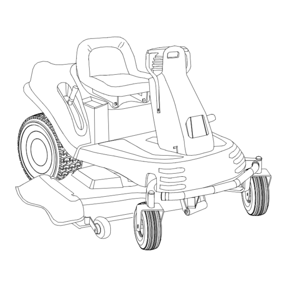
Page 2: Section 1: Finding Your Model Number
• Every mower has a model plate. You can locate it by looking down at the battery stand. It is located on the rear face of the battery stand. Copy the model number here: WHITE OUTDOOR PRODUCTS COMPANY P.O. BOX 361131... -
Page 3: Section 3: Important Safe Operation Practices
SECTION 3: IMPORTANT SAFE OPERATION PRACTICES WARNING: THIS SYMBOL POINTS OUT IMPORTANT SAFETY INSTRUCTIONS WHICH, IF NOT FOLLOWED, COULD ENDANGER THE PERSONAL SAFETY AND/OR PROPERTY OF YOURSELF AND OTHERS. READ AND FOLLOW ALL INSTRUCTIONS IN THIS MANUAL BEFORE ATTEMPTING TO OPERATE YOUR LAWN MOWER. FAILURE TO COMPLY WITH THESE INSTRUCTIONS MAY RESULT IN PERSONAL INJURY. -
Page 4: Slope Operation
to mow through unusually tall, dry grass (e.g., pas- ture) or piles of dry leaves. Debris may build up on the mower deck or contact the engine exhaust pre- senting a potential fire hazard. 2. SLOPE OPERATION Slopes are a major factor related to loss of control and tip- over accidents which can result in severe injury or death. - Page 5 • After striking a foreign object, stop the engine, remove the wire from the spark plug and thoroughly inspect the mower for any damage. Repair the dam- age before restarting and operating the mower. • Grass catcher components are subject to wear, dam- age and deterioration, which could expose moving parts or allow objects to be thrown.
- Page 6 USE THIS PAGE AS A GUIDE TO DETERMINE SLOPES WHERE YOU MAY NOT OPERATE SAFELY. Do not mow on inclines with a slope in excess of 15 degrees (a rise of approximately 2-1/2 feet every 10 feet). A riding mower could overturn and cause serious injury.
-
Page 7: Section 4: Controls
SECTION 4: CONTROLS PTO Switch Ignition/Light Switch Hour/RPM Meter HOUR/RPM METER (If Equipped) The hour/RPM meter is an LCD (liquid crystal display) display that is located on the right control panel. The meter’s display stays on continuously. (See Figure 3) •... -
Page 8: Lift Handle
LIFT HANDLE Height Positions 1 through 7 and L (lock) The lift handle is located on the right fender. It raises and lowers the cutting height of the mower deck used by the Z-series. (See Figure 3) & (See Figure 5) •... -
Page 9: Power Take-Off (Pto) Switch
POWER TAKE-OFF (PTO) SWITCH Top View The PTO switch is located on the right control panel. It controls the engagement of the cutting blades. (See Figure 7) When the switch is: • UP: The cutting blades are engaged (blades are turning). •... - Page 10 DRIVE HANDLES The drive handles (left and right) are located at the top of the control tower. (See Figure 8) The drive handles are used to move, steer, and stop the Z-series. The drive handles will return toward the neutral position when released;...
-
Page 11: Indicator Panel
INDICATOR PANEL Low Engine Oil The indicator panel is located at the top of the control tower. There are two indicator lights on the panel. (See Figure 10). When the corresponding light is illuminated it indicates: • LOW ENGINE OIL: Stop the tractor immediately and check the engine oil level. Continuing to operate with low engine oil can severely damage the engine. -
Page 12: Section 5: Operation
SECTION 5: OPERATION BEFORE OPERATING 1. Study this manual carefully. It has been provided to help you safely operate and maintain this unit. 2. Familiarize yourself with all instruments and controls. 3. Fill the fuel tank according to the MAINTENTANCE section. 4. -
Page 13: Starting A Flooded Engine
1. Sit in the seat of the tractor facing forward with your feet straddling the control tower. 2. Push the choke lever to the full choke position (all the way toward the front of the tractor). 3. Push the throttle lever to the fast (rabbit) position (all the way toward the front of the tractor). Note: Less choking may be required due to engine temperature variance. -
Page 14: Quick Reference Chart
QUICK REFERENCE CHART The Z-series can turn with a zero radius. The Z-series uses the rear tires to turn. When turning with a zero radius, the rear tires are used as the pivot point. A conventional tractor can make a circle but it needs a turning radius, usually based on the distance between the front and rear wheels. - Page 15 MOWING For best results, consider the following recommendations: • Mow the first two laps with the discharge pointing toward the center. • Mow the next two laps with the discharge pointing outside (away from center) for a balanced cut and improved appearance.
-
Page 16: Section 6: Adjustments
WARNING: The hydraulic relief levers are near engine parts that can be HOT. To avoid injury, wait until engine parts have cooled before disengaging. 1. Position the Z-series on a flat and level surface. 2. Engage the parking brake. 3. Remove the hydraulic relief levers from the lock position. There is a lever for the right and left hydraulic pump. 4. -
Page 17: Adjusting Brake Force
ADJUSTING BRAKE FORCE Frame Measure Gap 1. Place the Z-series on level surface without the brake engaged and place blocks behind the wheels. 2. Turn the engine OFF and remove the key from the ignition. 3. From underneath the Z-series directly behind the caster wheel pivot bar, locate the brake rods. There are two, one on the right and one on the left. - Page 18 7. Pull up on the control tower cover and slide up and over the control tower. 8. Remove both safety switches from their respective holders by squeezing together on the retaining clips while gently pushing upward until the switches clear the brackets. 9.
-
Page 19: Section 7: Lubrication
16. Remove quarter inch by seven inch pins from top and bottom holes. 17. Set parking brake and start the engine (set throttle at full speed). Make sure that the PTO is off. 18. Rotate rods (lengthen or shorten) to bring each hydrostat to neutral. NOTE: The control linkage going to the hydrostatic pump has left-hand threads at the pump and right-hand threads at the tower. - Page 20 GREASE POINT LOCATIONS Control Tower Grease Fittings Deck Lift Pivot Grease Fittings Lift Handle Grease Fitting Pivot Bar Grease Fitting Caster Wheel Grease Fitting 42” Mower Deck Grease Fittings Caster Wheel Spindle Grease Fitting...
-
Page 21: Section 8: Maintenance
SECTION 8: MAINTENANCE ENGINE COMPARTMENT The engine is located behind the operator seat. FUEL TANK The fuel tank filler cap is located on the left-rear fender panel. Take the fuel cap off by unscrewing. Fill the gas tank from this point. The fuel tank has approximately a 4.0 gallon capacity. WARNING: Never fill the fuel tank indoors, with engine running or while engine is hot. -
Page 22: Adding Hydraulic Oil
ADDING HYDRAULIC OIL WARNING: Never overfill the hydraulic units. Damage can result if the oil level is not within the operating range. Note: When adding hydraulic oil, do so in small quantities and recheck the oil level before adding more. It is important that you do not over fill the reservoir. -
Page 23: Changing The Fuse
REPLACING THE HEAD LAMP BULB 1. Remove the ignition key from ignition switch. 2. Detach the bottom of the rubber boot cover on the drive handles. 3. Slide the boot cover all the way up (toward the drive handles) to access the drive handle bolts. 4. -
Page 24: Removing The Battery
Warning: When removing the cables from the battery follow order of the steps to avoid a short between the wrench and the frame. REMOVING THE BATTERY 1. Remove the negative (black) cable. 2. Remove the positive (red) cable. 3. Unscrew the two wing nuts from the battery rods. 4. -
Page 25: Section 9: Mower Decks
SECTION 9: MOWER DECKS The mower deck must be level horizontally (side-to-side and front-to-back) for even cutting. CHECKING THE LEVEL OF THE MOWER DECK - Side to Side - Front to Back Measurement 1. Check the rear tires pressure for proper inflation and tracking. 2. - Page 26 J Pin Bracket 3. Remove the left belt cover by removing the wing nut. 4. Release the belt tension spring by releasing the belt tension bar. 5. Remove the belt from clutch below the engine in the rear of the unit. 6.
-
Page 27: Removing The Mower Deck
2. Turn the threaded link the appropriate distance down. • Every 1/2 turn =1/32” (.03125”) • Example: If the front measurement is 4.625” the threaded link should be turned 2 full turns (1/8” or 0.125”) down. 3. Reconnect the hanger links to the hanger brackets and the retaining arms to the tractor. 4. - Page 28 J Pin Bracket 12. Turn the pulley counterclockwise until the belt is completely off of the pulley. 13. Locate the clutch pulley. It is located in the rear of the tractor, below the muffler. (See Figure 25) 14. Remove the belt from the clutch pulley. WARNING: Exhaust and surrounding engine parts are very hot and can cause severe burns when touched.
-
Page 29: Installing The Mower Deck
17. Move the mower deck toward the rear of the tractor until the retaining arms clear the mower deck. 18. From the right side, pull the mower deck out from under the tractor. INSTALLING A NEW MOWER DECK DRIVE BELT 1. -
Page 30: Removing A Blade
J Pin Bracket 10. Repeat Step 7 and Step 8 for the other side of the mower deck. 11. From the rear, attach the belt around the clutch pulley. 12. Engage tension arm by moving it into the bracket to maintain belt tension. 13. -
Page 31: Removing The Drive Belt
2. Use a 1-1/8 inch socket wrench on the pulley side of the spindle to secure. 3. Tighten the nut to 100 ft-lbs (136 Nm). LUBRICATION OF MOWER DECK Lubricate the mower deck and its parts as required. • Each spindle has a grease fitting and all pivot points should be lubricated with motor oil. REMOVING THE DRIVE BELT Visually inspect the drive belt for wear and cracking. -
Page 32: Section 11: Trouble Shooting Guide
WARNING: Drain fuel into an approved container, in open air, and away from open flames. 5. Clean the engine and the entire Z-series thoroughly. 6. Lubricate all lubrication points. 7. Follow the battery storage guidelines (refer to BATTERY STORAGE for details). 8. - Page 38 Log splitter pumps, valves and cylinders have a sepa- rate one year warranty. d. White Outdoor Co. does not extend any warranty for products sold or exported outside of the United States of America, its possessions and territories, except those sold through White Outdoor Co.