Emerson Daniel 3410 Series Installation Manual
Gas ultrasonic flow meters
Hide thumbs
Also See for Daniel 3410 Series:
- Operation manual (192 pages) ,
- Installation manual (112 pages) ,
- Instructions for use, maintenance and installation manual (110 pages)
Table of Contents
Advertisement
Quick Links
Download this manual
See also:
Operating Manual
Advertisement
Table of Contents

Related Manuals for Emerson Daniel 3410 Series


Summary of Contents for Emerson Daniel 3410 Series
- Page 1 Installation manual P/N 3-9000-789, Rev C April 2018 ™ Daniel 3410 Series Gas Ultrasonic Flow Meters Models 3415, 3416 and 3417...
- Page 2 +44 (0)1786.433400 +44 (0)1786.433401 Middle East Africa (Dubai, UAE) +971 4 8118100 +971 4 8865465 Daniel Measurement and Control, Inc. (Headquarters) 11100 Brittmoore Park Drive Houston, TX 77041 USA http://www.emerson.com Email • Customer Service: Daniel.SystemSales@Emerson.com • Customer Support: Daniel.SystemSales@Emerson.com •...
- Page 3 Signal words and symbols Pay special attention to the following signal words, safety alert symbols and statements: Safety alert symbol This is a safety alert symbol. It is used to alert you to potential physical injury hazards. Obey all safety messages that follow this symbol to avoid possible injury or death.
- Page 4 Verify that this is the correct instruction manual for your Daniel product. If this is not the correct documentation, contact Daniel at 1-713-827-6314. You may also download the correct manual from: https://www.emerson.com/en-us/catalog/supervisory-control-systems. • Save this instruction manual for future reference.
- Page 5 Product operation (Personnel): • To prevent personal injury, personnel must follow all instructions of this manual prior to and during operation of the product. • Follow all warnings, cautions, and notices marked on, and supplied with, this product. • System should be designed to avoid over pressure conditions or exceeding maximum safe flow rate if meter losses measurement.
- Page 6 Notice THE CONTENTS OF THIS PUBLICATION ARE PRESENTED FOR INFORMATIONAL PURPOSES ONLY, AND WHILE EVERY EFFORT HAS BEEN MADE TO ENSURE THEIR ACCURACY, THEY ARE NOT TO BE CONSTRUED AS WARRANTIES OR GUARANTEES, EXPRESSED OR IMPLIED, REGARDING THE PRODUCTS OR SERVICES DESCRIBED HEREIN OR THEIR USE OR APPLICABILITY. ALL SALES ARE GOVERNED BY DANIEL'S TERMS AND CONDITIONS, WHICH ARE AVAILABLE UPON REQUEST.
- Page 7 Warranty and Limitations 1. LIMITED WARRANTY: Subject to the limitations contained in Section 2 herein, Daniel Measurement & Control, Inc. (“Daniel”) warrants that the licensed firmware embodied in the Goods will execute the programming instructions provided by Daniel, and that the Goods manufactured by Daniel will be free from defects in materials or workmanship under normal use and care and Services will be performed by trained personnel using proper equipment and instrumentation for the particular Service provided.
-
Page 9: Table Of Contents
Daniel MeterLink software ......................5 Daniel 3410 series meter design ....................7 Meter specifications ........................11 Pre-installation considerations ....................19 Safety ............................20 1.10 Daniel 3410 series certifications and approvals ................21 1.11 FCC compliance ......................... 21 1.12 References ..........................22 Chapter 2 Mechanical installation .................... - Page 10 Contents Using a Field Communicator to configure the meter ..............109 Security seals for the meter ......................110 Appendices and reference Appendix A Engineering drawings ....................111 3410 Series engineering drawings ................... 111 Appendix B Open source licenses ....................113 List of source codes for executable files ..................113 B.1.1 GNU General Public License ..................115 B.1.2...
-
Page 11: Chapter 1 Introduction
P/N 3-9000-761 HART Field Device Specification Manual • P/N 3-9000-769 Daniel 3410 Series Ultrasonic Gas Flow Meter Maintenance and Troubleshooting Manual Daniel 3415 Gas Ultrasonic Flow meter is a 4-path chordal design combined with a single- path bounce design. This technology provides custody transfer gas measurement combined with integrated check metering. -
Page 12: Typical Applications
Introduction Typical applications Daniel Dual-Configuration 3410 Series Ultrasonic Gas Flow Meters have various configurations that meet a broad range of customer requirements. Each meter comes fully assembled from Daniel. The technology can be applied to custody transfer, allocation measurement, and check metering applications such as: •... -
Page 13: Acronyms, Abbreviations And Definitions
Ethernet access • On-board LES status indicators • Analog pressure and temperature inputs ™ • Communication via Emerson's AMS Device Manager and Field Communicator • API Chapter 21 compliant event and data logging (gas meters) ™ ® • Daniel MeterLink... - Page 14 Introduction Acronym or abbreviation Definition DHCP Dynamic Host Configuration Protocol decimeter (10 -1 meters, length unit) Error Correction Code EEPROM Electrically-Erasable, Programmable Read-Only Memory Flash non-volatile, programmable read-only memory FODO output that is userconfigurableaseither a FrequencyorDi- gitalOutput ® HART Communication Protocol Highway Addressable Remote Transducer communica- tions protocol hour (time unit)
-
Page 15: Daniel Meterlink Software
Introduction Acronym or abbreviation Definition pounds per square inch (pressure unit) psia pounds per square inch absolute (pressure unit) psig pounds per square inch gage (pressure unit) Radius of meter radian (angle) Random Access Memory Request-to-Send; the RS-232C handshakingsignaloutput- by a receiverwhen it is readytoreceivedata RTU MODBUS A Modbusprotocolframingformat in whichelapsedtime- betweenreceivedcharac-ters is used to separate messag-... - Page 16 Refer to the Daniel MeterLink Software for Gas and Liquid Ultrasonic Meters Quick Start Manual (P/N 3-9000-763) for installation instructions and setup for initial ™ communications. You may download the manual from the Daniel MeterLink page: http://www.emerson.com/en-us/automation/daniel Gas Ultrasonic Flow Meter...
-
Page 17: Daniel 3410 Series Meter Design
Introduction Daniel 3410 series meter design Daniel 3410 Series Gas Ultrasonic Flow Meters are designed to accurately measure products in applications where reliable performance is critical, by measuring the difference in signal transit time with and against the flow across one or more measurement path(s). A signal transmitted in the flow direction travels faster than one transmitted against the flow direction. - Page 18 Introduction utilizes a single-path for the check measurement and an additional diagnostic path designed to provide information about the bottom of the pipe. The single check measurement path is positioned at 30 degrees off vertical while the diagnostic path is vertical.
- Page 19 Introduction Model 3415/3416/3417 Dual Configuration Gas Ultrasonic Meter co-located meter heads can be configured to share flow data to improve meter diagnostics. Data sharing can be setup via Ethernet between the two co-located transmitter heads. Meters will share measurement data and provide comparison for SOS and Meter flow velocity. Figure 1-4: Dual configuration meter data sharing connections with Expansion I/O Module...
- Page 20 Introduction Daniel Model 3415/16/17 Dual Configuration Meters can be connected to customer infrastructure through separate Ethernet connections to each head. Expansion I/O Module is not required for data sharing. Data sharing connection will occur through the external user network connection. Note Model 3415 does not have the vertical bounce path (see Daniel 3415 description) Figure 1-6:...
-
Page 21: Meter Specifications
Introduction Meter specifications WARNING! CONTENTS MAY BE UNDER PRESSURE When the meter is under pressure, DO NOT attempt to remove or adjust the transducer holder. Attempting to do so may release pressurized gases, resulting in serious injury or equipment damage. WARNING! CONTENTS MAY BE HAZARDOUS The meter must be fully depressurized and drained before attempting to remove the... - Page 22 Introduction Table 1-1: Daniel models 3415, 3416 and 3417 meter specifications Daniel 3415, 3416 and 3417 meter specifications Meter type Number of paths • 3415: 4-path chordal design combined with a single- path bounce design • 3416: 4-path chordal design combined with a two-path bounce design •...
- Page 23 Introduction Table 1-1: Daniel models 3415, 3416 and 3417 meter specifications (continued) Daniel 3415, 3416 and 3417 meter specifications Linearity Model 3415 4-path chordal design combined with a single- path bounce design • 4-path chordal design Flow calibrated accuracy is ± 0.1% of reading over the entire flow calibration range Without flow calibration, accuracy is typically ±...
- Page 24 Introduction Table 1-1: Daniel models 3415, 3416 and 3417 meter specifications (continued) Daniel 3415, 3416 and 3417 meter specifications Velocity range • 100 ft/s (30m/s) with over-range) • 125 fps (38 m/s) on some line sizes • Meter meets or exceeds AGA9 (2007) performance specifications Table 1-2: Performance specifications...
- Page 25 Introduction Table 1-1: Daniel models 3415, 3416 and 3417 meter specifications Daniel 3415, 3416 and 3417 meter specifications Model 3417 AGA 9 / ISO 17089 Flow rate values (US Customary Units) Meter size (IN) 8 to 24 (ft/ (ft/s) CF * (ft/ CF * (*) CF = consult factory...
- Page 26 Introduction Table 1-1: Daniel models 3415, 3416 and 3417 meter specifications (continued) Daniel 3415, 3416 and 3417 meter specifications Power Meter • 10.4 VDC to 36 VDC • 11 W power consumption (15 W maximum) Serial cable • Belden #9940 or equivalent (22 gauge) Capacitance (pF/m) 121.397 (conductor to conduc- tor) Capacitance (pF/m) 219.827 (conductor to other...
- Page 27 Introduction Table 1-1: Daniel models 3415, 3416 and 3417 meter specifications (continued) Daniel 3415, 3416 and 3417 meter specifications Note The process temperature must not exceed the operating temperature range of the transducers. Note T-21 and T-41 transducers are used for the direct paths of 16" and larger meters and the reflective paths of all sized meters.
- Page 28 Introduction Table 1-1: Daniel models 3415, 3416 and 3417 meter specifications (continued) Daniel 3415, 3416 and 3417 meter specifications Analog Input(s) (2) 4-20 mA • AI-1 Temperature • AI-2 Pressure Note The analog-to-digital conversion accuracy is within ±0.05% of full scale over the operating temperature range. Note AI-1 and AI-2 are electronically isolated and operate in sink ®...
-
Page 29: Pre-Installation Considerations
Introduction Table 1-1: Daniel models 3415, 3416 and 3417 meter specifications (continued) Daniel 3415, 3416 and 3417 meter specifications Channel B Phase options: • Lag forward, Lead reverse (Phase B lags Phase A while re- porting forward flow, leads Phase A while reporting reverse flow) •... -
Page 30: Safety
• Data collection and retention procedures Safety The Daniel 3410 Series Gas Ultrasonic Flow Meter is suitable for use in U.L. Class 1, Division 1, Group C and D hazardous locations. NOTICE An “X” signifies the user should contact Daniel Measurement and Control, Inc. for information on the dimensions of the flameproof joints. -
Page 31: Daniel 3410 Series Certifications And Approvals
Refer to the nameplate tag on the meter body, the wiring diagram (P/N DMC-005324) in Appendix A and observe all safety precautions. Daniel 3410 Series Gas Ultrasonic Flow Meters operate within the pressure and temperature range of the device (also see Section 1.6 for meter specifications). -
Page 32: References
Introduction NOTICE Changes or modifications not expressly approved by the party responsible for compliance could void the user's authority to operate the equipment. 1.12 References Gould Modbus Protocol Reference Guide, Rev. B, PI-MBUS-300 Measurement of Fuel Gas By Turbine Meters, American Gas Association, Transmission Measurement Committee Report No. -
Page 33: Chapter 2 Mechanical Installation
Mechanical installation Mechanical installation Topics covered in this chapter: • Meter piping, lifting and mounting • Meter components • Piping recommendations • Pre-installation inspection • Mounting requirements in heated or cooled pipelines Meter piping, lifting and mounting Refer to the following sections for piping recommendations, lifting with hoist rings and slings, mounting in heated or cooled pipelines and safety warnings and precautions. - Page 34 Mechanical installation CAUTION! TRIPPING HAZARD Clear all obstacles or obstructions from the work area when transporting, installing or removing the meter. Failure to clear the work area may cause injury to personnel. WARNING! CRUSHING HAZARD Do not remove flange stabilizers. Attempting to do so may allow the meter to roll, resulting in serious injury or equipment damage.
-
Page 35: Meter Components
Mechanical installation Meter components Daniel 3410 Series Gas Ultrasonic Flow Meters are assembled, configured and tested at the factory. The meter components include the transmitter electronics enclosure, the base electronics enclosure and the meter body with transducer assemblies. WARNING! CONTENTS MAY BE UNDER PRESSURE When the meter is under pressure, DO NOT attempt to remove or adjust the transducer holder. - Page 36 Mechanical installation WARNING! CONTENTS MAY BE HAZARDOUS The meter must be fully depressurized and drained before attempting to remove the transducer holder. If gas or fluid begins to leak from the transducer holder, stop immediately and reinstall the holder. Failure to comply may cause serious injury or equipment damage. A.
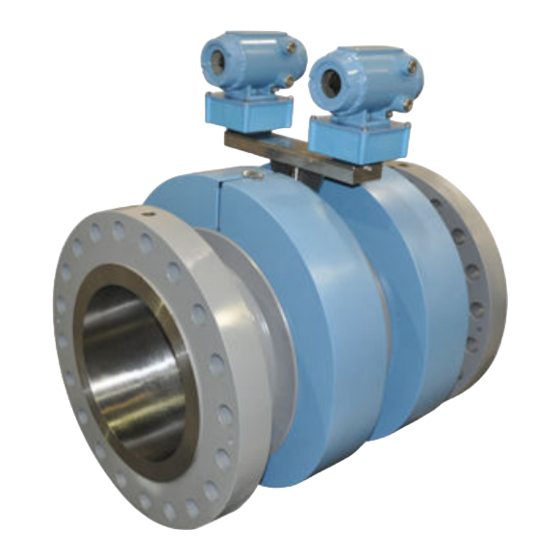
- Page 37 Mechanical installation The 3417 dual 4-path ultrasonic meter components are shown below. Figure 2-1: Daniel 3417 Flow Meter assembly A. Explosion-proof transmitter enclosure (CPU Module, Power Supply, I.S. Barrier Board Backplane board) (Optional: glass endcap for Local Display) B. Intrinsically-safe base enclosure includes Acquisition Module C.
- Page 38 Mechanical installation The 3416 and the 3415 dual ultrasonic meter components are shown below. Figure 2-2: Daniel 3415 and 3416 Flow Meter assembly A. Explosion-proof transmitter enclosure (CPU Module, Power Supply, I.S. Barrier Board Backplane board) (Optional: glass endcap for Local Display) B.
- Page 39 Mechanical installation Figure 2-3: Transmitter electronics enclosure with optional local display and glass endcap A. Transmitter electronics enclosure with glass endcap B. Local display Installation manual...
-
Page 40: Piping Recommendations
Mechanical installation Piping recommendations WARNING! BURST HAZARD Before pipeline cleaning and maintenance ("pigging operations"), remove straightening vanes or flow conditioners. Failure to comply may cause excessive pressure in the meter system, resulting in death, serious injury or equipment damage. Figure 2-4: 3410 Series Gas Ultrasonic Flow Meter with flow conditioner for uni- directional flow Figure 2-5:... - Page 41 Mechanical installation NOTICE For optimal flow measurement conditions, Daniel suggests the piping configurations below. Regardless of the configuration selected, the user agrees to accept full responsibility for the site piping design and installation. Flow conditioning is recommended for best measurement results •...
- Page 42 The meter is provided with dowel pins to align the meter body bore with the bore of the mating piping. • Daniel 3410 Series Ultrasonic Gas Flow Meters should be mounted in horizontal piping with the chord paths horizontal. Gas Ultrasonic Flow Meter...
-
Page 43: Pre-Installation Inspection
Mechanical installation CAUTION! FAULTY METER INSTALLATION Correctly install the equipment. If meter bodies are mounted or oriented differently than specified above, debris or gas may collect in the transducer ports which could adversely affect the transducer signals, or cause equipment damage. •... - Page 44 Mechanical installation WARNING! DANGER TO PERSONNEL AND EQUIPMENT Lifting a Daniel Ultrasonic Meter with other equipment The following lifting instructions are for installation and removal of the Daniel Ultrasonic Meter ONLY. The instructions below do not address lifting the Daniel ultrasonic meter while it is attached, bolted, or welded to meter tubes, piping, or other fittings.
- Page 45 Mechanical installation Operators SHALL NOT use Eye Bolts (see ) in the Daniel Ultrasonic Meter flange tapped holes to aid in lifting or maneuvering the unit. Operators SHALL NOT use other Hoist Rings that do not fully seat flush with the counter bore on the top of the meter flanges.
- Page 46 Mechanical installation Figure 2-11: Safety approved hoist ring Figure 2-12: Non-compliant eye bolt Gas Ultrasonic Flow Meter...
- Page 47 Mechanical installation Safety precautions using safety engineered swivel hoist rings Read and follow the Safety Precautions listed below. Meters must only be lifted by personnel properly trained in the safe practices of rigging and lifting. Remove the plug bolts installed in the tapped holes on the top of the flanges. Do not discard the bolts as they must be reinstalled once the lifting operation is complete to prevent corrosion of the tapped holes.
- Page 48 Mechanical installation Figure 2-13: Correct sling attachment for Shell Shroud meters NEVER allow the slings to contact the electronics enclosure. Damage to the enclosure may occur. Use a spreader bar with the slings to prevent contact with the electronics enclosure and the base enclosure (see Figure 2-12). If the slings do come in contact with the electronic enclosure then remove the two bolts holding the enclosure to its base and temporarily remove the head from the meter during the lifting operation.
- Page 49 Mechanical installation Figure 2-14: Incorrect sling attachment NEVER apply shock loads to the meter. Always lift the meter gradually. If shock loading ever occurs, the hoist ring must be inspected per manufacturer's recommendations prior to any further service. If a proper inspection cannot be performed, discard the hoist ring.
- Page 50 Mechanical installation meter. NEVER use the hoist rings on the meter to lift other components such as meter tubes, piping or fittings attached to the meter. Doing so will exceed the load rating of the hoist rings. Remove the hoist rings from the meter after lifting is completed and store them in an appropriate case or container per their manufacturer's recommendation.
- Page 51 The following instructions are intended to provide general guidelines for using proper lifting slings when lifting a Daniel 3410 Series Gas Ultrasonic Flow Meter by itself. These instructions are intended to be followed in addition to your company's standards or the DOE-STD-1090-2004 Hoisting and Rigging standard if such company standards do not exist.
- Page 52 Mechanical installation Figure 2-15: Correct sling attachment Visually inspect the slings prior to use for any signs of abrasion or other damage. Refer to the sling manufacturer's procedures for proper inspection of the particular sling you are using. Only use slings with ratings that exceed the weight to be lifted. Reference your company's standards for safety factors that must be included when calculating the load rating.
- Page 53 Mechanical installation NEVER allow the slings to contact the electronics enclosure or the transducer cabling. Damage to the meter may occur. If the slings do come in contact with the electronics enclosure, then remove the two bolts holding the enclosure to its base and temporarily remove the head from the meter during the lifting operation (Remove the two bolts holding the enclosure to its base and unplug the cable from the Acquisition Module.
-
Page 54: Mounting Requirements In Heated Or Cooled Pipelines
Mechanical installation Mounting requirements in heated or cooled pipelines The ambient operating temperature of the Daniel 3410 Series Gas Ultrasonic Flow Meter electronics (i.e. Flameproof enclosure and Intrinsically safe base enclosure) is -40° C (-40° F) to +60° C (+140° F). -
Page 55: Chapter 3 Electrical Installation
Electrical installation Electrical installation Topics covered in this chapter: • Cable length TTL mode • Cable length Open Collector mode • Grounding meter electronics housing • Conduit seals • Wiring and I/O Security seal installation • Cable length TTL mode The maximum cable length is 2000 feet when the Digital Output “TTL”... -
Page 56: Grounding Meter Electronics Housing
Electrical installation Table 3-1: Configurations for open collector frequency outputs (continued) Pull-up Maxi- Cable Cable re- resist- mum fre- voltage Cable sistance Cable ance Total quency Sink drop 16.8 10.00 516.8 5000 0.046 0.780 33.6 20.00 533.6 5000 0.045 1.511 57.12 34.00 557.12... - Page 57 Electrical installation Figure 3-1: Internal Transmitter Electronics Enclosure chassis ground A. Transmitter Electronics Enclosure ground lug Installation manual...
-
Page 58: Conduit Seals
Electrical installation Figure 3-2: External ground lug A. External ground lug Conduit seals Conduit seals are required for meter installations in hazardous environments. Adhere to safety instructions to protect personnel and equipment. WARNING! EXPLOSION HAZARD To reduce the risk of an explosion or fire, conduit runs must have a sealing fitting connected within 457.2 mm (18 inches) of the enclosure. -
Page 59: Startup For Systems Using Explosion-Proof Conduit
Electrical installation WARNING! EXPLOSION HAZARD Substitution of components may impair the intrinsic safety and cause ignition of flammable or combustible atmospheres. Disconnect power before servicing. Failure to remove power and use Daniel approved components may cause serious injury. 3.4.1 Startup for systems using explosion-proof conduit Assemble conduit to the Transmitter Electronics Enclosure. - Page 60 Electrical installation Figure 3-3: Electronics field wiring - upper terminal block, switches, ground lug - Type 2 CPU Module A. Conduit wiring entry (four entries) c. Analog In • Analog In (AI1) B. Switches: • Analog Input 1 (Temperature) 1. Port A •...
- Page 61 Electrical installation Figure 3-4: Transmitter electronics field wiring lower terminal block - Type 2 CPU Module A. Upper terminal block d. Ethernet • Ethernet (orange and white wire) a. FODO Group 1 connections • Ethernet (orange wire) • FODO1 • Ethernet (green and white wire) •...
- Page 62 Electrical installation Figure 3-5: Electronics field wiring - upper terminal block, switches, ground lug - Type 4CPU Module A. Conduit wiring entry (four entries) b. Analog In • Analog In (AI1) B. Switches: • Analog Input 1 (Temperature) 1. Port A •...
- Page 63 Electrical installation Figure 3-6: Transmitter electronics field wiring lower terminal block - Type 4 CPU Module A. Upper terminal block d. Ethernet • Ethernet (orange and white wire) a. FODO Group 1 connections • Ethernet (orange wire) • FODO1 • Ethernet (green and white wire) •...
-
Page 64: Startup For Systems That Use Flame-Proof Cable
Electrical installation Set or configure the meter operating parameters using Daniel MeterLink. For additional installation information refer to the system wiring diagram (see ), Daniel MeterLink Software for Gas and Liquid Ultrasonic Meters Quick Start Manual (P/N 3-9000-763) and use the Daniel MeterLink Field Setup Wizard to complete the configuration. -
Page 65: Wiring And I/O
Re-apply electrical power to the system. Wiring and I/O Daniel MeterLink uses the TCP/IP protocol to communicate with the Daniel 3410 Series Ultrasonic Gas Flow Meter electronics instead of Modbus ASCII or RTU. The TCP/IP protocol only works across either Ethernet, RS-485 full duplex (4-wire) or RS-232. Daniel MeterLink can communicate with multiple meters if they are multi-dropped using 4-wire, full duplex RS-485 mode. - Page 66 Electrical installation Figure 3-7: CPU Module labeling and LED indicators - Type 2 A. Acquisition/Measurement mode B. Power C. LED 5 - communication between CPU and Acquisition Module D. LED 4 - link between CPU and Acquisition Module E. RX (RS-485/RS-232) - receiving data F.
- Page 67 Electrical installation Figure 3-8: CPU Module labeling and LED indicators - Type 4 A. Acquisition/Measurement mode B. Power C. LED 5 - communication between CPU and Acquisition Module D. LED 4 - link between CPU and Acquisition Module E. RX (RS-485/RS-232) - receiving data F.
- Page 68 Electrical installation Table 3-2: CPU Module labeling and LED functions (continued) CPU Module la- bel or LED Function Switch position indicator or LED DHCP • Dynamic Host Protocol Server - Switch position enables you to communicate with • ON - the meter is enabled to act as a Daniel meter that is not connec- a DHCP server for a single DHCP ted to a network.
- Page 69 NOTICE RESTRICTED ETHERNET AND SERIAL CONNECTIVITY USAGE Failure to restrict Ethernet and communication access to the Daniel 3410 Series Gas Ultrasonic Flow Meter can result in, among other things, unauthorized access, system corruption, and/or data loss. User is responsible for ensuring that physical access and Ethernet or electronic access to the Daniel 3410 Series Gas Ultrasonic Flow Meter is appropriately controlled and any necessary security precautions are implemented;...
- Page 70 Electrical installation Table 3-3: Ethernet cable to PC communication Ethernet communication Wire color White w/Green Stripe Solid Green TX - White w/Orange Stripe Solid Orange RX - Use Ethernet cable, Daniel P/N 1-360-01-596, to connect the PC to the meter. A DIN 41612 48-pin connector is the interface from the CPU Module to the Field Connection Board (male end located on the back of the Field Connection Board).
- Page 71 Electrical installation Serial connections Use a serial cable, Daniel P/N 3-2500-401, to connect to a PC running Daniel MeterLink. The cable is designed for RS-232 communications which is the serial Port A default configuration (see Section A.1 field wiring diagram, Daniel Drawing DMC-005324). The DB-9 end of the cable plugs directly into the PC running Daniel MeterLink.
-
Page 72: I/O Connections
Daniel 3410 Series Gas Ultrasonic Meter. Figure 3-9: PC to meter serial connection wiring 3.5.2 I/O connections The Daniel 3410 Series Gas Ultrasonic Flow Meter provides the I/O connections on the CPU Module. Gas Ultrasonic Flow Meter... - Page 73 Electrical installation Figure 3-10: CPU Module I/O connections A. Frequency/Digital Output 2 B. Frequency/Digital Output 3 C. Analog Output 2 - 4-20mA output D. Analog Input - Temperature and pressure connections Installation manual...
- Page 74 Electrical installation Figure 3-11: CPU Module I/O connections - Type 4 A. Frequency/Digital Output 2 B. Frequency/Digital Output 3 C. Frequency/Digital Output 4 D. Frequency/Digital Output 5 E. Analog Input - Temperature and pressure connections Optional input and output modules These modules are plugged into the second or third slot (retrofit) on the electronics head.
- Page 75 Electrical installation enclosure offering, one serial module can be added. This serial module would become Port B. For users with retrofit enclosure option then two serial modules can be added. These serial modules would be designated Port B and Port C based on slot installed. Figure 3-12: Optional module RS-232 A.
- Page 76 Electrical installation Figure 3-13: Optional module RS-485 A. Serial COMs (RS-485) B. RS-485: TX+, TX- (2-wire Half Duplex) Gas Ultrasonic Flow Meter...
- Page 77 Electrical installation Figure 3-14: Optional Expansion I/O Module A. Expansion I/O Module • B. RS-232: RX, TX, COM • B. RS-485: TX+, TX- (2-wire Half Duplex) • C. 4-20mA Input - AI3+/- • D. Port Ethernet switch • D1. Port 1 •...
- Page 78 Electrical installation Table 3-5: Ethernet cable to PC communication Ethernet communication Wire color CPU/EXP White w/Green Stripe Solid Green White w/Orange stripe Solid orange Note Wiring colors for TX+/TX- and RX+/RX- can be switched as ethernet ports will automati- cally detect crossover vs. straight connection.
- Page 79 Electrical installation Figure 3-16: Transmitter Head 1 data sharing connection with Expansion I/O Module A. Ethernet connection from Expansion I/O Module B. Ethernet connection available for user connection C. Ethernet connection from CPU Module E. Expansion I/O Ethernet cable for connection between CPU and Expansion I/O. (P/N 1-360-03-058) Installation manual...
- Page 80 Electrical installation Figure 3-17: Transmitter Head 2 data sharing connection with Expansion I/O Installed Head 1 A. Connects to Expansion I/O Module in Head 1 Gas Ultrasonic Flow Meter...
- Page 81 Electrical installation Table 3-6: Optional modules parameters Description Common features Port B/Port C (Op- • Typically used for general commu- • Communications via Daniel Me- tional module) nications with a flow computer, terLink using RS-232 • RS-232 - P/N: RTU (Modbus slave) and radios. •...
- Page 82 Electrical installation Figure 3-18: Expansion I/O LED indicators A. TX/RX for RS232/RS485 serial port Flashing (Orange - RX/Green - TX) B. Ethernet switch port 1 - Link/Activity indicator Flashing (Green) C. Ethernet switch port 2 - Link/Activity indicator Flashing (Green) D.
- Page 83 Electrical installation • FODO5 (eight possible parameter configurations) [Type 4] • FODO6 (eight possible parameter configurations) [Type 4] (DI1Mode must be set to Frequency/Digital Output 6 to enable FODO6) Frequency or Digital Outputs (FODO1, FODO6) source options ~ Group 1 •...
- Page 84 Electrical installation Mode options • Open Collector (requires external excitation supply voltage and pull-up resistor) • TTL (internally powered by the meter 0-5 VDC signal) Channel B Phase options • Lag forward, Lead reverse (Phase B lags Phase A while reporting forward flow, leads Phase A while reporting reverse flow) •...
- Page 85 Electrical installation Figure 3-19: CPU Module - Frequency/Digital outputs common ground - Type 2 A. FODO1 and Digital input1 - shared common ground (Group 1) B. FODO2 and FODO3 - shared common ground (Group 2) Installation manual...
- Page 86 B. FODO2, FODO3, FODO4 and FODO5 - shared common ground - Type 4 CPU Module (Group 2) Analog input settings The Daniel 3410 Series Gas Ultrasonic Flow Meter has the capability to sample analog temperature (Analog Input 1) and pressure (Analog Input 2) with 4-20 mA signals. These analog input signals are configured to sink.
- Page 87 2 CPU Module only Digital input The Daniel 3410 Series Gas Ultrasonic Flow Meter provides one digital input that can be used as a general purpose input. The digital input must be configured via the Daniel MeterLink Tools|Edit/Compare Configuration screen. DI1Mode must be set to Digital Input/Calibration Input.
-
Page 88: Security Seal Installation
Electrical installation Figure 3-21: CPU Module power source connections A. Power In connector (main power) B. 24V LOOP POWER C. 2 Amp fuse (used for the main power input) Security seal installation Security seals protect the integrity of the meter metrology and prevent tampering with transducer assemblies. - Page 89 Electrical installation Figure 3-22: Transmitter electronics enclosure security latch A. Transmitter electronics enclosure endcap. B. Security latch Procedure Rotate the end caps clockwise fully closing and compressing the end cap seal. Install the Security latch for each end cap using a 3mm Allen wrench. Install the security seal wire into and through one of the two holes in the end cap.
-
Page 90: Base Enclosure Security Seals
Electrical installation Figure 3-23: Transmitter electronics enclosure security seals A. Transmitter electronics enclosure endcap B. Security wire seals Adjust the security wire, removing all slack and thread into the lead seal. Crimp lead seal and cut wire ends to remove excess wire. 3.6.2 Base Enclosure Security Seals Use the following instructions to install the security seal wire on the Base Enclosure. -
Page 91: Transducer Assembly Security Seal
Electrical installation Figure 3-24: Base Enclosure wire seal installation A. Base enclosure cover B. Security wire seals Position the wire to prevent counterclockwise rotation of the screws when the seal wire is taut. Feed the security wire beneath the Transmitter Electronics Enclosure and through the adjacent socket head screw. - Page 92 Electrical installation Figure 3-25: Latch pin and Shroud recesses A. Shroud pin on the meter body Hook the appropriate shroud over the pin, ensuring the transducer cabling is within the shroud. Care needs to be taken not to pinch the cables between the shroud recesses and shroud as the shroud is fitted into place.
- Page 93 Electrical installation Figure 3-26: Shroud hanging on Shroud pin Bring up the mating shroud, ensuring the transducer cabling falls within and is snug in the shroud recess as before and hold in place. Latch first the bottom shroud latch(s) followed by those on the upper side of the shroud.
- Page 94 Electrical installation Figure 3-27: Shroud latch with Security seal Check that the seal is properly fitted to prevent the latch from lifting. Verify the latch is secure and clip off any extra wire extending from the seal. Gas Ultrasonic Flow Meter...
-
Page 95: Chapter 4 Configuration
Configuration Configuration Topics covered in this chapter: ™ • Set up the Daniel MeterLink • Field Setup Wizard • Using AMS Device Manager to configure the meter • Using a Field Communicator to configure the meter • Security seals for the meter After the mechanical and electrical installation is complete use the following to install ™... - Page 96 Configuration b. Ethernet Connection: a. To connect to dual configuration meter using serial connection, enter the Serial connection Properties for Transmitter Head 1. b. Open Meter Directory in MeterLink. c. Select Ethernet button by selected Meter name for Transmitter Head 1. d.
- Page 97 Configuration Figure 4-1: Meter Directory settings example for Non DHCP Application Figure 4-2: Meter Directory settings example for DHCP Application Installation manual...
-
Page 98: Field Setup Wizard
Configuration Field Setup Wizard ™ Use the Field Setup Wizard-Startup in Daniel MeterLink and select the check boxes that allow proper configuration for your meter (Temperature, Pressure, Meter Corrections, Meter Outputs, Gas chromatograph setup, Continuous flow analysis and View local display setup). Selections on this page will affect other configuration selections. - Page 99 Configuration Analog outputs can be based on Uncorrected volume flow rate, Corrected volume flow rate, Average flow velocity, Average speed of sound, Energy flow rate or Mass flow rate. The flow direction (Forward, Reverse or Absolute) and Full scale volumetric flow rate used with output (20mA maximum) are also configurable. Alarm action parameters determines the state the output will drive during an alarm condition (High 20mA, Low - 4 mA, Hold last value, Very low - 3.5, Very high 20.5 mA or None).
- Page 100 Configuration Configure the Component indexes and the C6+ split. This page is available for Daniel Gas Ultrasonic meters and displayed only if View Gas Chromatograph checkbox was selected on the Startup page and if the Gas Chromatograph Setup page was previously displayed.
-
Page 101: Display Items
Configuration a. Click Next to continue to the Local display setup, if View local display setup was selected on the Startup page. Configure the parameters for the local display. a. Use the drop-down arrow in the Display Items list box and select or modify the parameters that will be displayed;... - Page 102 Configuration Table 4-1: Local display labels, descriptions and valid units (continued) Local display labels, descriptions and valid units • -ACF – Actual Cubic Feet • -ACM – Actual Cubic Meters • -MACF – Thousand Actual Cubic Feet • -MACM –Thousand Actual Cubic Meters QBASE —...
- Page 103 Configuration Table 4-1: Local display labels, descriptions and valid units (continued) Local display labels, descriptions and valid units SOS — Average sound velocity • Ft/S – Feet per Second • M/S – Meters per Second TEMP — Flow-condition temperature • DEGF –...
-
Page 104: Display Units
This procedure assumes you have AMS Device Manager installed on the host computer and have downloaded the latest Daniel Liquid Ultrasonic Meter Device Description (DD). If not installed, click the link below to download the AMS device installation tool kit. http://www.emerson.com/en-us/documents-and-drawings 4.3.1 Installing AMS Device description Use the link above to search for the Device Description (DD) for your Daniel 3410 Series Gas Ultrasonic Flow Meter. - Page 105 Configuration a. Select the check box for HART under Communication Protocol. b. Search and select the option Emerson Daniel Industries under the Brand/ Manufacturer category. c. Select the Gas 3410 Series option under the Device category. d. Then, select the desired device revision.
- Page 106 Configuration Figure 4-4: AMS file download options Click the Save button to complete the file download. Figure 4-5: AMS file download complete Click Open or Open Folder to view the downloaded files. Gas Ultrasonic Flow Meter...
- Page 107 Configuration Establish power to the meter and wiring to Analog Output 1 for HART communication. Start the AMS Device Manager using a laptop or PC. Enter login credentials and click OK to launch the application. Click the Configure tab, and then select Guided Setup, Manual Setup or Alert Setup. Figure 4-6: AMS Device Manager Installation manual...
-
Page 108: Ams Device Manager - Guided Setup
Configuration Figure 4-7: AMS Device Manager - Overview 4.3.2 AMS Device Manager - Guided setup The Guided setup wizard provides configuration parameter settings for the meter. The Guided Setup is a subset of the Manual Setup parameters. Figure 4-8: AMS Device Manager - Guided Setup Gas Ultrasonic Flow Meter... - Page 109 Configuration Note Before writing configuration changes to your meter, make sure you have saved the Configuration file and Maintenance log. Procedure Disable the Write Protect switch in the CPU Module to write any of the following configuration parameters to your meter. Click the Setup Units tab to configure the system units (U.S.
- Page 110 Configuration Click Setup HART to configure the HART parameters (tag, date, descriptor, message text, Final Assembly number, Poll address and number of response preambles are displayed). After all of the data is entered click Apply to write the parameters to the meter.
-
Page 111: Ams Device Manager - Manual Setup
Configuration Figure 4-10: Display Meter K-Factors Click Next to return to the Device Manager Overview page. 4.3.3 AMS Device Manager - Manual setup Use the Manual Setup wizard to configure the meter’s parameters. See Figure 4-6 Figure 4-7 from the AMS Device Manager Configure menu click Manual Setup. Figure 4-11: AMS Device Manager - Configure Manual Setup Installation manual... - Page 112 Configuration Procedure Remove security wires from the endcap and the Bracket/Cover hex head bolts that secures the Base Enclosure if they are installed. Disable the Write Protect switch in the CPU Module to write any of the following configuration parameters to your meter. Click the Device Variables Mapping tab.
- Page 113 Configuration • Calibration Polarity configuration parameter selections are: Digital Input 1 Calibrate Active High Digital Input 1 Calibrate Active Low • Calibration Gating configuration parameter selections are: Edge gated, active high Figure 4-12: Gating configuration parameter Edge gated, active high Edge gated, active low Figure 4-13: Gating configuration parameter Edge gated, active low...
- Page 114 Configuration Figure 4-15: Gating configuration parameter State gated, active low Click the Alert Setup tab (from the main Configuration page). Figure 4-16: Configure Flow Analysis Alert Click the Flow Analysis tab to select Configure Reverse Flow Detection, if desired. The default setting is Disabled. Click the Disabled button to send the feature command to the meter.
- Page 115 Configuration c. Click the Set Flow Range Limits button and enter a positive value for the Flow Analysis Lower Velocity Range and the Upper Velocity Range Limits. When the velocity is outside of the limit parameters, an alert is triggered. Click the Next button to display the Method Complete page.
- Page 116 Configuration Figure 4-18: Configuration changes dialog c. Click the Service Tools|Variables tab. The Variables page displays tabs for the device’s Flow Data, Path Information, Flow Totals, and All Variables. Figure 4-19: AMS Device Manager - Service Tools Gas Ultrasonic Flow Meter...
- Page 117 Configuration The Service Tools|Flow Data page includes charts for flow and sound velocities. The flow values (flow direction, average flow velocity and average sound velocity) parameters are displayed for the connected device. d. Click Service Tools|Variables|Path Information tab to view the device’s chord performance (%), Gain (dB), SNR (dB), Signal (mV) and Noise (mV).
- Page 118 Configuration Figure 4-21: AMS Device Manager - Service Tools Trends Primary and Secondary variables display real-time uncorrected volume flow rate trends. The third and fourth variables charts displays trends for temperature and pressure. Click the Service Tools|Routine Maintenance tab. Click Analog Output 1 Trim to perform a digital to analog trim adjustment of the first milliampere output.
-
Page 119: Using A Field Communicator To Configure The Meter
Using a Field Communicator to configure the meter Prerequisites • Emerson Field Communicator software, license, installation guide and user manual available on the Emerson Asset Optimization Field Communicator website: http://www.emerson.com/en-us/catalog/ams-475-field-communicator • Daniel HART Device Description (HART DD) installed for the meter •... -
Page 120: Security Seals For The Meter
Configuration If you encounter problems, refer to the contact information on the back cover of this manual or the contacts included in the Field Communicator User’s Manual. Security seals for the meter For the integrity of the meter metrology and to prevent tampering with the transmitter electronics and transducer assemblies, attach security latches on the end caps and install security wires, if required, on the Transmitter Electronics Enclosure end caps, the Bracket/ Cover cap head screws. -
Page 121: Appendix A Engineering Drawings
Engineering drawings Appendix A Engineering drawings 3410 Series engineering drawings This appendix contains the following engineering drawing(s) for the ultrasonic meter: DMC-005324 Daniel 3410 Series Ultrasonic Gas Flow Meter System Wiring Diagram Installation manual... - Page 122 Engineering drawings Gas Ultrasonic Flow Meter...
- Page 127 Open source licenses Appendix B Open source licenses List of source codes for executable files Source code for executable files or libraries included in this product is provided per the indicated license in the table below. Hyperlinks to the controlling organization's websites are included through Section B.1.
- Page 128 - VerySecureFtp Daemon zlib-1.2.3-2 zlib zlib Distribution zlib com- pression utilities and li- braries Follow the link below to the Daniel Ultrasonic Products webpage for additional open source information and zipped source code files. http://www.emerson.com/en-us/catalog/automation-solutions/measurement- instrumentation/ultrasonic/daniel-ultrasonic-meter-tubes Gas Ultrasonic Flow Meter...
-
Page 129: B.1.1 Gnu General Public License
Open source licenses B.1.1 GNU General Public License For more details about GNU GPL (General Public License), follow the link below: http://www.gnu.org/ ™ Daniel Measurement and Control, Inc., uses GPL version 2. http://www.gnu.org/licenses/old-licenses/gpl-2.0.html The GNU GPL is currently version 3 http://www.gnu.org/licenses/quick-guide-gplv3.html For older versions of the GNU General Public License, follow the link below: http://www.gnu.org/licenses/old-licenses/old-licenses.html#GPL... -
Page 130: Gnu Lesser General Public License
Open source licenses We protect your rights with two steps: (1) copyright the software, and (2) offer you this license which gives you legal permission to copy, distribute and/or modify the software. Also, for each author's protection and ours, we want to make certain that everyone understands that there is no warranty for this free software. - Page 131 Open source licenses c) If the modified program normally reads commands interactively when run, you must cause it, when started running for such interactive use in the most ordinary way, to print or display an announcement including an appropriate copyright notice and a notice that there is no warranty (or else, saying that you provide a warranty) and that users may redistribute the program under these conditions, and telling the user how to view a copy of this License.
- Page 132 Open source licenses If distribution of executable or object code is made by offering access to copy from a designated place, then offering equivalent access to copy the source code from the same place counts as distribution of the source code, even though third parties are not compelled to copy the source along with the object code.
-
Page 133: Bsd Open Source License
Open source licenses countries, so that distribution is permitted only in or among countries not thus excluded. In such case, this License incorporates the limitation as if written in the body of this License. 9. The Free Software Foundation may publish revised and/or new versions of the General Public License from time to time. -
Page 134: B.1.2 Gnu Lesser General Public License
Open source licenses One line to give the program's name and a brief idea of what it does. Copyright (C) <year> <name of author> This program is free software; you can redistribute it and/or modify it under the terms of the GNU General Public License as published by the Free Software Foundation;... - Page 135 Open source licenses This version of the GNU Lesser General Public License incorporates the terms and conditions of version 3 of the GNU General Public License, supplemented by the additional permissions listed below. 0. Additional Definitions. As used herein, "this License" refers to version 3 of the GNU Lesser General Public License, and the "GNU GPL"...
- Page 136 Open source licenses a) Give prominent notice with each copy of the object code that the Library is used in it and that the Library and its use are covered by this License. b) Accompany the object code with a copy of the GNU GPL and this license document. 4.
-
Page 137: B.1.3 Bsd Open Source License
Open source licenses b) Give prominent notice with the combined library that part of it is a work based on the Library, and explaining where to find the accompanying uncombined form of the same work. 6. Revised Versions of the GNU Lesser General Public License The Free Software Foundation may publish revised and/or new versions of the GNU Lesser General Public License from time to time. -
Page 138: M.i.t License
Open source licenses INTERRUPTION) HOWEVER CAUSED AND ON ANY THEORY OF LIABILITY, WHETHER IN CONTRACT, STRICT LIABILITY, OR TORT (INCLUDING NEGLIGENCE OR OTHERWISE) ARISING IN ANY WAY OUT OF THE USE OF THIS SOFTWARE, EVEN IF ADVISED OF THE POSSIBILITY OF SUCH DAMAGE. B.1.4 M.I.T License ™... - Page 139 Open source licenses Installation manual...
- Page 140 Daniel Measurement and Control, Inc. ("Daniel") is an Emerson Automation Solutions business unit. The Daniel name and logo are trademarks of Daniel Industries, Inc. The Emerson logo is a trademark and service mark of Emerson Electric Co. All other trademarks are the property of their respective...