
Related Manuals for 3M 2470


Summary of Contents for 3M 2470
-
Page 1: Installation Instructions
Wired Intercom System Performance Series Models 2470 and 2475 Installation Instructions... - Page 2 • This device must accept any interference received including interference that may cause undesired operation. Changes or modifications not expressly approved by the party responsible for compliance could void the user’s authority to operate the equipment. 3M (IPC) 2002. All rights reserved. Call (800) 328-0033...
- Page 3 Date Revision 2/02/02 Preliminary manual released 4/08/02 Preliminary second draft 4/11/02 Preliminary third draft 4/15/02 Manual Released 4/19/04 Revisions made Revision Record Reason For Change Front Matter...
-
Page 4: Table Of Contents
Table of Contents System Components ... 1 I/O Card and Noise Reduction Module Installation ... 2 I/O Card Installation ... 2 3M Model A125, Noise Reduction Module, Installation (Optional)... 3 Component Placement ... 4 Communications Controller... 4 Power Supply... 4 Call Stations... -
Page 5: System Components
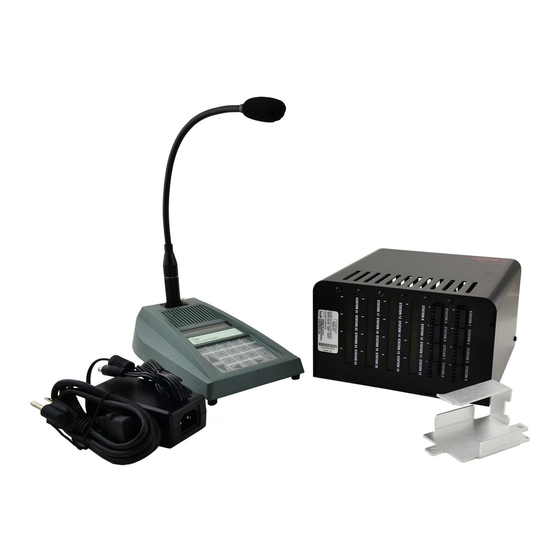
The Performance Series Intercom System consists of: • A minimum of one Model 2475 Station Selector • One Model 2470 Communications Controller • A maximum of 24 Call Stations The system provides two-way audio communication between the Station Selector and the 24 call stations. The system also provides communications between station selectors. -
Page 6: I/O Card And Noise Reduction Module Installation
I/O Board and Noise Reduction Module Installation I/O Card and Noise Reduction Module Installation I/O Card Installation Figure 2. I/O Card Installation Be sure the system is powered off! 1. Remove 4 screws on each side of the Communications Controller cover. 2. -
Page 7: M Model A125, Noise Reduction Module, Installation (Optional)
5. Use upper and lower mounting brackets to secure Noise Reduction Module to Communications Controller chassis as shown in Figure 3. 6. On the Model 2470 circuit board, Set JMP1 to open. LED1 (adjacent to JMP1) blinks when noise reduction module is active. -
Page 8: Component Placement
Component Placement Component Placement This section describes placement of the Performance Series Intercom System components: Communications Controller For proper system operation, locate the Communications Controller: 1. Near the conduit termination of the Call Station wiring. 2. Near the power source. 3. -
Page 9: Call Stations
Performance Series Component Placement Call Stations For proper system operation, install the Call Stations in locations: 1. Chosen for ease of use. 2. At least 48 inches above the pavement. Note Local codes may dictate placement of call stations. Figure 5. Suggested Call Station Placement Station Selectors For proper system operation, locate the Station Selectors: 1. -
Page 10: Wiring The System
Figure 7 shows an overview of the cable types and number of conductors required for each unit. Table 1 shows wire gauge required for different distances between components. We recommend installing a separate power supply transformer (3M part number 78-8095-0910-8), for each Station Selector located over 100 feet from the Communications Controller, The RS 485 cable carries DC power for the Station Selectors, requiring a larger gauge wire. -
Page 11: Configuration Worksheets
The D-2400 System is powered by one power supply that provides power for the Communications Controller and a maximum of three Station Selectors. A separate power supply (3M part number 78-8095-0910-8) must be plugged into each Station Selector that exceeds the three Station Selector limit. We recommend installing a separate power supply if the cable length from the Station Selector to the Communications Controller exceeds 100 feet. -
Page 12: Wiring Communications Controller
Performance Series Initializing the System Wiring Communications Controller Figure 9. Connecting P3 to Communications Controller Refer to Configuration Worksheets 2 and 3 to determine the specific wires and connections to be made. -
Page 13: Initializing The System
Initializing the System System Mode Selection: Before starting the system Initialization process, you must determine the mode of operation. Check the number of speakers at each Multiple Product Dispenser (MPD). Typically, each active side of the MPD is identified as a separate pump: Number of Speakers at MPD... -
Page 14: Initialization Instructions For Pump Mode (Factory Default)
Initializing the System 1. Initialization will erase all memorized parameters and restore factory default values. 2. If Pump Mode (factory default) is desired, initialization is not required. 3. If software is upgraded, the system must be re-initialized. Initialization instructions for Pump Mode (factory default) Init PUMP Mode... -
Page 15: Programming The System
Programming the System If you have not selected the mode of operation (Pump or Island) do so now! See System Mode Selection. Programming State MENU Figure 11. D-2400 Keypad All Station Selectors ship from the factory with a default ID number of 15. It is important to connect and power up each new Station Selector, ONE STATION SELECTOR AT A TIME, when installing a new system. -
Page 16: Error Message
2 and 3 of J8 (RS-485 connector) on the Station Selector. Polarity must be correct! • Call 3M Technical Service to confirm software compatibility between station selector and communication controller. Memorized parameters are given below. These parameters are stored in the EEPROM. - Page 17 A value (On, Off). Default = Off. Enables the VOX (Voice Operated 07:VOX Enable Transmission) feature. {Off} A number (1 to 15 inclusive). Default = 15 (most sensitive). Adjust this value VOX Sensitive to accommodate the ambient noise level at the Station Selector location. Use a {15} lower value for a higher noise environment.
- Page 18 Programming the System 16:Music {On } S=xy: User Name 17: All Call {On } S=xy: User Name 18:Registry {On } S=xy: User Name Sync All Data ‘ T A L K’ = Yes Are You Sure ? ‘T A L K’ = Yes 20:Software Rev Se=a.bc Con=x.yz A value (On, Off) for each Call Station.
-
Page 19: Keypad Function Definitions (For Text Entry) (Programming State)
Keypad Function Definitions (for Text entry) (Programming State) MENU SP-389C Figure 12. D-2400 Key- Key functions are defined below. HOLD (Shift) Shifts between upper and lower case for text data. UP ARROW Increments data by 1. Fields wrap around. DOWN ARROW Decrements data by 1. - Page 20 Programming the System Enters the digit 6 for numeric entry. Enters the following for text entry: Unshifted Shifted Enters the digit 7 for numeric entry. Enters the following for text entry: Unshifted Shifted Enters the digit 8 for numeric entry. Enters the following for text entry: Unshifted Shifted...
-
Page 21: Adjusting The System
Adjusting the System Inbound Audio Volume Level To set the inbound audio volume level: 1. Ask an attendant to stand at a Call Station and push the incoming call button for your Station Selector. 2. Answer the call by pressing the TALK button. 3. -
Page 22: Outbound Music/Messaging Volume Level
Adjusting the System Outbound Music/Messaging Volume Level (Only for systems that use Music/Messaging) To set the outbound Music/Messaging volume level: 1. Follow the directions under the section Programming the System to put the Station Selector in programming mode 2. Locate the Music Volume parameter and follow the instructions in that section. Testing the Functions Perform the following tests after installing the Performance Series D-2400 Intercom System: 1. -
Page 23: Configuration Worksheets
Performance Series Configuration Worksheets Configuration Worksheets... - Page 24 Configuration Worksheets Performance Series...
- Page 25 Performance Series Configuration Worksheets...
- Page 27 Commercial Care Division Food Service Business 3M Center St. Paul, MN 55144-1000 Printed in U.S.A. © 3M 2004 April 78-6912-0739-9 Rev B...