
Related Manuals for Generac Power Systems PowerManager PM-GC


Summary of Contents for Generac Power Systems PowerManager PM-GC
- Page 1 ® POWER SYSTEMS, INC. PowerManager ™ Generator Controller (PM-GC) This manual should remain with the unit. DANGER ONLY QUALIFIED ELECTRICIANS OR CONTRACTORS SHOULD ATTEMPT INSTALLATION!!
-
Page 2: Introduction
Generac strongly recommends that Thank you for purchasing the Modular Power System the operator read this Owner's Manual and thor- by Generac Power Systems. oughly understand all instructions before using this Every effort was expended to make sure that the equipment. -
Page 3: Table Of Contents
Table of Contents PM-GC Introduction ......Inside Front Cover 3.2.5 Touchscreen Operation ....6 3.2.6 Functionality ........6 Read This Manual Thoroughly ......IFC 3.2.7 Software Version Display ....7 Operation and Maintenance ......IFC On Screen Diagnostics ........8 How to Obtain Service ........IFC 3.3.1 Main Diagnostics Menu....8 Authorized Dealer Locator Number ....IFC 3.3.2 Digital Diagnostics ......8... -
Page 4: Safety Rules
IMPORTANT SAFETY INSTRUCTIONS PM-GC SAVE THESE INSTRUCTIONS – This manual contains important instructions that should be followed during installation and maintenance of the generator and batteries. The manufac- turer suggests that these rules for safe operation be copied and posted in potential hazard areas. - Page 5 IMPORTANT SAFETY INSTRUCTIONS PM-GC ELECTRICAL HAZARDS FIRE HAZARDS • All generators covered by this manual produce • For fire safety, the generator(s) must be installed dangerous electrical voltages and can cause fatal and maintained properly. Installation always must electrical shock. Utility power delivers extremely comply with applicable codes, standards, laws and high and dangerous voltages to the transfer switch regulations.
-
Page 6: Section 1 - General Information
Section 1 — General Information PM-GC ◆ EQUIPMENT DESCRIPTION 1.2.4 OVERSPEED SHUTDOWN In a typical standby system, a power outage will be The control system monitors engine speed during sensed by a transfer switch. A time delay is usually engine cranking, start-up, operation and shutdown. incorporated in this signal in order to prevent nui- Engine speed signals are delivered to the control sys- sance tripping of the power system. -
Page 7: Section 2 - Installation
Section 2 — Installation PM-GC FIELD WIRING CONTROL CONSOLE COMPONENTS The PM-GC control module performs all of the gen- Wiring must comply with ALL local and nation- erator control functions within the system. It controls al codes. Only qualified personnel knowledge- engine starting and stopping, engine speed, output able of these local and national codes should voltage and frequency, and monitors engine perform-... -
Page 8: The Optional Display
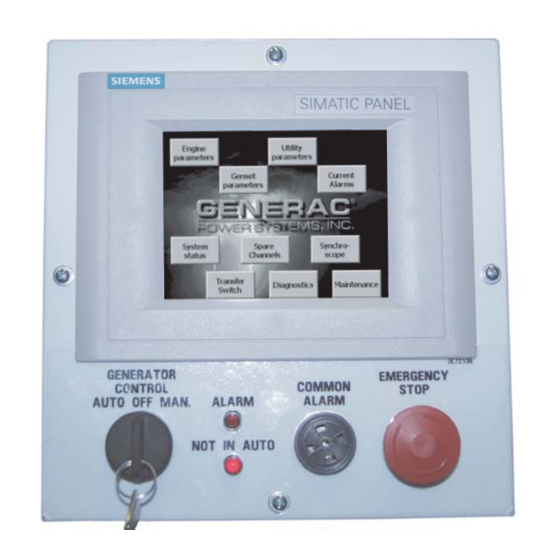
Section 3 — Operation PM-GC THE OPTIONAL DISPLAY EITHER The optional, programmable, remote display can be 1. Switch on the power to the unit. mounted up to 1000 meters away from the generator. 2. During the initialization phase, a menu will Only one display per generator is allowed. -
Page 9: Software Version Display
Section 3 — Operation PM-GC Each screen has some fixed buttons which allow Figure 5 — Typical Menu Screen either access to help text for that screen (context sen- Touch here for engine parameters. (Also see Figure 6.) sitive help) (Figure 2), or return to the main menu (Figure 3). -
Page 10: On Screen Diagnostics
Section 3 — Operation PM-GC • MAINTENANCE SCHEDULE: A display of percent- 3.3.1 MAIN DIAGNOSTICS MENU age remaining before maintenance is required. See Figure 8. Figure 7 — TYPICAL HELP SCREEN - ANALOG HELP 3.3.2 DIGITAL DIAGNOSTICS Inputs to the controller are internally pulled to 5VDC, so to activate an input, short it to ground. -
Page 11: Analog Diagnostics
Section 3 — Operation PM-GC CHANNEL FUNCTION 3.3.3 ANALOG DIAGNOSTICS Utility current sense A By selecting the analog submenu, the sensors con- Utility current sense B nected to each of the analog channels can be interro- gated (Figure 9). The reading displayed is "raw" un- Utility current sense C processed data and is a decimal number ranging Generator current sense A... -
Page 12: Communications Diagnostics
Section 3 — Operation PM-GC goes away AND the alarm has been acknowledged. 3.3.4 COMMUNICATIONS DIAGNOSTICS For shutdown alarms, the alarm cannot be cleared After a port has been selected to test (press the help unless the keyswitch is in the OFF position (the audi- button for a description of the ports), the pseudo ble alarm can be silenced though). -
Page 13: Preheat Time
Section 3 — Operation PM-GC 3.5.3 PREHEAT TIME 3.5.9 WARM UP TIME When a start command is received, the engine may Some applications require that the generator run for require preheating before the generator attempts to a given time before a load is applied. This parameter start. - Page 14 Section 3 — Operation PM-GC High Oil Temperature (Deg. F) Warning Alarm Units Comment Setpoint Shutdown Dialout Common alarm Alarm log Sensor failure detection Shutdown on sensor failure Delay seconds Active Hold of Hold off Hysteresis Deg. F High Coolant Temperature (Deg. F) Setpoint Shutdown Dialout...
- Page 15 Section 3 — Operation PM-GC Low Battery Voltage (1/100ths volt) Warning Alarm Units Comment Setpoint Shutdown Dialout Common alarm Alarm log Sensor failure detection Shutdown on sensor failure Delay 60 seconds seconds Active Hold off Hysteresis 1/100ths volt High Battery voltage (1/100ths volt) Setpoint Shutdown Dialout...
- Page 16 Section 3 — Operation PM-GC Under Speed (rpm) Warning Alarm Units Comment Setpoint Shutdown Dialout Common alarm Alarm log Sensor failure detection Shutdown on sensor failure Delay 0.5 seconds seconds Active Hold off Hysteresis Over Frequency (1/10ths Hz) Setpoint 1/10ths Hz Shutdown Dialout Common alarm...
-
Page 17: Running Hours
Section 3 — Operation PM-GC Critical Low Fuel level (%) Warning Alarm Units Disabled unless probe fitted Setpoint Shutdown Dialout Common alarm Alarm log Sensor failure detection Shutdown on sensor failure Delay 2 seconds seconds Active Always Hysteresis RUNNING HOURS communications will normally be via the GenLink®... -
Page 18: Section 4 - Notes
Section 4 — Notes PM-GC 16 Generac ® Power Systems, Inc. - Page 19 Section 4 — Notes PM-GC Generac ® Power Systems, Inc. 17...
-
Page 20: Section 5 - Warranty
NOTE: ALL UNITS MUST HAVE A START-UP INSPECTION PERFORMED BY AN AUTHORIZED GENERAC DEALER. For a period of 2 (two) years from the date of sale/start date, Generac Power Systems, Inc. will, at its option, repair or replace any part(s) which, upon examination, inspection, and testing by Generac Power Systems or a Generac Power Systems Authorized Warranty Service Facility, is found to be defective under normal use and service, in accordance with the warranty schedule set forth below.