Table of Contents
Advertisement
Quick Links
3M
Water Filtration Products
™
Installation and Operation Instructions for
ScaleGard
HP Reverse Osmosis System
TM
(Original Instructions)
System tested and certified by NSF International
against NSF/ANSI Standard 58 for material safety
and the claims specified on the Performance Data
Sheet and against CSA B483.1.
Installer: Please leave this manual with owner/operator.
Owner/Operator: Please retain for operation and future instructions.
Advertisement
Table of Contents

Related Manuals for 3M ScaleGard HP Reverse Osmosis System


Summary of Contents for 3M ScaleGard HP Reverse Osmosis System
- Page 1 Water Filtration Products ™ Installation and Operation Instructions for ScaleGard HP Reverse Osmosis System (Original Instructions) System tested and certified by NSF International against NSF/ANSI Standard 58 for material safety and the claims specified on the Performance Data Sheet and against CSA B483.1. Installer: Please leave this manual with owner/operator.
-
Page 2: Table Of Contents
Table of Contents Safety Information ........................................3, 4 Parts List ...........................................5 Feedwater Requirements ......................................6 Other Requirements ........................................6 Equipment Set-Up and Installation ....................................7 System Start-Up ........................................10 Routine Maintenance ......................................15, 16 Troubleshooting Guide ......................................17 Product Replacement Parts ...................................... 18 Limited Warranty ......................................Back Cover... -
Page 3: Safety Information
SAFETY INFORMATION Read, understand, and follow all safety information contained in these instructions prior to installation and use of the 3M Water Filtration Products ScaleGard HP reverse osmosis system. Retain these ™ ™ instructions for future reference. Intended use: The ScaleGard HP reverse osmosis system is intended for use in filtering potable water and has not been evaluated for other uses. - Page 4 IF CONNECTION IS MADE TO A POTABLE WATER SYSTEM, THE SYSTEM SHALL BE PROTECTED AGAINST BACKFLOW. NOTICE To reduce the risk associated with property damage due to water leakage or flooding: • Read and follow Use Instructions before installation and use of this system. •...
-
Page 5: Parts List
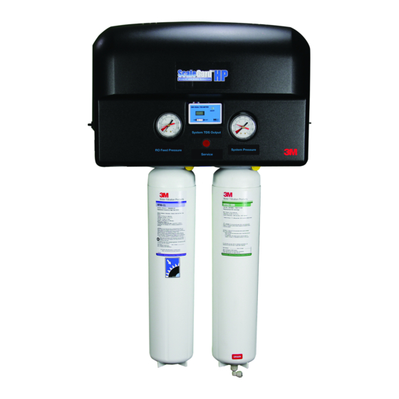
The following parts comprise the ScaleGard HP Reverse Osmosis System. Please unpack the contents from the product box and check to verify that all of the parts listed below are included. Should any parts be missing, please contact 3M Purification Inc. at 1-866-990-9785. Description... -
Page 6: Feedwater Requirements
See safety information regarding reducing the risk associated with property damage due to water leakage or flooding on page 4 prior to set-up and installation of the system. IMPORTANT NOTES • Be sure to confirm that the feedwater falls within the limits shown below. If unsure of the feedwater quality, check with your 3M Water Filtration ™... -
Page 7: Equipment Set-Up And Installation
Equipment Set-Up and Installation NOTICE See safety information regarding reducing the risk associated with property damage due to water leakage or flooding on page 4 prior to set-up and installation of the system. Equipment Location Prior to installing the ScaleGard HP Reverse Osmosis System, carefully plan the installation location for all system components. - Page 8 Wall Mounting the ScaleGard HP Base Unit (Mounting Template included with unit) 1. Draw a level line on the wall where the bracket is to be mounted. Hold bracket key holes on level line and mark locations for screws. 2. Install mounting screws (not included) into each of the initial key holes as shown in figure 2. Be sure to leave 1/8" to 1/4" (0.3 to 0.6 cm) space between the bottom of the screw head and the wall so that the bracket can be hung.
- Page 9 Plumbing Connections 1. Install feed water line to marked “Inlet” 1/2” NPT inlet connection. 2. Install RO water line from marked “Tank Outlet” to pressure tank (Sold Separately). Assemble and install pressure tank fittings per instructions provided with tank. 3. Install RO water line from marked “Equipment Outlet” to the foodservice equipment. Installation of a post filter is recommended downstream of the RO system (Recommended/Sold Separately).
-
Page 10: System Start-Up
System Start Up Required (Sold Separately) 1. Turn on the feedwater supply. Approximate Part Number Pressure Volume Time to Fill 2. Open unit inlet shutoff valve. 5598408 20 gallons (76 liters) 0.6 hours 3. Power the unit by plugging into electrical outlet. 40 gallons (151 liters) 5598409 1.2 hours... - Page 11 Blending Valve Adjustment Instructions: IMPORTANT NOTES: • Typical TDS (Total Dissolved Solids) values for coffee are 80-200 ppm (parts per million) and occasionally lower for espresso, depending upon taste preference. Typical TDS valves for steam and combi ovens are less than 50ppm. •...
- Page 12 Figure 6 — Unit Flow Chart Figure 7 — Electrical Diagram 110V Figure 8 — Electrical Diagram 220V Advanced Diagnosis for Certified Technicians ONLY Caution/Warning: High Voltage in the Control Box Output LED Color Meaning Normal Running Condition Green On when the units power cord is plugged in Green On if PLC is powered with switch in run position Green...
- Page 13 ScaleGard™ HP PLC (Programable Logic Controller) Program Version 9.8 Sequence of Operation Plug unit in, both the Power and Run LED’s are Green A. If Tank Switch is > 60 psi (414 kPa, 4.14 bar) for 110-120VAC systems or 70 psi (483 kPa, 4.83 bar) for 220-240VAC systems, the unit is off on full tank Unit will cycle on when tank switch senses <...
- Page 14 4. Remove the prefilter cartridge from the left cartridge head on the manifold. (See diagram) 5. Install bypass plug (3M part # 6217402) into the left cartridge head on the manifold. (Note: Operating pressure cannot be set/adjusted with used pre-filter cartridges) 6.
-
Page 15: Routine Maintenance
Routine Maintenance Cartridge Change out Instructions (Pre/ Post Filter and RO Membrane Cartridge) WARNING Read entire manual. Failure to follow all guide and rules could cause personal injury or property damage. • Check with your local public works department for plumbing codes. You must follow their guidelines as you install the water filtration system. •... - Page 16 Routine Maintenance Cartridge Change out Instructions (Pre-Filter and RO Membrane Cartridge) RO Membrane Cartridge (green label) Replacement Cont.: 4. Remove sanitary cap from new RO membrane cartridge. Ensure o-rings are seated into their grooves. Remove drain fitting plug from new RO membrane cartridge.
-
Page 17: Troubleshooting Guide
Troubleshooting Guide Technical Support - 1-866-990-9785 Problem Possible Cause Solution Notes Undersized tank for store demand Install additional storage tank capacity Contact Dealer Install RO add-on head and cartridge RO production is to low for store Contact Dealer Upgrade from HFRO 500 to HFRO 700 demand Cartridge Unit Runs Low or Out of Water... -
Page 18: Product Replacement Parts
Replacement Parts Part Number Description 96-410501 Pressure Reducer/Regulator (Contact Dealer) 60-9052 Inlet ball valve (Contact Dealer) 22-518801 Pre-programmed PLC for 5629101 and 6239301 (Contact Dealer) 25-212401 Relay Output Module for 5629101 and 6239301 22-518802 Pre-programmed PLC for 6239302, 629303, 6239304 (Contact Dealer) 22-115401 Relay Output Module for 6239302, 6239303, and 6239304 8500557... - Page 19 Notes...
- Page 20 OUT OF A COURSE OF DEALING, CUSTOM OR USAGE OF TRADE. If the 3M product does not conform to this warranty, then the sole and exclusive remedy is, at 3M’s option, replacement of the 3M product or refund of the purchase price.