Table of Contents
Advertisement
Quick Links
Advertisement
Table of Contents

Related Manuals for National Instruments SCXI-1521


Summary of Contents for National Instruments SCXI-1521
- Page 1 SCXI SCXI-1521/B User Manual SCXI-1521/B User Manual March 2006 373749B-01...
- Page 2 Thailand 662 278 6777, United Kingdom 44 0 1635 523545 For further support information, refer to the Signal Conditioning Technical Support Information document. To comment on National Instruments documentation, refer to the National Instruments Web site at ni.com/info and enter the info code feedback.
- Page 3 Instruments Corporation. National Instruments respects the intellectual property of others, and we ask our users to do the same. NI software is protected by copyright and other intellectual property laws. Where NI software may be used to reproduce software or other materials belonging to others, you may use NI software only to reproduce materials that you may reproduce in accordance with the terms of any applicable license or other legal restriction.
- Page 4 Bold text in this font denotes the messages and responses that the computer monospace bold automatically prints to the screen. This font also emphasizes lines of code that are different from the other examples. SCXI-1521/B SCXI-1521/B refers to both the SCXI-1521 and the SCXI-1521B module, unless otherwise noted.
-
Page 5: Table Of Contents
National Instruments Documentation ................1-3 Installing the Application Software, NI-DAQ, and the DAQ Device ......1-4 Installing the SCXI-1521/B ...................1-4 Connecting the SCXI-1521/B to an E/M Series DAQ Device for Multiplexed Scanning in a PXI/SCXI Combination Chassis .......1-4 Verifying and Self-Testing the Installation .............1-5 Troubleshooting the Self-Test Verification ..............1-6... - Page 6 Contents Software Scaling and Equations ..............4-3 Quarter-Bridge Type I..................4-3 SCXI-1521/B Theory of Operation ................4-5 Quarter-Bridge Completion ................4-7 Excitation ......................4-8 Offset Null Compensation ................4-8 Shunt Calibration .................... 4-9 Modes of Operation ..................4-9 Theory of Multiplexed Mode Operation .......... 4-9...
- Page 7 Basic Wheatstone Bridge Circuit Diagram ...........4-1 Figure 4-2. Quarter-Bridge Type I Measuring Axial and Bending Strain ....4-3 Figure 4-3. Quarter-Bridge Type I Circuit Diagram ..........4-4 Figure 4-4. Block Diagram of SCXI-1317 and SCXI-1521/B Combination...4-6 Figure 5-1. Typical Program Flowchart..............5-2 Figure A-1. SCXI-1521/B Dimensions..............A-4 Figure B-1.
-
Page 8: About The Scxi-1521/B
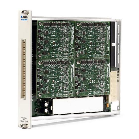
Measurement & Automation Explorer (MAX) or through NI-DAQmx property nodes. The SCXI-1521 has 350 Ω completion resistors while the SCXI-1521B has 120 Ω completion resistors. The SCXI-1521/B includes the following functionality: •... -
Page 9: Table 1-1. Accessories Available For The Scxi-1521/B
Table 1-1. Accessories Available for the SCXI-1521/B Accessory Description SCXI-1317 Screw terminal block—Mounts on the front of the SCXI-1521/B module and provides easy access to the terminal for field wiring connections. SCXI-1310 Connector and shell assembly—Provides 96 eyelet-type terminals for easy hook-and-solder signal connection and custom mass termination connectivity. -
Page 10: National Instruments Documentation
About the SCXI-1521/B National Instruments Documentation The SCXI-1521/B User Manual is one piece of the documentation set for data acquisition (DAQ) systems. You could have any of several types of manuals depending on the hardware and software in the system. Use the manuals you have as follows: •... -
Page 11: Installing The Application Software, Ni-Daq, And The Daq Device
DAQ device to which you will connect the SCXI-1521/B. NI-DAQmx 7.3 or later is required to configure and program the SCXI-1521/B module. If you do not have NI-DAQmx 7.3 or later, you can either contact an NI sales representative to request it on a CD or download the latest NI-DAQ version from ni.com... -
Page 12: Verifying And Self-Testing The Installation
DAQ device in a PXI/SCXI combination chassis, complete the following steps: No cables are required between the SCXI-1521/B and the E/M Series DAQ device Notes if the E/M Series DAQ device is installed in the right-most PXI slot. You can configure this device to control the SCXI system using an internal bus that connects the PXI chassis to the SCXI chassis. -
Page 13: Troubleshooting The Self-Test Verification
Chapter 1 About the SCXI-1521/B If you are using NI-DAQmx, you can verify each module in the SCXI chassis. To test the successful installation of each module, complete the following steps: Verify that the chassis is powered on and correctly connected to an E/M Series DAQ device. - Page 14 Chapter 1 About the SCXI-1521/B – Make sure you are using the correct NI cable assembly for your application. – Test the E/M Series DAQ device to verify it is working properly. Refer to the E/M Series DAQ device help file for more information.
-
Page 15: Connecting Signals
Connecting Signals This chapter describes how to connect quarter-bridge strain gauges to the SCXI-1521/B through the SCXI-1317. It also provides the front and rear signal pin assignments of the module. To connect a quarter-bridge strain gauge in configuration type I with either a 2- or 3-wire strain gauge, refer to the SCXI-1317 Terminal Block Installation Guide. -
Page 16: Table 2-1. Front Signal Pin Assignments
AI 19 EX + 20 QTR 20 AI 20 EX + 21 QTR 21 AI 21 RSVD QTR 22 AI 22 RSVD QTR 23 AI 23 RSVD EX + 22 RSVD RSVD EX + 23 RSVD SCXI-1521/B User Manual ni.com... - Page 17 SCXI-1521/B and the connected E/M Series DAQ device. Table 2-2 shows the rear signal connector and lists the pin assignments for the SCXI-1521/B. Grounding signals AI GND and OUT REF provide reference signals needed in the various analog input referencing modes on the E/M Series DAQ device.
-
Page 18: Table 2-2. Rear Signal Pin Assignments
DIG GND — 39 40 41 42 — AI HOLD COMP, AI HOLD 43 44 SER CLK — 45 46 — — 47 48 49 50 — — — — — SYNC — — — — SCXI-1521/B User Manual ni.com... -
Page 19: Table 2-3. Scxi-1521/B Communication Signals
Connecting Signals In multiplexed mode, the AI 0 signal pair is used for sending all 24 channels of the SCXI-1521/B, and analog signals from other modules, to the connected E/M Series DAQ device. If the module is cabled directly to the E/M Series DAQ device, the other analog channels of the E/M Series DAQ device are unavailable for general-purpose analog input because they are connected to active signals on the SCXI-1521/B amplifier. - Page 20 Chapter 2 Connecting Signals Table 2-3. SCXI-1521/B Communication Signals (Continued) NI-DAQmx SCXI Signal Device Signal Name Name Direction Description SCAN CLK AI HOLD COMP, Input Scan clock—A rising edge AI HOLD indicates to the scanned SCXI module that the E/M Series DAQ...
-
Page 21: Configuring And Testing
Configuring and Testing This chapter describes how to configure the SCXI-1521/B in MAX for use with NI-DAQmx. It also describes how to create and test a virtual channel, global channel, and/or task. SCXI-1521/B Software Configurable Settings This section describes how to set the voltage excitation level, and... -
Page 22: Gain/Input Range
Gain/input range is a software-configurable setting that allows you to choose the appropriate amplification for your application. The SCXI-1521/B has a fixed gain of 42 V/V. Additional gain settings are available on the digitizer device. In most applications NI-DAQmx selects the gain for you based on the specified input range. -
Page 23: Ni-Daqmx
Strain and custom voltage with excitation are the most commonly used NI-DAQmx task or NI-DAQmx Global Channel types with the SCXI-1521/B. The following list describes the settings you can use in MAX and where they are located: •... - Page 24 Developing Your Application in NI-DAQmx section of Chapter 5, Using the SCXI-1521/B, for more information about adding channels. Enter the specific values for your application in the Settings tab. Context help information for each setting is provided on the right side of the screen.
-
Page 25: Verifying The Signal
NI-DAQmx. Verifying the Signal in NI-DAQmx Using a Task or Global Channel Complete the following steps to verify the SCXI-1521/B signals: Open the channel or task you created in the... -
Page 26: Theory Of Operation
A physical phenomenon, such as a change in strain or temperature applied to a specimen, changes the resistance of the sensing elements in the © National Instruments Corporation SCXI-1521/B User Manual... -
Page 27: Acronyms, Formulas, And Variable Definitions
(unstrained) – ------------------------------------------------------------------------------ - SCXI-1521/B User Manual ni.com... -
Page 28: Software Scaling And Equations
A quarter-bridge type I has the following characteristics: • A single active strain-gauge element is mounted in the principle direction of axial or bending strain. • A passive quarter-bridge completion resistor (dummy resistor) is required in addition to half-bridge completion. © National Instruments Corporation SCXI-1521/B User Manual... -
Page 29: Figure 4-3. Quarter-Bridge Type I Circuit Diagram
To convert voltage readings to strain units use, the following equation: 4 – V strain ε ( ) × ------------------------------- ----- - GF 1 where is the nominal gauge resistance of the sensor. is the lead resistance. GF is the Gauge Factor. SCXI-1521/B User Manual ni.com... -
Page 30: Scxi-1521/B Theory Of Operation
(∼ <10 ft), depending on the wire gauge. For example 10 ft of 24-AWG copper wire has a lead resistance of 0.25 Ω. SCXI-1521/B Theory of Operation This section includes a brief overview and a detailed discussion of the circuit features of the module. -
Page 31: Figure 4-4. Block Diagram Of Scxi-1317 And Scxi-1521/B Combination
Chapter 4 Theory of Operation Rear Signal Connector SCXIbus Connector Analog Multiplexer Shunt Shunt Calibration Calibration Switch Switch Quarter-Bridge Quarter-Bridge Completion Completion Figure 4-4. Block Diagram of SCXI-1317 and SCXI-1521/B Combination SCXI-1521/B User Manual ni.com... -
Page 32: Quarter-Bridge Completion
The input amplification stage is followed by an additional amplification and lowpass filter stage before reaching the output multiplexer. The SCXI-1521/B has a fixed lowpass filter with a 3 dB cutoff of 10 Hz. The SCXI-1521/B has a fixed gain of 42 V/V. -
Page 33: Excitation
Theory of Operation Excitation You can set the excitation voltage of the SCXI-1521/B from 0 to 5 V in 1,023 steps. The excitation voltage is buffered on a per channel basis to prevent excitation load variation errors from interfering with other channels. -
Page 34: Shunt Calibration
Performing a shunt calibration before an offset null compensation causes improper gain adjustment because the offset signal voltage is compensated multiple times. Modes of Operation The SCXI-1521/B operates in multiplexed mode, passing the conditioned signals to the digitizing DAQ device. © National Instruments Corporation... -
Page 35: Theory Of Multiplexed Mode Operation
DAQ device. There are several possible scenarios for routing signals from the multiplexed modules to the DAQ device. If the scanned SCXI-1521/B module is not directly cabled to the DAQ device, the module sends its signals through the SCXIbus to the cabled module. -
Page 36: Using The Scxi-1521/B
7.0 or later of an NI ADE. This section describes how to configure and use NI-DAQmx to control the SCXI-1521/B in LabVIEW, LabWindows/CVI, and Measurement Studio. These ADEs provide greater flexibility and access to more settings than MAX, but you can use ADEs in conjunction with MAX to quickly create a customized application. -
Page 37: Figure 5-1. Typical Program Flowchart
Chapter 5 Using the SCXI-1521/B Create Task Using DAQ Assistant? Create a Task Programmatically Create Task in DAQ Assistant or MAX Create Strain or Custom Create Another Voltage with Excitation Channel Channel? Hardware Timing/Triggering? Further Configure Channels? Adjust Timing Settings... -
Page 38: General Discussion Of Typical Flow Chart
Chapter 5 Using the SCXI-1521/B General Discussion of Typical Flow Chart The following sections briefly discuss some considerations for a few of the steps in Figure 5-1. These sections are meant to give an overview of some of the options and features available when programming with NI-DAQmx. -
Page 39: Configuring Channel Properties
Configuring Channel Properties All ADEs used to configure the SCXI-1521/B access an underlying set of NI-DAQmx properties. Table 5-1 shows some of these properties. You can use Table 5-1 to determine what kind of properties you need to set to configure the module for your application. -
Page 40: Perform Offset Null Compensation
ADE help file. Perform Offset Null Compensation The SCXI-1521/B provides offset null compensation circuitry to adjust signal voltages to proper levels when the strain gauge is at rest (unstrained). You can use a strain task or global channel to perform offset null compensation. -
Page 41: Perform Shunt Calibration
Chapter 5 Using the SCXI-1521/B Perform Shunt Calibration Shunt calibration is a process used to obtain a gain adjust factor, which corrects for system gain error. You can use a strain task or global channel to perform shunt calibration. The shunt calibration is performed during the configuration of the global channel(s). -
Page 42: Developing An Application Using Labview
This section describes in more detail the steps shown in the typical program flowchart in Figure 5-1, such as how to create a task in LabVIEW and configure the channels of the SCXI-1521/B. If you need more information or for further instructions, select Help»VI, Function, & How-To Help from the LabVIEW menu bar. - Page 43 Chapter 5 Using the SCXI-1521/B Table 5-2. Programming a Task in LabVIEW (Continued) Flowchart Step VI or Program Step Configure Channels DAQmx Channel Property Node, refer to the Using a DAQmx (optional) Channel Property Node in LabVIEW section for more information.
-
Page 44: Using A Daqmx Channel Property Node In Labview
Chapter 5 Using the SCXI-1521/B Using a DAQmx Channel Property Node in LabVIEW You can use property nodes in LabVIEW to manually configure the channels. To create a LabVIEW property node, complete the following steps: Launch LabVIEW. Create the property node in a new VI or in an existing VI. -
Page 45: Specifying Channel Strings In Ni-Daqmx
• Excitation on a particular SCXI-1521/B channel—for example SC1Mod1/_Vex0 SC1Mod1/_Vex1 Once you have a task containing SCXI-1521/B channels, you can set the properties of the channels programmatically using the DAQmx Channel Property Node. Text Based ADEs You can use text based ADEs such as LabWindows/CVI, Measurement Studio, Visual Basic, .NET, and C# to create code for using the... -
Page 46: Measurement Studio (Visual Basic, .Net, And C#)
Figure 5-1. You can then use the appropriate function calls to modify the task. This example creates a new task and configures an NI-DAQmx strain channel on the SCXI-1521/B. You can use the same functions for Visual Basic .NET and C#. -
Page 47: Other Application Documentation And Material
There are two types of calibration important to verifying the accuracy of a strain measurement system. Device calibration ensures the accuracy of the SCXI-1521/B. System calibration involves removing potential error-causing variables such as offset and verifying the accuracy of the strain element through shunt calibration. -
Page 48: Calibrating The Scxi-1521/B
Chapter 5 Using the SCXI-1521/B Calibrating the SCXI-1521/B The SCXI-1521/B is shipped with a calibration certificate and is calibrated at the factory to the specifications described in Appendix A, Specifications. Calibration constants are stored inside the calibration EEPROM and provide software correction values your application development software uses to correct the measurements for errors in the module. -
Page 49: Appendix A Specifications
Specifications This appendix lists the specifications for the SCXI-1521/B modules. These specifications are typical at 25 °C unless otherwise noted. Analog Input Number of channels ....... 24 Voltage gain ........... 42 Input coupling ........DC Overvoltage protection......±11 V powered on and off Inputs protected........ - Page 50 Offset drift ..........±3 µV/°C max ±1 µV/°C typ Offset Null Compensation Range ............±0.45% of excitation voltage Resolution ..........4,096 counts of resolution (±9,600 µε offset null compensation range, 4.4 µε resolution for GF = 2.0) Includes excitation voltage noise contribution. SCXI-1521/B User Manual ni.com...
-
Page 51: Scxi-1521/B Dimensions
Protection ..........Surge arrestors in parallel with excitation terminals, shunt to ground, short circuit protected Bridge Completion SCXI-1521 ..........350 Ω, 0.1%, 2 ppm/°C max, 55 mW at 50 °C SCXI-1521 long-term stability....0.02%/yr SCXI-1521B........... 120 Ω, 0.1%, 2 ppm/°C max, 55 mW at 50 °C... - Page 52 V– ............–18.5 to –25 VDC, –170 mA min +5 V ............+4.75 to 5.25 VDC, 50 mA min Physical 3.0 cm (1.2 in.) 17.2 cm (6.8 in.) 18.8 cm (7.4 in.) Figure A-1. SCXI-1521/B Dimensions Weight ............748 gm (26.4 oz) SCXI-1521/B User Manual ni.com...
- Page 53 Humidity ..........10 to 90% RH, noncondensing Maximum altitude ........2,000 m Pollution Degree (indoor use only) ..2 Safety The SCXI-1521/B is designed to meet the requirements of the following standards of safety for electrical equipment for measurement, control, and laboratory use: •...
- Page 54 (Class A) Compliant Note For EMC compliance, operate this device with shielded cabling. CE Compliance The SCXI-1521/B meets the essential requirements of applicable European Directives, as amended for CE marking, as follows: Low-Voltage Directive (safety)....73/23/EEC Electromagnetic Compatibility Directive (EMC) ........89/336/EEC...
-
Page 55: Removing The Scxi-1521/B
Power off the chassis. Do not remove the SCXI-1521/B module from a chassis that is powered on. If the SCXI-1521/B is the module cabled to the E/M Series DAQ device, disconnect the cable. © National Instruments Corporation SCXI-1521/B User Manual... - Page 56 Appendix B Removing the SCXI-1521/B Remove any terminal block that connects to the SCXI-1521/B. Rotate the thumbscrews that secure the SCXI-1521/B to the chassis counterclockwise until they are loose, but do not completely remove the thumbscrews. Remove the SCXI-1521/B by pulling steadily on both thumbscrews until the module slides completely out.
- Page 57 This appendix lists common questions related to the use of the SCXI-1521/B. Which version of NI-DAQ works with the SCXI-1521/B, and how do I get the most current version of NI-DAQ? You must have NI-DAQmx 7.3 or later. Go to and click Download ni.com...
-
Page 58: Table C-1. Digital Signals On The Scxi-1521/B
Appendix C Common Questions If the SCXI-1521/B module is not cabled directly to a E/M Series DAQ device, can I measure conditioned signals for channels 0 through 7 at the rear connector, for example—using a scope, DMM, or custom acquisition system? NI does not support or recommend this usage. - Page 59 A cabled module is the module connected directly to the E/M Series DAQ device. Can I use the SCXI-1521/B with a version of NI-DAQ that works under the Macintosh Operating System (Mac OS)? No, as of NI-DAQ 6.6.1. Check the release notes of later versions of NI-DAQ at for updates.
- Page 60 Appendix C Common Questions What is the power-on state of the SCXI-1521/B multiplexer, analog bus switches, and configuration settings? The multiplexer, analog bus switches, and configuration settings are not in a known state immediately after power on. All hardware settings are programmed automatically when beginning an acquisition in LabVIEW or a test panel in MAX.
- Page 61 – Negative of, or minus. ± Plus or minus. < Less than. Per. ° Degree. ε Strain. ε Simulated strain. υ Poisson’s ratio. Ω Ohms. + 5 V (signal) +5 VDC source signal. © National Instruments Corporation SCXI-1521/B User Manual...
- Page 62 Fixed-valued resistors used to complete a wheatstone bridge when fewer resistors than four of the bridge elements are working strain gauges. Butterworth filter A lowpass filter whose characteristics are optimized for maximum flatness in the passband. Celsius. European emissions control standard. SCXI-1521/B User Manual ni.com...
- Page 63 (2) Collecting and measuring the same kinds of electrical signals with A/D and/or DIO boards plugged into a computer, and possibly generating control signals with D/A and/or DIO boards in the same computer. DAQ device A data acquisition device. © National Instruments Corporation SCXI-1521/B User Manual...
- Page 64 A type of signal conditioning that allows you to remove unwanted frequency components from the signal you are trying to measure. flexible scanning The hardware capability to sequence through channels in a scan list in any order. SCXI-1521/B User Manual ni.com...
- Page 65 Identifier. Inch or inches. input impedance The measured resistance and capacitance between the input terminals of a circuit. instrumentation A very accurate differential amplifier with a high input impedance. amplifier © National Instruments Corporation SCXI-1521/B User Manual...
- Page 66 An SCXI operating mode in which analog input channels are multiplexed into one module output so that the cabled E/M Series DAQ device has access to the module’s multiplexed output as well as the outputs of all other multiplexed modules in the chassis. SCXI-1521/B User Manual ni.com...
- Page 67 A term used to describe the quality of a lowpass filter. In general, the more poles a lowpass filter has, the better it attenuates frequencies beyond the cutoff frequency. port A digital port consisting of multiple I/O lines on a E/M Series DAQ device. Peak to peak. © National Instruments Corporation SCXI-1521/B User Manual...
- Page 68 RSVD Reserved bit, pin, or signal. Referred To Input—Calculates a specification relative to the input range. Seconds. Samples. Samples Per Second—Used to express the rate at which an E/M Series DAQ device samples an analog signal. SCXI-1521/B User Manual ni.com...
- Page 69 Slot 0 Refers to the power supply and control circuitry in the SCXI chassis. SLOT 0 SEL Slot 0 select signal. SPI CLK Serial peripheral interface clock signal. © National Instruments Corporation SCXI-1521/B User Manual...
- Page 70 A source that supplies the voltage needed by a sensor for its proper operation. --------- - --------- - – STRAINED UNSTRAINED SCXI-1521/B User Manual G-10 ni.com...
- Page 71 A circuit arrangement consisting of four resistive elements in a diamond pattern; with excitation voltage applied across two opposing terminals, small resistance changes in the elements are easily detected by measuring voltage changes across the remaining two terminals. © National Instruments Corporation G-11 SCXI-1521/B User Manual...
- Page 72 Index analog input, specifications, A-1 DAQ devices cabling restrictions with plug-in E Series DAQ devices, C-3 connecting to SCXI-1521/B for multiplexed block diagram, 4-6 scanning bridge completion specifications, A-3 in PXI combination chassis, 1-4 bridge configuration unavailable digital lines, C-2...
- Page 73 DAQ device for questions about, C-4 multiplexed scanning in PXI combination chassis, 1-4 removing SCXI-1521/B from Measurement & Automation operation of SCXI-1521/B. See theory of Explorer, B-1 operation from SCXI chassis, B-1 software installation, 1-4 internal calibration. See calibration...
- Page 74 A-5 excitation, A-3 safety specifications, A-5 filter, A-2 SCXI chassis maximum working voltage, A-5 installing SCXI-1521/B, 1-4 null compensation, A-2 removing SCXI-1521/B, B-1 physical, A-4 SCXI-1310 connector and shell assembly, 1-2 power requirements (from SCXI SCXI-1317 terminal block, C-4...