National Instruments SCXI SCXI-1102 User Manual
Hide thumbs
Also See for SCXI SCXI-1102:
- User manual (48 pages) ,
- Calibration procedure (18 pages) ,
- Application note (10 pages)
Table of Contents
Advertisement
Quick Links
Advertisement
Table of Contents
Troubleshooting

Related Manuals for National Instruments SCXI SCXI-1102


Summary of Contents for National Instruments SCXI SCXI-1102
- Page 1 SCXI SCXI-1102/B/C User Manual SCXI-1102/B/C User Manual April 2006 371975D-01...
- Page 2 Thailand 662 278 6777, United Kingdom 44 0 1635 523545 For further support information, refer to the Technical Support Information document. To comment on National Instruments documentation, refer to the National Instruments Web site at ni.com/info and enter the info code feedback.
- Page 3 Instruments Corporation. National Instruments respects the intellectual property of others, and we ask our users to do the same. NI software is protected by copyright and other intellectual property laws. Where NI software may be used to reproduce software or other materials belonging to others, you may use NI software only to reproduce materials that you may reproduce in accordance with the terms of any applicable license or other legal restriction.
- Page 4 Conventions The following conventions are used in this manual: <> Angle brackets that contain numbers separated by an ellipsis represent a range of values associated with a bit or signal name—for example, AO <3..0>. » The » symbol leads you through nested menu items and dialog box options to a final action.
-
Page 5: Table Of Contents
Chapter 1 About the SCXI-1102/B/C What You Need to Get Started ..................1-2 National Instruments Documentation ................1-3 Installing Application Software, NI-DAQ, and the DAQ Device .........1-4 Installing the SCXI-1102/B/C Module into the SCXI Chassis .......1-4 Connecting the SCXI-1102/B/C in an SCXI Chassis to an E/M Series DAQ Device for Multiplexed Scanning ......1-5... - Page 6 Contents Configurable Settings in MAX..................3-2 NI-DAQmx ..................... 3-2 Creating a Global Channel or Task ..........3-3 Traditional NI-DAQ (Legacy) ................ 3-4 Configuring Module Property Pages in Traditional NI-DAQ (Legacy) ............3-4 Creating a Virtual Channel ............... 3-5 Verifying the Signal ...................... 3-5 Verifying the Signal in NI-DAQmx Using a Task or Global Channel ...
- Page 7 Calibration ........................5-18 Appendix A Specifications Appendix B Using SCXI Channel Strings with Traditional NI-DAQ (Legacy) 7.0 or Later Appendix C Removing the SCXI-1102/B/C Appendix D Common Questions Appendix E Current-Loop Receivers Glossary Index © National Instruments Corporation SCXI-1102/B/C User Manual...
- Page 8 Contents Figures Figure 2-1. Ground-Referenced Signal Connection ..........2-5 Figure 2-2. Floating Signal Connection Referenced to Chassis Ground....2-6 Figure 4-1. SCXI-1102/B/C Module Block Diagram..........4-1 Figure 5-1. Typical Program Flowchart for Voltage Measurement Channels ..5-2 Figure 5-2. Typical SCXI-1102/B/C Program Flow with Traditional NI-DAQ (Legacy) ............
-
Page 9: About The Scxi-1102/B/C
DAQ device, greatly increasing the number of analog input signals that you can digitize. Detailed specifications of the SCXI-1102/B/C modules are listed in Appendix A, Specifications. © National Instruments Corporation SCXI-1102/B/C User Manual... -
Page 10: What You Need To Get Started
Chapter 1 About the SCXI-1102/B/C What You Need to Get Started To set up and use the SCXI-1102/B/C module, you need the following: ❑ Hardware – At least one of the following modules: • SCXI-1102 • SCXI-1102B • SCXI-1102C – At least one of the following terminal blocks: •... -
Page 11: National Instruments Documentation
E/M Series DAQ device that plugs into or is connected to the computer. Use this documentation for hardware installation and configuration instructions, specification information about the E/M Series DAQ device, and application hints. © National Instruments Corporation SCXI-1102/B/C User Manual... -
Page 12: Installing Application Software, Ni-Daq, And The Daq Device
About the SCXI-1102/B/C • Software documentation—You may have both application software and NI-DAQ software documentation. National Instruments (NI) application software includes LabVIEW, LabWindows/CVI, and Measurement Studio. After you set up the hardware system, use either your application software documentation or the NI-DAQ documentation to help you write your application. -
Page 13: Connecting The Scxi-1102/B/C In An Scxi Chassis To An E/M Series Daq Device For Multiplexed Scanning
NI recommends auto-detecting modules for the first time configuration of the chassis. Installing SCXI Using Traditional NI-DAQ (Legacy) in Software Refer to the SCXI Quick Start Guide for information on installing modules using Traditional NI-DAQ (Legacy) in software. © National Instruments Corporation SCXI-1102/B/C User Manual... -
Page 14: Manually Adding Modules In Traditional Ni-Daq (Legacy)
Chapter 1 About the SCXI-1102/B/C Manually Adding Modules in Traditional NI-DAQ (Legacy) If you did not auto-detect the SCXI modules, you must manually add each of the modules. Refer to the SCXI Quick Start Guide to manually add modules. Note NI recommends auto-detecting modules for the first time configuration of the chassis. - Page 15 After checking the preceding items, return to the Troubleshooting the Self-Test Verification section and retest the SCXI chassis. If these measures do not successfully configure the SCXI system, contact NI. Refer to the Technical Support Information document for contact information. © National Instruments Corporation SCXI-1102/B/C User Manual...
-
Page 16: Troubleshooting In Traditional Ni-Daq (Legacy)
Chapter 1 About the SCXI-1102/B/C Troubleshooting in Traditional NI-DAQ (Legacy) • If you get the message Unable to test chassis at this time you have not designated at least one module as connected to a E Series DAQ device. Refer to the Traditional NI-DAQ (Legacy) section of Chapter 3,... -
Page 17: Connecting The Signals
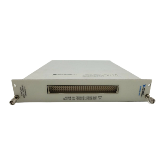
If you are using a custom cable or connector block, refer to the Front Connector section. Front Connector Table 2-1 shows the pin assignments for the SCXI-1102/B/C module front connector. © National Instruments Corporation SCXI-1102/B/C User Manual... -
Page 18: Table 2-1. Scxi-1102/B/C Front Signal Pin Assignments
Chapter 2 Connecting the Signals Table 2-1. SCXI-1102/B/C Front Signal Pin Assignments Front Connector Diagram Pin Number Column A Column B Column C CH GND AI 0 – AI 0 + Column AI 1 – AI 1 + AI 2 – AI 2 + AI 3 –... -
Page 19: Front Connector Signal Descriptions
Each channel includes input protection circuitry to withstand the accidental application of voltages up to ±42 VAC peak or 60 VDC. © National Instruments Corporation SCXI-1102/B/C User Manual... - Page 20 Chapter 2 Connecting the Signals Exceeding the input damage level (±42 VAC peak or 60 VDC between input Cautions channels and chassis ground) can damage the SCXI-1102/B/C module, the SCXIbus, and the DAQ device. NI is not liable for any injuries resulting from such signal connections. Applying a voltage greater than ±42 VAC peak or 60 VDC to the SCXI-1102/B/C is an electrical shock hazard.
-
Page 21: Figure 2-1. Ground-Referenced Signal Connection
Chapter 2 Connecting the Signals CH 0+ CH 0– – – CH 1+ CH 1– – CH 31+ CH 31– – SCXI - 1102/B/C Figure 2-1. Ground-Referenced Signal Connection © National Instruments Corporation SCXI-1102/B/C User Manual... -
Page 22: Cold-Junction Sensor Connection
Chapter 2 Connecting the Signals CH 0+ CH 0– – Floating Signal – CH 1+ CH 1– – bias Make This Connection CH 31+ to Ground CH 31– Reference – the Signal CH GND Referenced to Chassis Ground SCXI - 1102/B/C Figure 2-2. -
Page 23: Table 2-3. Rear Signal Pin Assignments
CH 0 + CH 0 – OUT REF D GND SER DAT IN SER DAT OUT DAQ D*/A SLOT 0 SEL* D GND AI HOLD COMP, AI HOLD SER CLK RSVD RSVD NC—No Connection © National Instruments Corporation SCXI-1102/B/C User Manual... -
Page 24: Rear Signal Connector Descriptions
Chapter 2 Connecting the Signals Rear Signal Connector Descriptions The rear signal connector on the cabled module is the interface between the DAQ device and all modules in the SCXI chassis. CH 0 is used to differentially multiplex all 32 channels, the CJ sensor, and analog signals from the modules to the connected DAQ device. -
Page 25: Connecting Thermocouples
Refer to the SCXI-1581 User Manual for information about connecting RTDs and for additional RTD theory. Connecting a Current-Loop Receiver Refer to Appendix E, Current-Loop Receivers, for information about connecting current loop receivers. © National Instruments Corporation SCXI-1102/B/C User Manual... -
Page 26: Configuring And Testing
When using a terminal block that has a CJ sensor for thermocouple measurements, you can set the CJC source as internal, which scans the sensor at the beginning of each measurement and scales the readings accordingly. © National Instruments Corporation SCXI-1102/B/C User Manual... -
Page 27: Configurable Settings In Max
Chapter 3 Configuring and Testing Configurable Settings in MAX If you are not using an NI ADE, using an NI ADE prior to version 7.0, or are using Note an unlicensed copy of an NI ADE, additional dialog boxes from the NI License Manager appear allowing you to create a task or global channel in unlicensed mode. -
Page 28: Creating A Global Channel Or Task
Configure the input signal range using either NI-DAQmx Task or NI-DAQmx Global Channel. When you set the minimum and maximum range of NI-DAQmx Task or NI-DAQmx Global Channel, the driver selects the best gain for the measurement. © National Instruments Corporation SCXI-1102/B/C User Manual... -
Page 29: Traditional Ni-Daq (Legacy)
Chapter 3 Configuring and Testing You also can set it through your application. Refer to Chapter 3, Configuring and Testing, for more information. 10. If you are creating a task and want to set timing or triggering controls, enter the values in the Task Timing and Task Triggering tabs. Traditional NI-DAQ (Legacy) Using Traditional NI-DAQ (Legacy), you can configure software settings, such as gain/input signal range in the following three ways:... -
Page 30: Creating A Virtual Channel
Next as needed. Click Finish. Verifying the Signal This section describes how to take measurements using test panels in order to verify signal, and configuring and installing a system in NI-DAQmx and Traditional NI-DAQ (Legacy). © National Instruments Corporation SCXI-1102/B/C User Manual... -
Page 31: Verifying The Signal In Ni-Daqmx Using A Task Or Global Channel
Chapter 3 Configuring and Testing Verifying the Signal in NI-DAQmx Using a Task or Global Channel You can verify the signals on the SCXI-1102/B/C using NI-DAQmx by completing the following steps: Click + next to Data Neighborhood. Click + next to NI-DAQmx Tasks. Click the task. -
Page 32: Verifying The Signal Using Channel Strings
Enter the channel string. Enter the input limits. Select the Data Mode. Select the Y Scale Mode. Refer to the LabVIEW Measurements Manual for more information and for proper formatting of channel strings for different uses. © National Instruments Corporation SCXI-1102/B/C User Manual... -
Page 33: Theory Of Operation
Register CJSENSOR Lowpass Buffer Filter Calibration EEPROM Figure 4-1. SCXI-1102/B/C Module Block Diagram The major components of the SCXI-1102/B/C modules are as follows: • Rear signal connector • SCXIbus connector • SCXIbus interface © National Instruments Corporation SCXI-1102/B/C User Manual... -
Page 34: Rear Signal Connector, Scxibus Connector, And Scxibus Interface
Chapter 4 Theory of Operation • Digital control circuitry • Analog circuitry The SCXI-1102/B/C modules consist of 32 multiplexed input channels, each with a software-programmable gain of 1 or 100. Each input channel has its own lowpass filter. The SCXI-1102/B/C modules also have a digital section for automatic control of channel scanning, temperature sensor selection, and gain selection. -
Page 35: Theory Of Multiplexed Operation
The cabled module, whose routing is controlled by the SCXI chassis, routes the SCXIbus signals to the E/M Series DAQ device through the CH 0 pin on its rear signal connector. © National Instruments Corporation SCXI-1102/B/C User Manual... - Page 36 Chapter 4 Theory of Operation If the E/M Series DAQ device scans the cabled module, the module routes its input signals through the CH 0 pin on its rear signal connector to the E/M Series DAQ device CH 0. Multiplexed mode scanning acquisition rates have limitations that are determined based on the hardware in the system, and the mode of operation.
-
Page 37: Using The Scxi-1102/B/C
Typical Program Flowchart Figure 5-1 shows a typical program voltage measurement flowchart for creating a task to configure channels, take a measurement, analyze the data, present the data, stop the measurement, and clear the task. © National Instruments Corporation SCXI-1102/B/C User Manual... -
Page 38: Figure 5-1. Typical Program Flowchart For Voltage Measurement Channels
Chapter 5 Using the SCXI-1102/B/C Create Task Using DAQ Assistant? Create Task in Create a Task DAQ Assistant or MAX Programmatically Create Another Create Channel Channel? Further Configure Channels? Hardware Timing/Triggering? Configure Channels Adjust Timing Settings Start Measurement Analyze Data? Read Measurement Process Data... -
Page 39: General Discussion Of Typical Flowchart
If you create a task in the DAQ Assistant, you can still modify the timing properties of the task programmatically in your application. When programmatically adjusting timing settings, you can set the task to acquire continuously, acquire a buffer of samples, or acquire one point at a © National Instruments Corporation SCXI-1102/B/C User Manual... -
Page 40: Configuring Channel Properties
Chapter 5 Using the SCXI-1102/B/C time. For continuous acquisition, you must use a while loop around the acquisition components even if you configured the task for continuous acquisition using MAX or the DAQ Assistant. For continuous and buffered acquisitions, you can set the acquisition rate and the number of samples to read in the DAQ Assistant or programmatically in your application. -
Page 41: Table 5-2. Ni-Daqmx Thermocouple Measurement Properties
Table 5-3. NI-DAQmx RTD Measurement Properties Property Short Name Description Analog Input»Temperature» AI.RTD.Type Specifies the type of RTD RTD»Type connected to the channel. Analog Input»Temperature» AI.RTD.R0 Specifies the resistance in ohms of the sensor at 0 °C. RTD»R0 © National Instruments Corporation SCXI-1102/B/C User Manual... -
Page 42: Table 5-4. Ni-Daqmx Thermistor Measurement Properties
Chapter 5 Using the SCXI-1102/B/C Table 5-3. NI-DAQmx RTD Measurement Properties (Continued) Property Short Name Description Analog Input»Temperature» AI.RTD.A Specifies the A, B, or C constant of RTD»Custom»A, B, C AI.RTD.B the Callendar-Van Dusen equation AI.RTD.C when using a custom RTD type. Analog Input»General Properties»... -
Page 43: Acquiring, Analyzing, And Presenting
How-To Help from the LabVIEW menu bar. Note Except where otherwise stated, the VIs in Table 5-6 are located on the Functions» All Functions»NI Measurements»DAQmx - Data Acquisition subpalette and accompanying subpalettes in LabVIEW. © National Instruments Corporation SCXI-1102/B/C User Manual... -
Page 44: Table 5-6. Programming A Task In Labview
Chapter 5 Using the SCXI-1102/B/C Table 5-6. Programming a Task in LabVIEW Flowchart Step VI or Program Step Create Task in DAQ Assistant Create a located on the DAQmx Task Name Control Controls»All Controls»I/O»DAQmx Name Controls subpalette, right-click it, and select New Task (DAQ Assistant) Create a Task... -
Page 45: Using A Ni-Daqmx Channel Property Node In Labview
Active Channels box and assign the appropriate channel to each list of properties. If you do not use Active Channels, the properties are set on all of the channels in Note the task. © National Instruments Corporation SCXI-1102/B/C User Manual... -
Page 46: Specifying Channel Strings In Ni-Daqmx
Chapter 5 Using the SCXI-1102/B/C Right-click ActiveChans, and select Add Element. Left-click the new ActiveChans box. Navigate through the menus, and select the property you wish to define. Change the property to read or write to either get the property or write a new value. -
Page 47: Text Based Ades
To create a configurable channel or task in LabWindows/CVI, complete the following steps: Launch LabWindows/CVI. Open a new or existing project. From the menu bar, select Tools»Create/Edit DAQmx Tasks. © National Instruments Corporation 5-11 SCXI-1102/B/C User Manual... - Page 48 Chapter 5 Using the SCXI-1102/B/C Choose Create New Task In MAX or Create New Task In Project to load the DAQ Assistant. The DAQ Assistant creates the code for the task based on the parameters you define in MAX and the device defaults. To change a property of the channel programmatically, use the function.
-
Page 49: Programmable Ni-Daqmx Properties
After you have determined how you want to address the channels and whether you want to configure the SCXI-1102/B/C in MAX or LabVIEW, you can design your application using a typical program flow such as the one shown in Figure 5-2. © National Instruments Corporation 5-13 SCXI-1102/B/C User Manual... -
Page 50: Other Application Documentation And Material
Chapter 5 Using the SCXI-1102/B/C Virtual Channel SCXI Channel String Virtual Channel or SCXI Channel String Configure Acquisition Settings Create Virtual Channel in MAX Configure Mode Properties Start Acquisition Take Measurements Continue Sampling? Scale, Analyze, and Display Clear Acquisition Error Handling Figure 5-2. -
Page 51: Using Software For Multiplexed Scanning
All that is required is creating a different virtual channel and using its name in the channel string. Note You cannot mix virtual channels with the SCXI channel strings shown in the previous section. © National Instruments Corporation 5-15 SCXI-1102/B/C User Manual... -
Page 52: Performing A Multiplexed Scan
Chapter 5 Using the SCXI-1102/B/C To create a virtual channel for the SCXI-1102/B/C, insert a new analog input channel in the Data Neighborhood path in MAX, name it, and then follow the software prompts to create virtual position channels, voltage channels, or customized analog input channels. -
Page 53: Traditional Ni-Daq (Legacy) Cvi Examples
By default, the example programs are installed in C:\Program . More Files\NationalInstruments\Measurement Studio 7.0 examples are installed by default in C:\Program Files\National Instruments\NI-DAQ\Examples © National Instruments Corporation 5-17 SCXI-1102/B/C User Manual... -
Page 54: Calibration
Chapter 5 Using the SCXI-1102/B/C Calibration The SCXI-1102/B/C is shipped with a calibration certificate and is calibrated at the factory to the specifications described in Appendix A, Specifications. Calibration constants are stored inside the calibration EEPROM and provide software correction values your application development software uses to correct the measurements for both offset and gain errors in the module. - Page 55 Gain = 100 After calibration....... 15 µV max Before calibration ....100 µV Gain error (relative to calibration reference) Gain = 1 After calibration....... 0.015% of reading max Before calibration ....0.04% of reading © National Instruments Corporation SCXI-1102/B/C User Manual...
-
Page 56: Appendix A Specifications
Appendix A Specifications Gain = 100 After calibration .......0.020% of reading max Before calibration.....0.1% of reading Amplifier Characteristics Input impedance Normal powered on ......>1 GΩ Powered off ........10 kΩ Overload ..........10 kΩ Input bias current ........±0.5 nA Input offset current .........±1.0 nA CMRR Characteristics 1102... - Page 57 Gain = 1 .......... 20 µV/°C Gain = 100 ........1 µV/°C Gain temperature coefficient....10 ppm/°C Power Requirements 5 V supply ..........15 mA max ±15 V supply (regulated from ±24 V supply)........ 150 mA max © National Instruments Corporation SCXI-1102/B/C User Manual...
-
Page 58: Figure A-1. Scxi-1102/B/C Dimensions
Appendix A Specifications Physical 3.0 cm (1.2 in.) 17.2 cm (6.8 in.) 18.8 cm (7.4 in.) Figure A-1. SCXI-1102/B/C Dimensions Weight ............611 gm (24.6 oz) Maximum Working Voltage Maximum working voltage refers to the signal voltage plus the common-mode voltage. Signal + common mode......Each input should remain within ±10 V of CH GND Environmental... - Page 59 Waste Electrical and Electronic Equipment (WEEE) EU Customers At the end of their life cycle, all products must be sent to a WEEE recycling center. For more information about WEEE recycling centers and National Instruments WEEE initiatives, visit ni.com/environment/weee.htm © National Instruments Corporation...
- Page 60 The slots in a chassis are numbered from left to right starting with 1. © National Instruments Corporation SCXI-1102/B/C User Manual...
- Page 61 Appendix B Using SCXI Channel Strings with Traditional NI-DAQ (Legacy) 7.0 or Later is the list of channels that are scanned for module . It can have channels several formats: • , where is a single input channel. obx ! scy ! mdz ! nx •...
-
Page 62: Removing The Scxi-1102/B/C
Power off the chassis. Do not remove the SCXI-1102/B/C module from a chassis that is powered on. If the SCXI-1102/B/C is the module cabled to the E /M Series DAQ device, disconnect the cable. © National Instruments Corporation SCXI-1102/B/C User Manual... -
Page 63: Figure C-1. Removing The Scxi-1102/B/C
Appendix C Removing the SCXI-1102/B/C Remove any terminal block that connects to the SCXI-1102/B/C. Rotate the thumbscrews that secure the SCXI-1102/B/C to the chassis counterclockwise until they are loose, but do not completely remove the thumbscrews. Remove the SCXI-1102/B/C by pulling steadily on both thumbscrews until the module slides completely out. - Page 64 In NI-DAQmx, can I use channels of different measurement types in the same task? Yes. Does MAX allow me to configure two SCXI-1102/B/C modules that are in the same chassis in the multiplexed mode with two different E/M Series DAQ devices? © National Instruments Corporation SCXI-1102/B/C User Manual...
-
Page 65: Table D-1. Digital Signals On The Scxi-1102/B/C
Appendix D Common Questions Can I use the unused analog input channels of the E/M Series DAQ device if I am directly cabled to the SCXI-1102/B/C, for example with the SCXI-1180 feedthrough? Yes. E/M Series DAQ device channels 1 through 7 are available when directly connected to the SCXI-1102/B/C. - Page 66 LabVIEW or a test panel in MAX. Which accessories can I use to connect signals to the front of the SCXI-1102/B/C module? Refer to Chapter 1, About the SCXI-1102/B/C, for more information. © National Instruments Corporation SCXI-1102/B/C User Manual...
- Page 67 Snap out the top cover of the shield by placing a screwdriver in the groove at the bottom of the module and pushing down. Remove the rear panel by unscrewing the two remaining screws. Slide the module out of its enclosure. © National Instruments Corporation SCXI-1102/B/C User Manual...
-
Page 68: Figure E-1. Bent And Trimmed Resistor
Appendix E Current-Loop Receivers Bend and trim the resistor lead as shown in Figure E-1. Be sure that the resistor does not extend more than 16.5 mm (0.65 in.) above the surface of the circuit board. Figure E-1. Bent and Trimmed Resistor Insert the resistor into the appropriate pad, labeled RCLx. - Page 69 Analog-to-digital. absolute accuracy The maximum difference between the measured value from a data acquisition device and the true voltage applied to the input, typically specified as ± voltage. Alternating current. Application development environment. © National Instruments Corporation SCXI-1102/B/C User Manual...
- Page 70 Glossary AI GND Analog input ground signal. AI + Positive analog output channel number signal. AI # + Positive input channel number signal. AI # – Negative input channel number signal. AO # Data acquisition device analog output channel number. AO # + Positive output channel number signal.
- Page 71 SER DAT IN pulse train transmitted to the SCXI chassis contains data or address information. Decibel—the unit for expressing a logarithmic measure of the ratio of two signal levels: dB = 20log V1/V2, for signals in volts. © National Instruments Corporation SCXI-1102/B/C User Manual...
- Page 72 Glossary Direct current. device A plug-in data acquisition product, card, or pad that can contain multiple channels and conversion devices. Plug-in products, PCMCIA cards, and devices such as DAQPads, which connects to the computer parallel port, are all examples of DAQ devices. SCXI modules are distinct from devices. D GND Digital ground signal.
- Page 73 A type of signal conditioning that allows you to remove unwanted frequency components from the signal you are trying to measure. Full-scale range. Feet. Gain. gain The factor by which a signal is amplified, sometimes expressed in decibels. Ground. © National Instruments Corporation SCXI-1102/B/C User Manual...
- Page 74 Glossary Hertz—cycles per second of a periodic signal; the unit of measure for frequency. Input/output—the transfer of data to/from a computer system involving communications channels, operator interface devices, and/or data acquisition and control interfaces. Identifier. Inch or inches. input damage level The highest voltage level that you can apply to the module without damaging it.
- Page 75 Output signal. OUT REF Output reference signal. overvoltage protection Maximum voltage that does not cause hardware damage. © National Instruments Corporation SCXI-1102/B/C User Manual...
- Page 76 Glossary passband The range of input frequencies that are passed to the filter output without attenuation. pole A term used to describe the quality of a lowpass filter. In general, the more poles a lowpass filter has, the better it attenuates frequencies beyond the cutoff frequency.
- Page 77 (2) a LabVIEW software module (VI), which consists of a front panel user interface and a block diagram program. virtual channels Channel names that can be defined outside the application and used without having to perform scaling operations. © National Instruments Corporation SCXI-1102/B/C User Manual...
- Page 78 Glossary Volts, input high. Volts, input low. Volts in. Volts, output high. Volts, output low. Watts. working voltage The highest voltage with respect to ground that should be applied to an input terminal during normal use, normally well under the breakdown voltage for safety margin.
- Page 79 5-4 amplifier characteristics, A-2 channel scanning. See multiplexed scanning dynamic characteristics, A-2 channel strings, verifying signals, 3-6 input characteristics, A-1 channels, voltage measurement flowchart transfer characteristics, A-1 (figure), 5-2 application software, installation, 1-4 © National Instruments Corporation SCXI-1102/B/C User Manual...
- Page 80 (table), D-2 connecting documentation current-loop receivers, 2-9 conventions used in the manual, iv RTDs, 2-9 National Instruments, 1-3 thermocouples, 2-9 other application and material, 5-14 connecting SCXI-1102/B/C to E/M Series SCXI-1102/B/C, 1-3 DAQ device. See E/M Series DAQ devices dynamic characteristics specifications, A-2...
- Page 81 1-2 questions about, D-3 hardware using a NI-DAQmx channel property getting started, 1-2 node, 5-9 removing, C-1 using SCXI channel strings with SCXI-1102/B/C, 1-2 Traditional NI-DAQ (Legacy), B-1 virtual channel string, 5-15 © National Instruments Corporation SCXI-1102/B/C User Manual...
- Page 82 SCXI-1102/B/C, 4-3 troubleshooting, 1-6 with CH 0 signal, 2-8 virtual channels, 5-15 measurement properties, NI-DAQmx current (table), 5-6 RTD (table), 5-5 National Instruments documentation, 1-3 thermistor (table), 5-6 NI-DAQ, 1-2 thermocouple (table), 5-5 driver software, 1-4 voltage (table), 5-4 installation, 1-4...
- Page 83 (figure), A-4 current loop receiver, 2-9 documentation, 1-3 RTDs, 2-9 features and overview, 1-1 thermocouples, 2-9 getting started, 1-2 descriptions, 2-8 hardware, 1-2 pin assignments major components, 4-1 figure, 2-7 measurements, 3-2 table, 2-7 © National Instruments Corporation SCXI-1102/B/C User Manual...
- Page 84 Index module block diagram (figure), 4-1 software multiplexed scanning, steps, 5-16 installation, SCXI-1102/B/C, verifying, 1-5 multiplexing, 4-3 LabVIEW, 1-2 removing, C-1 LabWindows/CVI, 1-2 figure, C-2 Measurement Studio, 1-2 software, 1-2 NI-DAQ, 1-2 software installation, verifying, 1-5 NI-DAQ version required, D-1 typical program flow with Traditional NI-DAQ (Legacy) (figure), 5-14 SCXI-1102/B/C, 1-2...
- Page 85 3-6 channel strings, 3-6 using channel strings, 3-7 using virtual channel, 3-6 transfer characteristics specifications, A-1 troubleshooting incorrect test and verification, D-1 NI-DAQmx, 1-6 self-test verification, 1-6 Traditional NI-DAQ (Legacy), 1-8 © National Instruments Corporation SCXI-1102/B/C User Manual...