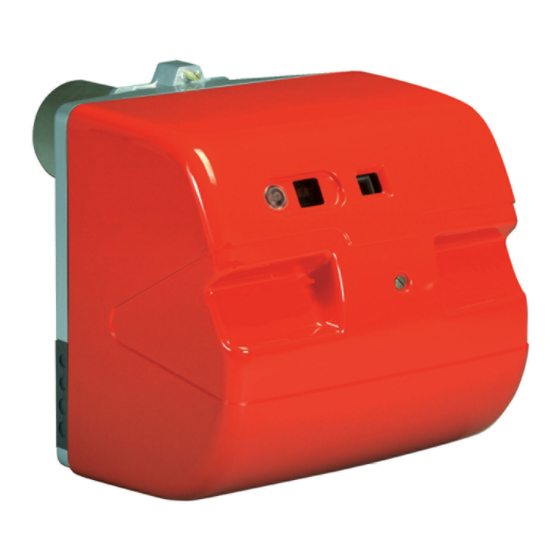
Riello RL 28/M Installation, Use And Maintenance Instructions
Kit for long combustion head
Hide thumbs
Also See for RL 28/M:
Table of Contents
Advertisement
Available languages
Available languages
Quick Links
Advertisement
Chapters
Table of Contents

Summary of Contents for Riello RL 28/M
- Page 1 Istruzioni per installazione, uso e manutenzione Installation, use and maintenance instructions Kit testa lunga Kit for long combustion head CODICE - CODE MODELLO - MODEL 3010120 RL 28/M 3010121 RL 38/M 3010122 RL 50/M 2915445 (2) - 05/2016...
-
Page 3: Table Of Contents
Indice Avvertenze generali ................................... 3 Garanzia e responsabilità............................3 Note sulla sicurezza per l'installazione........................3 Installazione....................................4 Materiale a corredo del kit ............................4 Smontaggio del bruciatore dalla caldaia ........................4 Accessibilità parte interna testa........................... 5 Trasformazione testa di combustione ......................... 5 Posizione elettrodi ............................... -
Page 4: Avvertenze Generali
Avvertenze generali Avvertenze generali Garanzia e responsabilità I diritti alla garanzia ed alla responsabilità decadono, in caso di – Il personale deve usare sempre i mezzi di protezione indivi- danni a persone e/o cose, qualora i danni stessi siano riconduci- duale previsti dalla legislazione e seguire quanto riportato nel bili ad una o più... -
Page 5: Installazione
Installazione Installazione Materiale a corredo del kit Portaugello ........N. 1 Alberino. -
Page 6: Accessibilità Parte Interna Testa
Installazione Accessibilità parte interna testa L’apertura del bruciatore avviene attraverso le due guide di arre- ➤ svitare vite 4) per scollegare l'assieme interfaccia dal resto tramento presenti sulla parte superiore. del bruciatore; Per l’apertura del bruciatore procedere come segue: ➤ far scorrere il corpo del bruciatore lungo le due guide 1) e le ➤... -
Page 7: Posizione Elettrodi
Installazione ➤ Inserire le due prolunghe 19)(Fig. 6) fornite a corredo del kit ➤ inserire le due nuove guarnizioni 14) e il nuovo portaugello nel supporto 17) e fissarle con i due raccordi 18); 15) forniti a corredo del kit; ➤... -
Page 8: Dimensioni D'ingombro
Installazione Dimensioni d’ingombro Il kit permette l’allungamento della testa di combustione di + 110 mm. Modello Ø D RL 28-38/M RL 50/M Tab. A Verificare dopo l’installazione del kit le dimensioni riportate in Fig. 8. ATTENZIONE 20119869 Fig. 8 Chiusura bruciatore Rimontare con procedura inversa a quanto descritto, riposizio- nando tutti i componenti del bruciatore come in origine. -
Page 9: Catalogo Ricambi
Catalogo ricambi Catalogo ricambi 20119619 Fig. 9 COD. DESCRIZIONE • • • 3003795 COLLEGAMENTO ELETTRODO • • • 3003790 PIASTRA • • • 3012096 GRUPPO PORTAUGELLO • • • 3003764 PROLUNGA • 3013903 GRUPPO REGOLATORE • 3013904 GRUPPO REGOLATORE • 3013905 GRUPPO REGOLATORE •... - Page 11 Contents General warnings ..................................10 Guarantee and responsibility............................. 10 Installation safety notes............................. 10 Installation ....................................11 Burner equipment supplied with the kit ........................11 Disassembly of the burner from the boiler......................... 11 Access to head internal part............................12 Conversion of the combustion head.......................... 12 Electrode positions ..............................
-
Page 12: General Warnings
General warnings General warnings Guarantee and responsibility The rights to the guarantee and the responsibility will no longer – Personnel must always use the personal protective equip- be valid in the event of damage to things or injury to people, if ment envisaged by legislation and follow the indications giv- such damage/injury was due to any of the following causes: en in this manual. -
Page 13: Installation
Installation Installation Burner equipment supplied with the kit Nozzle holder ........No. 1 Spindle . -
Page 14: Access To Head Internal Part
Installation Access to head internal part The burner is opened using the two retraction slide bars on the ➤ unscrew the screw 4) to disconnect the interface assembly top part. from the rest of the burner; To open the burner, proceed as follows: ➤... -
Page 15: Electrode Positions
Installation ➤ Insert the two extensions 19)(Fig. 6) supplied with the kit into ➤ insert the two new gaskets 14) and the new nozzle holder the support 17) and fix them with the two couplings 18); 15) supplied in the kit; ➤... -
Page 16: Maximum Dimensions
Installation Maximum dimensions The kit allows the combustion head to be extended by + 110 mm. Model Ø D RL 28-38/M RL 50/M Tab. A After the installation of the kit check the dimen- sions shown in Fig. 8. WARNING 20119869 Fig. -
Page 17: Spare Parts List
Spare parts list Spare parts list 20119619 Fig. 9 No. CODE DESCRIPTION • • • 3003795 ELECTRODE CONNECTION • • • 3003790 PLATE • • • 3012096 NOZZLE-HOLDER ASSEMBLY • • • 3003764 EXTENSION • 3013903 REGULATOR UNIT • 3013904 REGULATOR UNIT •... - Page 20 Con riserva di modifiche - Subject to modifications...


