Table of Contents
Advertisement
INSTALLATION MANUAL
AIR
CONDITIONER
Please read this installation manual completely before installing the product.
Installation work must be performed in accordance with the national wiring standards
by authorized personnel only.
Please retain this installation manual for future reference after reading it thoroughly.
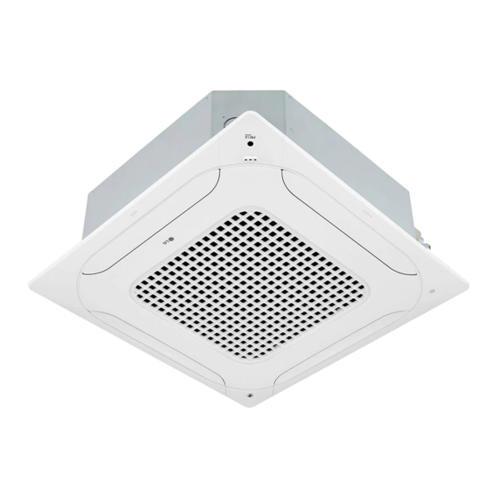
Ceiling Cassette – 4Way
Original instruction
[Representative] LG Electronics Inc. EU Representative : LG Electronics European Shared
Service Center B. V . Krijgsman 1, 1186 DM Amstelveen, The Netherlands
[Manufacturer] LG Electronics Inc. Changwon 2nd factory 84, Wanam-ro, Seongsan-gu,
Changwon-si, Gyeongsangnam-do, KOREA
MFL68686515
Rev.00_041519
Copyright © 2016 - 2019 LG Electronics Inc. All Rights Reserved.
www.lg.com
Advertisement
Table of Contents

Related Manuals for LG ARNU18GTQD4


Summary of Contents for LG ARNU18GTQD4
- Page 1 Please retain this installation manual for future reference after reading it thoroughly. Ceiling Cassette – 4Way Original instruction [Representative] LG Electronics Inc. EU Representative : LG Electronics European Shared Service Center B. V . Krijgsman 1, 1186 DM Amstelveen, The Netherlands [Manufacturer] LG Electronics Inc. Changwon 2nd factory 84, Wanam-ro, Seongsan-gu, Changwon-si, Gyeongsangnam-do, KOREA www.lg.com...
-
Page 2: Table Of Contents
Table of contents TABLE OF CONTENTS INSTALLATION PARTS SAFETY PRECAUTIONS INSTALLATION Selection of the best location Ceiling dimension and hanging bolt location Wiring Connection Installation of Decoration Panel Drain Piping Ceiling Height Selection DIP Switch Setting Group Control Setting Model Designation Airborne Noise Emission Limiting concentration Indoor Unit... -
Page 3: Installation Parts
Installation Parts Installation Parts Anti-bacteria filter Intake Air Outlet Wired Remote Controller(Accessory) Installation Tool Washer for Clamp Insulation for (Other) Clamp metal Name Drain hose hanging backet (Tie Wrap) fitting Quantity 1 EA 2 EA 8 EA 4 EA 1 SET •... -
Page 4: Safety Precautions
Safety Precautions Safety Precautions The following symbols are displayed on indoor and outdoor units. Read the precautions in this manual This appliance is filled with flammable carefully before operating the unit. refrigerant (R32) This symbol indicates that a service This symbol indicates that the Operation personnel should be handling this Manual should be read carefully. - Page 5 Safety Precautions • Do not install, remove, or re-install the unit by yourself (customer). - There is risk of fire, electric shock, explosion, or injury. • Be cautious when unpacking and installing the product. - Sharp edges could cause injury. Be especially careful of the case edges and the fins on the condenser and evaporator.
- Page 6 Safety Precautions • Take care to ensure that power cable could not be pulled out or damaged during operation. - There is risk of fire or electric shock. • Do not place anything on the power cable. - There is risk of fire or electric shock. •...
- Page 7 Safety Precautions • When the product is not be used for a long time, disconnect the power supply plug or turn off the breaker. - There is risk of product damage or failure, or unintended operation. • Take care to ensure that nobody could step on or fall onto the outdoor unit.
- Page 8 Safety Precautions • Any person who is involved with working on or breaking into a refrigerant circuit should hold a current valid certificate from an industry- accredited assessment authority, which authorises their competence to handle refrigerants safely in accordance with an industry recognised assessment specification.
- Page 9 Safety Precautions • Do not insert hands or other objects through the air inlet or outlet while the product is operated. - There are sharp and moving parts that could cause personal injury. • Do not drink the water drained from the product. - It is not sanitary and could cause serious health issues.
-
Page 10: Installation
Installation Installation Read completely, then follow step by step. Selection of the best location • If the temperature might rise above 30 ℃ or the humidity might rise above RH 80 %, attach the Dew-Protective kit or use another insulation to the indoor body. h Dew Protective kit is sold separately. - Page 11 Installation Minimum floor area (for R32) - The appliance shall be installed, operated and stored in a room with a floor area larger than the minimum area. - Use the graph of table to determine the minimum area. Amin (m Floor standing Wall mounted Ceiling mounted...
-
Page 12: Ceiling Dimension And Hanging Bolt Location
Installation Ceiling dimension and hanging bolt location • The dimensions of the paper model for installation are the same as those of the ceiling opening dimensions. Ceiling Ceiling board Level gauge TQ/TR Chassis TM/TN/TP Chassis 585~660(Ceiling opening) 875 (Ceiling opening) 787 (Hanging bolt) 840 Unit size Unit:mm... -
Page 13: Wiring Connection
Installation Ceiling Keep the length of the bolt Hanging bolt 105 mm(TM,TN,TP chassis), from the bracket to 40 mm (W3/8 or M10) 180 mm(TQ,TR chassis) Flat washer for M10 Air Conditioner body (W3/8 or M10) Ceiling board (accessory) Ceiling board Keep the length of 15 mm(TM,TN,TP chassis), 31~34 mm(TQ,TR chassis) between the air conditioner bottom surface and the ceiling surface... - Page 14 Installation • TQ/TR Chassis Terminal Block of outdoor unit Terminal Block Indoor Outdoor SODU INTERNET DRY1 DRY2 GND 12 V Unit 1(L) 2(N) INDOOR POWER INPUT • TM/TN/TP Chassis Terminal Block of outdoor unit Terminal Block Terminal Block Terminal Block Indoor Indoor Indoor...
-
Page 15: Installation Of Decoration Panel
Installation Installation of Decoration Panel The decoration panel has its installation Before installing the decoration panel, direction. always remove the paper template. 1. Temporarily fix two decoration panel fixing screws (hexagon M5 screw) on the unit body. (Tighten by amount 10 mm in length.) The fixing screws (hexagon M5 screw) are included the indoor unit box. -
Page 16: Drain Piping
Installation Drain Piping • Drain piping must have down-slope (1/50 to 1/100): be sure not to Upward provide up-and-down slope to prevent reversal flow. Pipe clamp routing • During drain piping connection, be careful not to exert extra force not allowed on the drain port on the indoor unit. -
Page 17: Ceiling Height Selection
Installation Attention 1. Possible drain-head height is up to 700 mm. So, it must be installed below 700 mm. 2. Keep the drain hose downward up to 1/50~1/100 inclination. 1/50~1/100 Prevent any upward flow or reverse flow in any MAX 700 mm part. -
Page 18: Dip Switch Setting
Installation DIP Switch Setting 1. Indoor Unit Function Description Setting Off Setting On Default Communication N/A (Default) Cycle N/A (Default) Group Control Selection of Master or Slave Master Slave Dry Contact Mode Selection of Dry Contact Wired/Wireless remote Mode controller Auto Selection of Manual or Auto operation Mode... -
Page 19: Group Control Setting
Installation Group Control Setting 1. Group Control 1 n Wired remote controller 1 + Standard Indoor Units LGAP Network System Signal Master Slave Slave Slave 12 V Only connect serial signal and Display Error Message GND lines between indoor units. Master °C/°F(5 s) TIME(3 s) - Page 20 Installation h It is possible to connect indoor units since Feb. 2009. h It can be the cause of malfuctions when there is no setting of master and slave. h In case of Group Control, it is possible to use following functions. - Selection of operation, stop or mode - Temperature setting and room temperature check - Current time change...
- Page 21 Installation 3. Group Control 3 n Mixture connection with indoor units and Fresh Air Intake Unit LGAP Network System Signal Master Slave Master Slave 12 V Display Error Message Display Error Message °C/°F(5 s) TIME(3 s) Master Master h In case of connecting with standard indoor unit and Fresh Air Intake Unit, separate Fresh Air Intake Unit with standard units.
- Page 22 Installation 4. 2 Remote Control n Wired remote controller 2 + Indoor unit 1 LGAP Network System Slave Slave Slave Signal Master 12 V Display Error Message °C/°F(5 s) TIME(3 s) Master Slave 1. It is possible to connect two wired remote controllers (Max.) with one indoor unit. Set only one indoor unit to Master, set the others to Slave.
- Page 23 Installation 5. Accessories for group control setting It is possible to set group control by using below accessories. Indoor unit 2 EA + Wired remote controller 1 EA Indoor unit 1 EA + Wired remote controller 2 EA h PZCWRCG3 cable used for connection h PZCWRC2 cable used for connection Slave Master...
-
Page 24: Model Designation
Installation Model Designation Serial Number Combinations of functions A/B:Basic function L: Neo Plasma(Wall Mounted) C/D: Plasma(Ceiling Cassette) Chassis Name Electrical Ratings 1: 1Ø, 115 V, 60 Hz 2: 1Ø, 220 V, 60 Hz 6: 1Ø, 220 - 240 V, 50 Hz 7: 1Ø, 100 V, 50/60 Hz 3: 1Ø, 208/230 V, 60 Hz G: 1Ø, 220 - 240 V, 50 Hz/1Ø, 220 V, 60 Hz...