Mitsubishi Electric MELSERVO-JET MR-JET-G-N1 Series User Manual
System
Hide thumbs
Also See for MELSERVO-JET MR-JET-G-N1 Series:
- User manual (84 pages) ,
- User manual (124 pages) ,
- User manual (48 pages)

Related Manuals for Mitsubishi Electric MELSERVO-JET MR-JET-G-N1 Series


Summary of Contents for Mitsubishi Electric MELSERVO-JET MR-JET-G-N1 Series
- Page 1 Mitsubishi Electric AC Servo System MR-JET-G-N1 User's Manual (Introduction) -MR-JET-_G-N1...
-
Page 3: Safety Instructions
SAFETY INSTRUCTIONS Please read the instructions carefully before using the equipment. To use the equipment correctly, do not attempt to install, operate, maintain, or inspect the equipment until you have read through this manual, installation guide, and appended documents carefully. Do not use the equipment until you have a full knowledge of the equipment, safety information and instructions. - Page 4 [Installation/wiring] WARNING ● To prevent an electric shock, turn off the power and wait for 15 minutes or more before starting wiring and/or inspection. ● To prevent an electric shock, ground the servo amplifier. ● To prevent an electric shock, any person who is involved in wiring should be fully competent to do the work.
-
Page 5: Disposal Of Waste
Please dispose of this product, battery (primary battery), and other options according to your local laws and regulations. ABOUT THE MANUAL e-Manuals are Mitsubishi Electric FA electronic book manuals that can be browsed with a dedicated tool. e-Manuals enable the following: •... - Page 6 If using the servo for the first time, prepare and use the following related manuals to ensure that the servo is used safely. (1) Introduction This manual is necessary primarily for installing, wiring, and using options. (3) Rotary Servo Motor (2) Hardware (4) Linear Servo Motor (5) Partner Encoder...
-
Page 7: U.s. Customary Units
Interpreting servo parameter numbers For a servo parameter which uses one particular digit to select a function, the position of its digit indicates the detail number of the servo parameter, and the value in hexadecimal which is set to the digit indicates the selected function. For example, the detail number of the servo parameter in the last digit is expressed as [Pr. -
Page 8: Table Of Contents
CONTENTS SAFETY INSTRUCTIONS..............1 DISPOSAL OF WASTE . - Page 9 Inspection items ............... . 43 Periodic inspection .
- Page 10 Motor extension setting servo parameters group ([Pr. PL_ _ ]) ........79 Positioning control setting servo parameters group ([Pr.
-
Page 11: Chapter 1 Specifications
SPECIFICATIONS Outline MR-JET-_G-N1 are EtherCAT servo amplifiers. EtherCAT is an abbreviation of Ethernet for Control Automation Technology. It is open network communication between a master station and slave stations via real-time Ethernet developed by Beckhoff Automation GmbH. Model designation Rating plate The following shows an example of the rating plate for explanation of each item. -
Page 12: Servo Amplifier Standard Specifications
Servo amplifier standard specifications MR-JET-_G-N1 Model: MR-JET-_-N1 100G 200G 300G Output Voltage 3-phase 0 V AC to 240 V AC Rated current [A] 11.0 11.0 Power supply input Voltage/Frequency 3-phase or 1-phase 200 V AC to 240 V AC, 50 Hz/60 Hz 3-phase or 1-phase 200 V 3-phase 200 AC to 240 V AC, 50 Hz/60... -
Page 13: Environment
Environment Item Operation Transportation Storage Ambient 0 ˚C to 55 ˚C (non-freezing) -25 ˚C to 70 ˚C (non-freezing) -25 ˚C to 70 ˚C (non-freezing) temperature Class 3K3 (IEC 60721-3-3) Class 2K12 (IEC 60721-3-2) Class 1K4 (IEC 60721-3-1) Ambient humidity 5 %RH to 95 %RH (non-condensing) 5 %RH to 95 %RH (non-condensing) 5 %RH to 95 %RH (non-condensing) Ambience... -
Page 14: Function Block Diagram
Function block diagram The following shows the function block diagram of this servo amplifier. Regenerative option Servo amplifier Servo motor Diode Dynamic brake stack Relay circuit MCCB Power Current supply detector Regenerative Charge light Cooling fan 24 V DC Electromagnetic brake Control circuit... -
Page 15: Configuration Including Peripheral Equipment
Configuration including peripheral equipment • To prevent a malfunction, do not connect these connectors to any network other than the specified network. • Equipment other than the servo amplifier and servo motor is optional or a recommended product. The following is an example using MR-JET-40G-N1. R S T Junction terminal block Power... -
Page 16: Chapter 2 Function
FUNCTION Function restrictions Category Detailed functions Network communication cycle restrictions (minimum) Control mode Profile position mode (pp) 250 μs Profile velocity mode (pv) 250 μs Profile torque mode (tq) 250 μs Function list The function list of this servo amplifier is shown in the following table. For details of the functions, refer to each section indicated in the detailed explanation field. - Page 17 Position detection Functions Detailed functions Description Firmware Detailed explanation version Control method Semi closed loop system This function uses the servo motor encoder to configure semi closed loop systems. Absolute Absolute position detection This function performs homing once, and thereafter Refer to "ABSOLUTE position system...
- Page 18 Control function Functions Detailed functions Description Firmware Detailed explanation version Vibration Advanced vibration This function suppresses vibration and residual Refer to "Advanced vibration suppression suppression control II vibration at an arm end. suppression control II" in the following manual. MR-JET User's Manual (Adjustment) Machine resonance This function decreases the gain of the specific...
- Page 19 Adjustment function Functions Detailed functions Description Firmware Detailed explanation version Automatic Quick tuning This function automatically adjusts the gain at servo- Refer to "Quick tuning" in the adjustment on in a short time without acceleration/deceleration following manual. MR-JET User's Manual operation of the servo motor.
- Page 20 Option Functions Detailed functions Description Firmware Detailed explanation version Regenerative Regenerative option Use this function if the built-in regenerative resistor Refer to "Regenerative option" capacity of the servo amplifier does not have sufficient in the following manual. enhancement regenerative capacity for the generated regenerative MR-JET User's Manual power.
-
Page 21: Security
(Function) Security To completely prevent unauthorized access to the system from external devices, the user also must take safety measures. Mitsubishi Electric Corporation cannot be held responsible for any problems caused by unauthorized access. 2 FUNCTION 2.2 Security... -
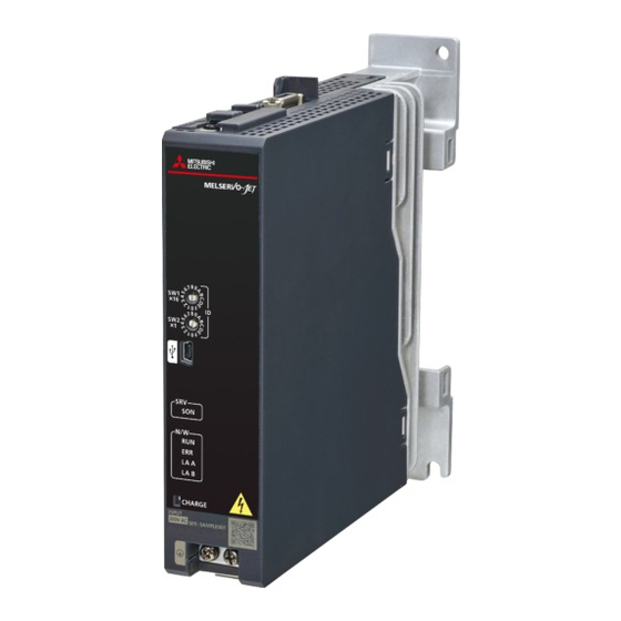
Page 22: Chapter 3 Structure
STRUCTURE Parts identification MR-JET-_G-N1 The diagram shows the MR-JET-40G-N1 servo amplifier. Front Right side (12) Side (13) (10) (11) Bottom *1 Servo amplifiers are shipped from the factory with a protective sticker on the front. 3 STRUCTURE 3.1 Parts identification... - Page 23 Name Application Detailed explanation Display section The 1-digit, 7-segment LED display shows the servo status and Page 22 Switch setting and alarm number. display of the servo amplifier Network status LEDs Displays each network status. ID setting switches (SW1/SW2) Set the node address of the servo amplifier. ...
-
Page 24: Switch Setting And Display Of The Servo Amplifier
Switch setting and display of the servo amplifier Network settings can be configured using switches on the servo amplifier. The network communication status and alarm status can also be checked on the display (1-digit, 7-segment LED) of the servo amplifier. Switches If a metal screw driver contacts with the conductive areas, the switches may malfunction. -
Page 25: 7-Segment Led
7-segment LED The network connection status, servo status, and alarm/warning occurrence statuses can be checked on the 7 segment LED display. Display sequence The following shows the display sequence of the 7-segment LED display after power-on. Once a system check is complete and the servo amplifier is started, the network connection status will be displayed. - Page 26 When the network is not connected The 7-segment LED display during initialization is as follows. Display Description Indicates that the servo amplifier is not connected to the controller. Indicates the Pre-Operational state shown in the state transition diagram of the ESM state machine. Indicates the Safe-Operational state shown in the state transition diagram of the ESM state machine.
-
Page 27: Status Leds
Status LEDs The servo status LED shows the servo status. The network status LEDs show the network status. Servo status LED Network status LEDs Servo status LED Description Off: Indicates ready-off and servo-off status. (green) Blinking: Indicates ready-on and servo-off status. On: Indicates ready-on and servo-on status. -
Page 28: Led Display
LED display RUN (RUN LED), ERR (ERROR LED), LA A (Link/Activity), and LA B (Link/Activity) operate in accordance with the EtherCAT standard (ETG.1300 EtherCAT Indicator and Labeling Specification). LED status definitions The following shows LED status definitions. LED status Definition The LED is lit steady. -
Page 29: Chapter 4 Startup
STARTUP • MR-JET-_G-N1 servo amplifiers can only be set with MR Configurator2 version 1.105K or later. • This chapter explains how to start up the servo amplifier by using MR Configurator2 with software version 1.100E. • Before starting operation, check each servo parameter. Depending on the machine, an unexpected operation may occur. - Page 30 Start MR Configurator2 and create a new project. For the connection setting, select USB. Select the servo amplifier model. Selecting "Parameter" from the project tree opens the "Parameter Setting" screen. 4 STARTUP...
- Page 31 Select a group of servo parameters in the selection tree of the "Parameter Setting" window to display and configure the settings. After changing the servo parameter, click "Selected Items Write" or "Axis Writing". 4 STARTUP...
- Page 32 Abbreviated servo parameters prefixed with * and servo parameters marked with ** are enabled after the power is cycled or a software reset is performed. Click "Software Reset" in MR Configurator2 to perform the software reset. 4 STARTUP...
-
Page 33: Turning On Servo Amplifier For The First Time
Turning on servo amplifier for the first time • For the controller settings, refer to the relevant controller manual. • For the gain adjustment, refer to the following. MR-JET User's Manual (Adjustment) When turning on the servo amplifier for the first time, follow the steps below. Procedure Description Reference... -
Page 34: Test Operation Of The Servo Motor Alone In Test Operation Mode
Test operation of the servo motor alone in test operation mode • If the servo motor operates in an unintended manner, stop the servo motor with EM2 (Forced stop 2). Check that the servo amplifier and servo motor operate normally. With the servo motor disconnected from the machine, use the test operation mode and check whether the servo motor operates correctly. -
Page 35: Equipment Configuration Setting
Equipment configuration setting Set the servo parameters for each function according to the equipment configuration. Refer to the following for details. MR-JET User's Manual (Function) Item Description Rotation/travel direction selection To change the rotation/travel direction (POL), change the servo parameter. Stroke limit function Limit switches can be used to limit travel intervals of the servo motor. -
Page 36: Operation By Controller Command
Operation by controller command Confirm that the servo motor operates correctly under the commands from the controller. Give a low speed command at first to check the servo motor operations such as the rotation direction. If the servo motor does not operate in the intended direction, check the input signal. -
Page 37: Instructions On Startup
Instructions on startup Instructions for power-on • When the absolute position detection system is used in a rotary servo motor, [AL. 025 Absolute position erased] occurs the first time that the power is turned on and the servo motor cannot be changed to servo-on status. Shut off the power once, then cycle the power to deactivate the alarm. -
Page 38: Duplicate Setting
Duplicate setting Servo amplifier parameters for which setting has been completed can be copied to another servo amplifier. Use this function when replacing the servo amplifier of equipment with another servo amplifier during operation, and when starting up multiple devices with the same configuration. Restrictions ■The following data is not duplicated. -
Page 39: Test Operation Mode
Test operation mode Setting the servo amplifier to the test operation mode enables the test operation while the personal computer and servo amplifier are connected via a USB cable. Set [Pr. PC05.1 Test operation selection] to "1" (enabled). Cycle the power of the servo amplifier. Once initialization is complete, the display will change as follows. Test operation status display Use MR Configurator2 to perform the test operation. - Page 40 Positioning operation Positioning operation can be performed without the controller. Operate the motor using the Positioning Mode screen of MR Configurator2. ■Motor operation setting (1) Set the motor speed, acceleration/deceleration time constants, and travel distance in the positioning operation mode. When changing the speed to the permissible speed, set the speed in [Pr.
- Page 41 Program operation Positioning operation using multiple operation patterns can be performed without a controller. Operate the motor using the Program Operation screen of MR Configurator2. For details, refer to Help of MR Configurator2. Open the Program Operation screen of MR Configurator2. Item Screen operation Program display...
-
Page 42: Motor-Less Operation
Motor-less operation The motor-less operation cannot be used in the linear servo motor control mode. Without connecting a servo motor to the servo amplifier, output signals or status displays can be provided in response to the controller commands as if the servo motor is actually running. This operation can be used to check the sequence of a controller. -
Page 43: Output Signal (Do) Forced Output
Output signal (DO) forced output This function forcibly switches the output signals on and off regardless of the servo status. Use this function for purposes such as checking output signal wiring. Operate this function on the DO Forced Output screen of MR Configurator2. Each output signal can be turned on/off by clicking the ON/OFF button next to its name. -
Page 44: Servo Amplifier Setting Initialization
Servo amplifier setting initialization Servo amplifier settings can be initialized by using the engineering tool (MR Mode Change packed with MR Configurator2). However, information related to the servo amplifier, including power-on cumulative time and the number of relays on/off, is not initialized. -
Page 45: Chapter 5 Maintenance, Inspection And Parts Replacement
MAINTENANCE, INSPECTION AND PARTS REPLACEMENT Inspection items Precautions • Do not disassemble, repair, or modify the product. • For repair and parts replacement, contact your local sales office. • To prevent a malfunction, do not perform an insulation resistance test (megger test) on the servo amplifier. Periodic inspection Perform the following inspections. - Page 46 Servo amplifier cooling fan The cooling fan bearings will reach the end of their service life in 50,000 hours to 70,000 hours. Therefore, the cooling fan must be replaced after seven to eight years of continuous operation as a guideline. If unusual noise or vibration is found during inspection, the cooling fan must also be replaced.
-
Page 47: Replacing Fan Unit
Replacing fan unit The internal circuits of the servo amplifier may be damaged by static electricity. Take the following precautions. • Ensure that the work bench and your body are grounded. • Do not directly touch conductive areas such as the connector pins and electrical parts. The fan unit is composed of a cooling fan and its cover. -
Page 48: Chapter 6 Compliance With Global Standards
COMPLIANCE WITH GLOBAL STANDARDS Compliance with global standards Refer to the following manual for information about compliance with global standards. Safety Instructions and Precautions for MR-JET AC Servos (IB(NA)-0300492chn) Handling of AC servo amplifier batteries for the United Nations Recommendations on the Transport of Dangerous Goods Rev. - Page 49 ■Transportation of lithium metal batteries alone Packaging requirements Classification Main requirements UN3090 PI968 Section Eight cells or fewer per package with one gram or less of lithium The package must pass a 1.2 m drop test, and a handling label with a battery illustration (size: 120 ...
- Page 50 ■Transportation precaution for customers For sea or air transportation, the handling label (above Fig.) must be attached to the package of a Mitsubishi Electric cell or battery. In addition, attaching the label to the outer package of an overpack containing several packages by Mitsubishi Electric is also required.
-
Page 51: Symbol For The New Eu Battery Directive
• This mark is valid only in EU. This mark is in accordance with directive 2006/66/EC Article 20 "Information for end-users" and Annex . MITSUBISHI ELECTRIC products are designed and manufactured with high quality materials and components which can be recycled and/or reused. -
Page 52: Compliance With China Compulsory Certification (Ccc)
Some products are required to comply with China Compulsory Certification (hereinafter referred to as CCC) if exported, distributed, or sold to China. An outline of CCC is explained in this section. Mitsubishi Electric servo products are not subject to CCC. -
Page 53: Compliance With The China Rohs Directive
Compliance with the China RoHS directive Outline The China RoHS directive: (Management Methods for Controlling Pollution by Electronic 电子信息产品污染控制管理办法 Information Products) came into effect on March 1, 2007. The China RoHS directive was replaced by the following China RoHS directive: 电器电子产品有害物质限制使用管理办法... - Page 54 • Lead as an alloying element in steel for machining purposes and in galvanized steel containing up to 0.35 % lead by weight, lead as an alloying element in aluminum containing up to 0.4 % lead by weight, and copper alloy containing up to 4 % lead by weight, e.g.
-
Page 55: Chapter 7 Servo Parameters
SERVO PARAMETERS Refer to the following manual for the parameters not described in this chapter. MR-JET-G User's Manual (Parameters) Extension setting servo parameters group ([Pr. PC_ _ ]) [Pr. PC42_Function selection C-10 (COP10)] Initial value Setting range Ver. 00000000h Refer to the relevant detail No. Refer to the relevant detail No. -
Page 56: [Pr. Pc44_Reverse Rotation Torque Limit 2 (Tln2)]
[Pr. PC44_Reverse rotation torque limit 2 (TLN2)] Initial value Setting range Ver. 1000.0 [%] 0.0 to 1000.0 The torque or thrust generated by the servo motor can be limited. Set this servo parameter in relation to the rated torque or continuous thrust (= 100.0 %). Set the servo parameter to limit the torque of the servo motor for CW power running or CCW regeneration, or to limit the thrust of the linear servo motor for positive direction power running or negative direction regeneration. -
Page 57: [Pr. Pc73_Speed Reached 2 - Output Filtering Time (Sa2F)]
[Pr. PC73_Speed reached 2 - Output filtering time (SA2F)] Initial value Setting range Ver. 0 [ms] 0 to 65535 This servo parameter sets the time until the speed reached 2 output turns on. If the state where the error between the speed command and the servo motor speed is within [Pr. PC72 Speed reached 2 - Output range] continues for the setting value of this servo parameter or longer, bit 10 (Target velocity reached) of [Statusword (Obj. -
Page 58: Extension Setting 2 Servo Parameters Group ([Pr. Pe
Extension setting 2 servo parameters group ([Pr. PE_ _ ]) [Pr. PE53_Maximum torque limit 1 (TLMX1)] Initial value Setting range Ver. 1000.0 [%] 0.0 to 1000.0 The torque or thrust generated by the servo motor can be limited. When [Pr. PC78.1 Maximum torque limit 1 selection] is set to "0" (the maximum torque limit 1 is disabled) The torque limit function using this servo parameter or [Max torque (Obj. -
Page 59: Positioning Control Setting Servo Parameters Group ([Pr. Pt
Positioning control setting servo parameters group ([Pr. PT_ _ ]) [Pr. PT01_Command mode selection (**CTY)] Initial value Setting range Ver. 00000300h Refer to the relevant detail No. Refer to the relevant detail No. [Pr. PT01.1_Speed/acceleration/deceleration unit selection] Initial value Setting range Ver. -
Page 60: Network Setting Servo Parameters Group ([Pr. Pn
Network setting servo parameters group ([Pr. PN_ _ ]) [Pr. PN02_For manufacturer setting] This servo parameter is for manufacturer setting. [Pr. PN05_For manufacturer setting] This servo parameter is for manufacturer setting. [Pr. PN18_Counter level for communication error detection (CERN)] Initial value Setting range Ver. -
Page 61: Lists Of Supported Control Modes
Lists of supported control modes The following shows the meaning of each abbreviation used in the lists. "" indicates the modes that can be used, and "" indicates the modes that cannot be used or modes that are not used even if set. Mode List abbreviation Meaning... -
Page 62: Gain/Filter Setting Servo Parameters Group ([Pr. Pb
Gain/filter setting servo parameters group ([Pr. PB_ _ ]) Detail No. Operation mode Control mode Standard Linear PB01 PB01.0 PB01.3 ... - Page 63 Detail No. Operation mode Control mode Standard Linear PB45 PB45.0-1 PB45.2 PB46 ...
-
Page 64: Extension Setting Servo Parameters Group ([Pr. Pc
Extension setting servo parameters group ([Pr. PC_ _ ]) Detail No. Operation mode Control mode Standard Linear PC01 PC02 ... -
Page 65: I/O Setting Servo Parameters Group ([Pr. Pd
I/O setting servo parameters group ([Pr. PD_ _ ]) Detail No. Operation mode Control mode Standard Linear PD01 PD01.0-7 PD03 PD03.0-1 PD04 PD04.0-1 ... -
Page 66: Extension Setting 3 Servo Parameters Group ([Pr. Pf
Extension setting 3 servo parameters group ([Pr. PF_ _ ]) Detail No. Operation mode Control mode Standard Linear PF02 PF02.4 PF02.5 ... -
Page 67: Motor Extension Setting Servo Parameters Group ([Pr. Pl
Motor extension setting servo parameters group ([Pr. PL_ _ ]) Detail No. Operation mode Control mode Standard Linear PL01 PL01.0 PL01.2 PL02 ... -
Page 68: Positioning Control Setting Servo Parameters Group ([Pr. Pt
Positioning control setting servo parameters group ([Pr. PT_ _ ]) Detail No. Operation mode Control mode Standard Linear PT01 PT01.1 PT02 PT02.7 ... -
Page 69: Positioning Extension Setting Servo Parameters Group ([Pr. Pv
Positioning extension setting servo parameters group ([Pr. PV_ _ Detail No. Operation mode Control mode Standard Linear PV01 PV03 PV05 ... -
Page 70: Lists Of Servo Parameter Initial Values
Lists of servo parameter initial values Basic setting servo parameters group ([Pr. PA_ _ ]) Initial value Remark PA01 00003000h PA02 00000000h PA03 00000000h PA04 00002000h PA05 10000 For manufacturer setting PA06 PA07 PA08 00000001h PA09... -
Page 71: Gain/Filter Setting Servo Parameters Group ([Pr. Pb
Gain/filter setting servo parameters group ([Pr. PB_ _ ]) Initial value Remark PB01 00000000h PB02 00000000h PB03 36000 PB04 PB05 For manufacturer setting PB06 7.00 PB07 15.0 PB08 37.0 PB09 PB10 33.7 ... - Page 72 Initial value Remark PB52 100.0 PB53 100.0 PB54 0.00 PB55 0.00 PB56 PB57 PB58 0.00 PB59 0.00 PB60 PB61 For manufacturer setting PB62 00000000h For manufacturer setting PB63 00000000h For manufacturer setting PB64 00000000h For manufacturer setting...
-
Page 73: Extension Setting Servo Parameters Group ([Pr. Pc
Extension setting servo parameters group ([Pr. PC_ _ ]) Initial value Remark PC01 PC02 PC03 00000000h PC04 00000000h PC05 00000000h PC06 00000000h PC07 PC08 PC09 00000000h For manufacturer setting PC10 00000001h For manufacturer setting PC11 For manufacturer setting PC12... - Page 74 Initial value Remark PC52 00000000h For manufacturer setting PC53 00000000h For manufacturer setting PC54 00000000h For manufacturer setting PC55 00000000h For manufacturer setting PC56 00000000h For manufacturer setting PC57 00000000h For manufacturer setting PC58 00000000h For manufacturer setting PC59 00000000h For manufacturer setting PC60 00000000h...
-
Page 75: I/O Setting Servo Parameters Group ([Pr. Pd
I/O setting servo parameters group ([Pr. PD_ _ ]) Initial value Remark PD01 00000000h PD02 00000000h For manufacturer setting PD03 0000000Ah PD04 0000000Bh PD05 00000022h PD06 00000000h For manufacturer setting PD07 00000005h PD08 00000004h ... - Page 76 Initial value Remark PD52 00000000h For manufacturer setting PD53 00000000h For manufacturer setting PD54 00000000h For manufacturer setting PD55 00000000h For manufacturer setting PD56 00000000h For manufacturer setting PD57 00000000h For manufacturer setting PD58 00000000h For manufacturer setting PD59 00000000h For manufacturer setting ...
-
Page 77: Extension Setting 2 Servo Parameters Group ([Pr. Pe
Extension setting 2 servo parameters group ([Pr. PE_ _ ]) Initial value Remark PE01 00000000h For manufacturer setting PE02 00000000h For manufacturer setting PE03 00000003h For manufacturer setting PE04 For manufacturer setting PE05 For manufacturer setting PE06 For manufacturer setting PE07 For manufacturer setting PE08... - Page 78 Initial value Remark PE52 00000000h For manufacturer setting PE53 1000.0 PE54 00000000h For manufacturer setting PE55 00000000h For manufacturer setting PE56 00000000h For manufacturer setting PE57 00000000h For manufacturer setting PE58 00000000h For manufacturer setting PE59 00000000h For manufacturer setting PE60 00000000h For manufacturer setting...
-
Page 79: Extension Setting 3 Servo Parameters Group ([Pr. Pf
Extension setting 3 servo parameters group ([Pr. PF_ _ ]) Initial value Remark PF01 00000000h For manufacturer setting PF02 00000000h PF03 00000000h For manufacturer setting PF04 For manufacturer setting PF05 00000000h For manufacturer setting PF06 00000013h PF07 00000000h For manufacturer setting PF08 00000000h... - Page 80 Initial value Remark PF52 00000000h For manufacturer setting PF53 For manufacturer setting PF54 For manufacturer setting PF55 For manufacturer setting PF56 For manufacturer setting PF57 00000000h For manufacturer setting PF58 00000000h For manufacturer setting PF59 00000000h For manufacturer setting PF60 00000000h For manufacturer setting PF61...
- Page 81 Motor extension setting servo parameters group ([Pr. PL_ _ ]) Initial value Remark PL01 00000301h PL02 1000 PL03 1000 PL04 00000003h PL05 PL06 PL07 PL08 00001010h PL09 PL10 For manufacturer setting PL11 For manufacturer setting PL12...
- Page 82 Initial value Remark PL52 For manufacturer setting PL53 For manufacturer setting PL54 00000000h For manufacturer setting PL55 00000000h For manufacturer setting PL56 00000000h For manufacturer setting PL57 00000000h For manufacturer setting PL58 00000000h For manufacturer setting PL59 00000000h For manufacturer setting PL60 00000000h For manufacturer setting...
- Page 83 Positioning control setting servo parameters group ([Pr. PT_ _ ]) Initial value Remark PT01 00000310h PT02 00000001h PT03 00000000h For manufacturer setting PT04 00000000h For manufacturer setting PT05 100.00 PT06 10.00 PT07 PT08 PT09 1000 PT10...
- Page 84 Initial value Remark PT52 For manufacturer setting PT53 100.0 PT54 For manufacturer setting PT55 00000000h PT56 PT57 PT58 100.00 For manufacturer setting PT59 500.00 For manufacturer setting PT60 1000.00 For manufacturer setting PT61 200.00 For manufacturer setting PT62 00000000h For manufacturer setting...
- Page 85 Network setting servo parameters group ([Pr. PN_ _ ]) Initial value Remark PN01 00000000h For manufacturer setting PN02 For manufacturer setting PN03 00000000h For manufacturer setting PN04 For manufacturer setting PN05 For manufacturer setting PN06 00000000h For manufacturer setting PN07 00000000h For manufacturer setting PN08...
- Page 86 Positioning extension setting servo parameters group ([Pr. PV_ _ Initial value Remark PV01 PV02 For manufacturer setting PV03 2147483647 PV04 For manufacturer setting PV05 PV06 For manufacturer setting PV07 PV08 For manufacturer setting PV09 PV10 For manufacturer setting PV11 500000...
- Page 87 NETWORK PARAMETERS Refer to the following manual for the parameters not described in this chapter. MR-JET-G User's Manual (Parameters) Network basic parameters [Pr. NPA01_For manufacturer setting] This servo parameter is for manufacturer setting. [Pr. NPA02_For manufacturer setting] This servo parameter is for manufacturer setting. [Pr.
- Page 88 User authentication parameters [Pr. NPB01_For manufacturer setting] This network parameter is for manufacturer setting. [Pr. NPB04_For manufacturer setting] This network parameter is for manufacturer setting. [Pr. NPB05_For manufacturer setting] This network parameter is for manufacturer setting. [Pr. NPB06_For manufacturer setting] This network parameter is for manufacturer setting.
- Page 89 [Pr. NPB17_For manufacturer setting] This network parameter is for manufacturer setting. [Pr. NPB18_For manufacturer setting] This network parameter is for manufacturer setting. [Pr. NPB19_For manufacturer setting] This network parameter is for manufacturer setting. [Pr. NPB20_For manufacturer setting] This network parameter is for manufacturer setting. [Pr.
- Page 90 Section 1.3, Section 6.4, Section 8.2 This manual confers no industrial property rights or any rights of any other kind, nor does it confer any patent licenses. Mitsubishi Electric Corporation cannot be held responsible for any problems involving industrial property rights which may occur as a result of using the contents noted in this manual.
- Page 91 WARRANTY Warranty 1. Warranty period and coverage We will repair any failure or defect hereinafter referred to as "failure" in our FA equipment hereinafter referred to as the "Product" arisen during warranty period at no charge due to causes for which we are responsible through the distributor from which you purchased the Product or our service provider.
- Page 92 TRADEMARKS MELSERVO is a trademark or registered trademark of Mitsubishi Electric Corporation in Japan and/or other countries. EtherCAT is a registered trademark and patented technology licensed by Beckhoff Automation GmbH, Germany. All other product names and company names are trademarks or registered trademarks of their respective companies.
- Page 94 IB(NA)-0300495ENG-B(2007)MEE MODEL: MODEL CODE: HEAD OFFICE : TOKYO BUILDING, 2-7-3 MARUNOUCHI, CHIYODA-KU, TOKYO 100-8310, JAPAN NAGOYA WORKS : 1-14 , YADA-MINAMI 5-CHOME , HIGASHI-KU, NAGOYA , JAPAN When exported from Japan, this manual does not require application to the Ministry of Economy, Trade and Industry for service transaction permission. Specifications are subject to change without notice.