Table of Contents
Advertisement
Controller Kit Installation Manual
MIFH1, MRCH1, MCCH1, MOS1
Installation guide for:
• Wireless Receiver and Cable (MIFH1)
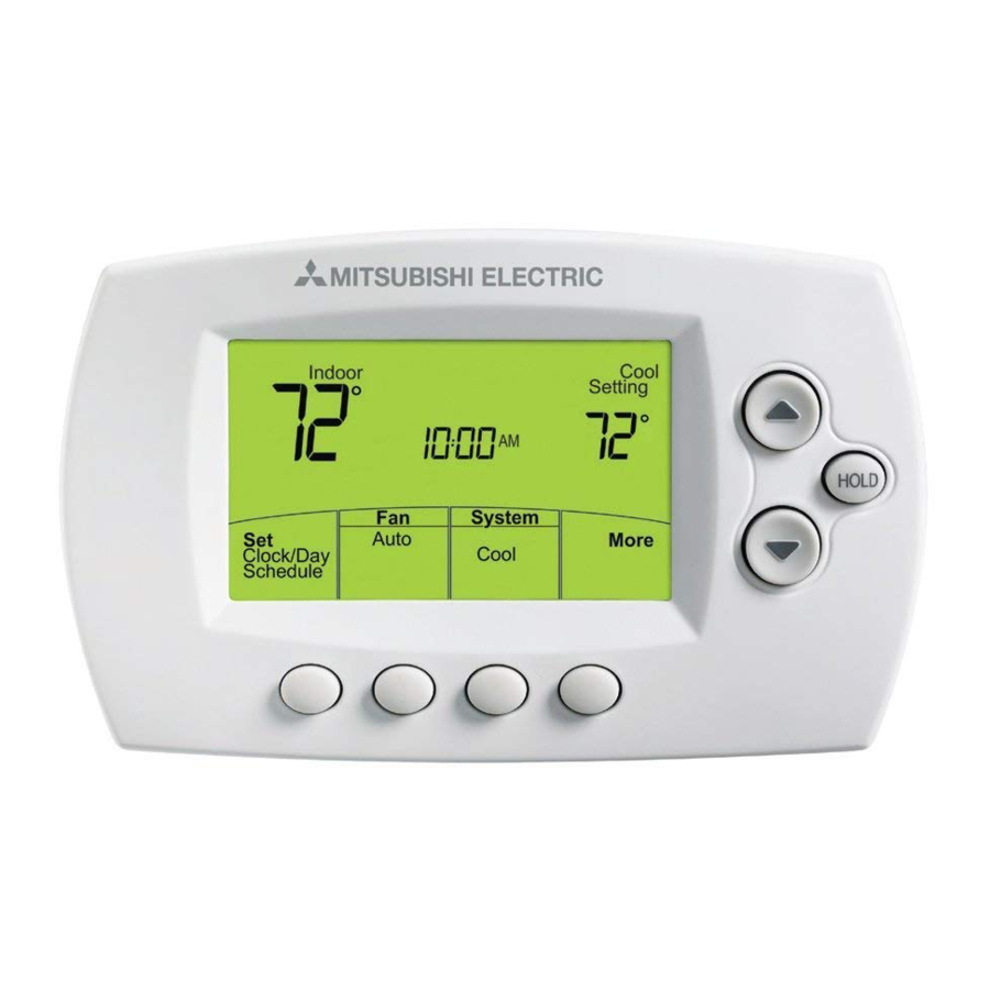
• Remote Controller (MRCH1)
DISCONNECT POWER
electrical shock or equipment damage.
Must be installed by a trained, experienced technician. Read these
instructions carefully. Failure to follow these instructions can damage the product or
cause a hazardous condition.
Installation at a glance
Remote controller
Wireless
outdoor
air sensor
Before you begin, you must attach the cable to the CN105 connector on the indoor unit
control board, then follow the steps in this document.
Remote controllers are linked to specific indoor units. Each indoor unit must have a
dedicated remote controller and wireless receiver.
© 2010 Mitsubishi Electric & Electronics USA, Inc.
Suwanee, GA 30024 All Rights Reserved.
The three diamond logo is a registered trademark
of Mitsubishi Electric Corporation
www.mitsubishipro.com
BEFORE BEGINNING INSTALLATION. Can cause
Wireless receiver
Portable
central
controller
• Portable Central Controller (MCCH1)
• Outdoor Air Sensor (MOS1)
This document covers linking and
installation procedures for the
Mitsubishi Split-Zoning Ductless
and Ducted Systems' RedLINK™
control devices and accessories.
M32309
69-2426-01
Advertisement
Table of Contents

Related Manuals for Mitsubishi Electric MIFH1


Summary of Contents for Mitsubishi Electric MIFH1
- Page 1 Remote controllers are linked to specific indoor units. Each indoor unit must have a dedicated remote controller and wireless receiver. © 2010 Mitsubishi Electric & Electronics USA, Inc. Suwanee, GA 30024 All Rights Reserved. The three diamond logo is a registered trademark of Mitsubishi Electric Corporation www.mitsubishipro.com...
-
Page 2: Install Batteries In Wireless Devices
Wireless System Installation Guide Install batteries in wireless devices Install batteries in all devices. Make sure batteries are inserted properly (see polarity marks on the devices). Remote Controller Install 2 fresh AA batteries Install quick reference card M28472A M28474 Portable Central Controller (optional): Install 3 fresh AA batteries Outdoor air sensor (optional): Install 2 fresh AA lithium batteries Install cable and receiver... -
Page 3: Link All Devices To Wireless Network
Link all devices to wireless network 1 Remove cover from wireless receiver. 2 Verify POWER light is solid green. 3 Press and release the CONNECT button. 4 If CONNECT light does not flash, another receiver or RedLINK wireless adapter may be in wireless setup mode. Exit wireless setup at the other device. POWER LED CONNECT LED Solid Green: Powered and communication Flashing Green: In wireless setup is established. - Page 4 Wireless System Installation Guide Link Portable Central Controller to RedLINK™ network (optional) 1 Make sure the CONNECT light on the wireless receiver is flashing. 2 Press CONNECT at the Portable Central CONNECT Controller. There will be a short delay as the Portable Central Controller seeks a signal from the wireless network. WIRELESS SETUP 3 When the screen displays "Connected," press DONE. M28481 4 Press NO at the next screen to save and exit.
-
Page 5: Exit Wireless Setup
Exit wireless setup Press and release the CONNECT button at the wireless receiver to exit wireless setup (light should stop flashing and remain solid). Replace cover on wireless receiver. Note: The wireless receiver will automatically exit wireless setup after 15 minutes of inactivity. Note: If installing more than one receiver, you must exit wireless setup before installing remote controller and additional receiver. Customize remote controller (installer setup) Follow the steps below to begin installer setup. At each function screen, press s or t to change the setting as desired, then press NEXT to advance to the next function screen. See tables on pages 6-8 for a description of options for each function. To begin, press and hold the FAN and buttons until the display changes. "WAIT"... -
Page 6: Installer Setup Tables
Wireless System Installation Guide Installer setup tables Default settings for Setup functions 101-128 are automatically determined by the HVAC equipment. It may take up to 40 seconds to enter setup, and 30 seconds to exit setup. Setup function Settings & options (factory default in bold) Unit automatically restarts after power outage Not Supported Ventilation Air Not Supported IDU does not intake outdoor air through LOSSNAY IDU does intake outdoor air through LOSSNAY Power Voltage 230V 208V Not Supported Auto energy-savings operation Not Supported Change Filter Duration... - Page 7 Installer setup tables Setup function Settings & options (factory default in bold) Central Controller Not Installed (AG-150 or similar) Installed Present Residential/Commercial Commercial Residential Permanent Hold Lock OFF (Programmable) (Non-programmable) ON (Non-programmable) Fahrenheit/Celsius Fahrenheit Display Celsius Commercial Override 3 Hours Duration 1–12 1–12 Hours System Type...
- Page 8 Wireless System Installation Guide Installer setup tables Setup function Settings & options (factory default in bold) Outdoor Temperature 0 °F (0 °C) Display Offset -5 to 5 °F (-2.5 to 2.5 °C) Outdoor Humidity Display Offset -15% -10% Zone Name THERMOSTAT MASTER BED BASEMENT MEDIA ROOM BATHROOM MUSIC ROOM BATHROOM 1 NURSERY BATHROOM 2...
-
Page 9: Special Functions
Special functions Commercial Override (Setup Function 140): Allows an employee during an unoccupied period to temporarily activate an occupied temperature. Each press of HOLD extends the occupied temperature out 1 hour (or as installed). Optimal Start (Setup Function 150): Allows the remote controller to “learn” how long the equipment will take to reach programmed temperature settings, so the temperature is reached at the scheduled time. Scheduled Off (Setup Function 152): Allows the user to schedule a period where the split-zoning system is completely off and resumes operation at the next scheduled period. Power Off Timer (Setup Function 154): Allows user to schedule indoor unit completely off for one instance: Follow Schedule Option: indoor unit will resume operation at the next scheduled period. -
Page 10: Outdoor Sensor (Optional)
Wireless System Installation Guide Mount remote controller & outdoor sensor 1 Separate the wallplate from the remote controller. 2 Mount the wallplate using the included screws and anchors 5 feet from the floor on an interior wall. If the remote controller is configured to sense indoor temperature, mount in the same room as the indoor unit. -
Page 11: Replacing System Components
Replacing system components Note: Only use Mitsubishi Electric components or other designated components for installation. Failure to comply may damage the product or cause a hazardous condition. Remote Controller To replace a remote controller, install batteries and follow the procedures on page 3 to link it to the wireless network. If necessary, modify settings as needed (see tables on pages 6–8). Portable Central Controller & outdoor sensor To replace a Portable Central Controller or outdoor air sensor, install batteries and follow the procedures on page 4 to link it to the wireless network. Wireless receiver After installing a new wireless receiver, you must re-set the remote controller and Portable Central Controller to communicate with the new equipment, as described... -
Page 12: Regulatory Information
Wireless receiver: 6-7/16 x 3-1/4 x 1-5/16 inches (164 x 82.5 x 34 mm) Outdoor air sensor: 5 x 3-1/2 x 1-11/16 inches (127 x 89 x 43 mm) Portable Central Controller: 6-1/4 x 3-1/8 x 1-5/8 inches (158.2 x 79.9 x 42 mm) © 2010 Mitsubishi Electric & Electronics USA, Inc. Suwanee, GA 30024 All Rights Reserved. The three diamond logo is a registered trademark of Mitsubishi Electric Corporation 69-2426—01 M.S. 11-10 Printed in U.S.A.