Table of Contents
Advertisement
Quick Links
Advertisement
Table of Contents

Related Manuals for YASKAWA VIPA System 300S


Summary of Contents for YASKAWA VIPA System 300S
- Page 1 VIPA System 300S IM | 353-1DP01 | Manual HB140E_IM | RE_353-1DP01 | Rev. 14/47...
- Page 2 Copyright © VIPA GmbH. All Rights Reserved. This document contains proprietary information of VIPA and is not to be disclosed or used except in accordance with applicable agreements. This material is protected by the copyright laws. It may not be reproduced, distributed, or altered in any fashion by any entity (either internal or external to VIPA), except in accordance with applicable agreements, contracts or licensing, without the express written consent of VIPA and the business management owner of the material.
-
Page 3: Table Of Contents
Manual VIPA System 300S Contents Contents About this manual ..................1 Safety information ..................2 Chapter 1 Assembly and installation guidelines......1-1 Safety Information for Users..............1-2 Installation dimensions ................. 1-3 Assembly standard bus ................ 1-4 Cabling....................1-6 Installation guidelines ................1-7 General data .................. -
Page 4: About This Manual
About this manual Manual VIPA System 300S About this Manual This manual describes the operation of the System 300S and the according available interface modules IM 353-1DP01. You'll find here a detailed description of the module. You will get information for connecting and operating the module. - Page 5 Manual VIPA System 300S About this manual Objective and This manual describes the interface module IM 353-1DP01 which can be used at the System 300S. It contains a description of the construction, contents project implementation and usage. This manual is relevant for:...
-
Page 6: Safety Information
Manual VIPA System 300S Safety information The interface modules are constructed and manufactured for: Applications conforming with • all VIPA System 300S components specifications • communication and process control • general control and automation applications • industrial applications • operation within the environmental conditions specified in the technical data •... -
Page 7: Chapter 1 Assembly And Installation Guidelines
Manual VIPA System 300S Chapter 1 Assembly and installation guidelines Chapter 1 Assembly and installation guidelines Overview In this chapter you will find all information, required for the installation and the cabling of a process control with the components of the System 300S. -
Page 8: Safety Information For Users
Chapter 1 Assembly and installation guidelines Manual VIPA System 300S Safety Information for Users Handling of VIPA modules make use of highly integrated components in MOS- electrostatic Technology. These components are extremely sensitive to over-voltages sensitive modules that can occur during electrostatic discharges. -
Page 9: Installation Dimensions
Manual VIPA System 300S Chapter 1 Assembly and installation guidelines Installation dimensions Dimensions 1tier width (WxHxD) in mm: 40 x 125 x 120 Basic enclosure Dimensions Installation 125mm dimensions 120mm 175mm HB140E - IM - RE_353-1DP01 - Rev. 14/47... -
Page 10: Assembly Standard Bus
Chapter 1 Assembly and installation guidelines Manual VIPA System 300S Assembly standard bus General The single modules are directly installed on a profile rail and connected via the backplane bus connector. Before installing the modules you have to clip the backplane bus connector to the module from the backside. - Page 11 Manual VIPA System 300S Chapter 1 Assembly and installation guidelines Assembly possibilities horizontal assembly vertical Please regard the allowed environment temperatures: assembly • horizontal assembly: from 0 to 60°C • vertical assembly: from 0 to 40°C SLOT2 SLOT1 DCDC • lying assembly: from 0 to 40°C...
-
Page 12: Cabling
Chapter 1 Assembly and installation guidelines Manual VIPA System 300S Cabling Overview The power supplies and CPUs are exclusively delivered with CageClamp contacts. For the signal modules the front connectors are available from VIPA with screw contacts. In the following all connecting types of the power supplies, CPUs and input/output modules are described. -
Page 13: Installation Guidelines
Manual VIPA System 300S Chapter 1 Assembly and installation guidelines Installation guidelines General The installation guidelines contain information about the interference free deployment of System 300S systems. There is the description of the ways, interference may occur in your control, how you can make sure the electromagnetic digestibility (EMC), and how you manage the isolation. - Page 14 Chapter 1 Assembly and installation guidelines Manual VIPA System 300S Basic rules for In the most times it is enough to take care of some elementary rules to guarantee the EMC. Please regard the following basic rules when installing your PLC.
- Page 15 Manual VIPA System 300S Chapter 1 Assembly and installation guidelines Isolation of Electrical, magnetically and electromagnetic interference fields are conductors weakened by means of an isolation, one talks of absorption. Via the isolation rail, that is connected conductive with the rack, interference currents are shunt via cable isolation to the ground.
-
Page 16: General Data
Chapter 1 Assembly and installation guidelines Manual VIPA System 300S General data • Profile rail 530mm Structure/ • Peripheral modules with recessed labeling dimensions • Dimensions of the basic enclosure: 1tier width: (WxHxD) in mm: 40x125x120 2tier width: (WxHxD) in mm: 80x125x120 3tier width: (WxHxD) in mm: 120x125x120 •... -
Page 17: Chapter 2 Hardware Description
Manual VIPA System 300S Chapter 2 Hardware description Chapter 2 Hardware description Overview Here the hardware components of the IM 353-1DP01 are described. The technical data are at the end of the chapter. Content Topic PAge Chapter 2 Hardware description............2-1 Properties..................... -
Page 18: Properties
Chapter 2 Hardware description Manual VIPA System 300S Properties • PROFIBUS (DP-V0, DP-V1) IM 353 353-1DP01 • PROFIBUS DP slave for max. 29 peripheral modules (max. 16 analog modules) • Max. 244Byte input data and 244Byte output data • Internal diagnostic protocol •... -
Page 19: Structure
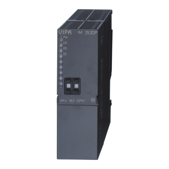
Manual VIPA System 300S Chapter 2 Hardware description Structure IM 353 353-1DP01 LED Status indicators IM 353DP Address selector The following components are beneath a flap DC 24V voltage supply RS485 interface VIPA 353-1DP01 DC24V PB DP PB DP Interfaces n. - Page 20 Chapter 2 Hardware description Manual VIPA System 300S Components LEDs The module carries a number of LEDs that are available for diagnostic purposes on the bus and for displaying the local status. The following table explains the different colors of the diagnostic LEDs.
- Page 21 Manual VIPA System 300S Chapter 2 Hardware description Power supply The PROFIBUS slave has an internal power supply. This power supply requires DC 24V. In addition to the electronics on the bus coupler, the supply voltage is also used to power any modules connected to the backplane bus.
-
Page 22: Technical Data
Chapter 2 Hardware description Manual VIPA System 300S Technical data Order no. 353-1DP01 Type IM 353DP SPEED-Bus Technical data power supply Power supply (rated value) DC 24 V Power supply (permitted range) DC 20.4...28.8 V Reverse polarity protection Current consumption (no-load operation) -
Page 23: Chapter 3 Deployment
Manual VIPA System 300S Chapter 3 Deployment Chapter 3 Deployment Overview This chapter describes the usage of the IM 353-1DP01 at the System 300. You may find here all information about project engineering, commissioning and diagnostic. Content Topic Page Chapter 3 Deployment .............. -
Page 24: Basics
Chapter 3 Deployment Manual VIPA System 300S Basics General PROFIBUS is an international standard applicable to an open fieldbus for building, manufacturing and process automation. PROFIBUS defines the technical and functional characteristics of a serial fieldbus system that can be used to create a low (sensor-/actuator level) or medium (process level) performance network of programmable logic controllers. - Page 25 Manual VIPA System 300S Chapter 3 Deployment Master and slaves PROFIBUS distinguishes between active stations (master) and passive stations (slave). Master devices Master devices control the data traffic at the bus. It is also possible to operate with multiple masters on a PROFIBUS. This is referred to as multi- master operation.
- Page 26 Chapter 3 Deployment Manual VIPA System 300S The bus transfer protocol provides two alternatives for the access to the Communication bus: Master with Master communication is also referred to as token-passing procedure. The master token-passing procedure guarantees the accessibility of the bus. The permission to access the bus is transferred between individual devices in the form of a "token".
- Page 27 Manual VIPA System 300S Chapter 3 Deployment DP-V0 provides the basic functionality of DP, including cycle data Function exchange as well as station diagnostic, module diagnostic and channel- cyclic data related diagnostic. communication Data is transferred cyclically between the DP master and the DP slave by (DP-V0) means of transmit and receive buffers.
- Page 28 Chapter 3 Deployment Manual VIPA System 300S Bus cycle ≤ ≤ ≤ ≤ To ensure that the data transfer is synchronized the bus cycle time should always be less than or equal to the DP cycle time. DP cycle The parameter min_slave_interval = 3ms is located in the GSD-file.
- Page 29 Manual VIPA System 300S Chapter 3 Deployment The key feature of version DP-V1 is the extended function for acyclic data Function communication. This forms the requirement for parameterization and Acyclic data calibration of the field devices over the bus during runtime and for the communication introduction of confirmed interrupt messages.
- Page 30 Chapter 3 Deployment Manual VIPA System 300S Addressing with When addressing data, PROFIBUS assumes that the physical structure of Slot and Index the slaves is modular or it can be structured internally in logical functional units, so-called modules. This model is also used in the basic DP functions...
- Page 31 Manual VIPA System 300S Chapter 3 Deployment Services For the deployment of the DP-V1 services you have to take care that your Acyclic data CPU supports DP-V1 communication. More detailed information about this communication is to be found in the description of your CPU. The following system function...
- Page 32 Chapter 3 Deployment Manual VIPA System 300S PROFIBUS employs screened twisted pair cable on the basis of the RS485 Data transfer interface. The data transfer rate of the system is limited to a max. of medium as 12MBaud. RS485 interface The RS485 interface uses differential voltages.
-
Page 33: Project Engineering
Manual VIPA System 300S Chapter 3 Deployment Project engineering General For project engineering a DP master engineering tool can be used like the Siemens SIMATIC manager. Here you assign the according PROFIBUS DP slave modules to the DP master. A direct assignment takes place via the PROFIBUS address that you set at the DP slave address selector. - Page 34 Chapter 3 Deployment Manual VIPA System 300S Note Please note to place the following modules during hardware configuration to the first three slots: Config for Slot1 Config for Slot2 Config for Slot3 These modules are automatically placed using the Siemens SIMATIC...
- Page 35 Manual VIPA System 300S Chapter 3 Deployment Parameter data At usage of the IM 353-1DP01 (DP-V1) you have the following parameter IM 353-1DP01 data: DP-V1 Byte Bit 7 ... Bit 0 Default Bit 2 ... 0: 0 (fix) Bit 3: 0 = WD-Timebase 10ms...
-
Page 36: Dp-V1 Services
Chapter 3 Deployment Manual VIPA System 300S DP-V1 Services Overview For the deployment of the DP-V1 services you have to take care that your CPU supports DP-V1 communication. More detailed information about this is to be found in the description of your CPU. The following system function... - Page 37 Manual VIPA System 300S Chapter 3 Deployment Device Via the index A4h, the module configuration of DP slave can be monitored. configuration The assignment identification to module type can be found at the following table: Module type Identification Input byte...
-
Page 38: Dp-V1 - I&M Data
Chapter 3 Deployment Manual VIPA System 300S DP-V1 - I&M data Overview Identification and maintenance data (I&M) are stored information in a module which support you at: • check of the system configuration • discover of hardware changes • remove errors in a system Identification data (I data) are information of the module e.g. - Page 39 Manual VIPA System 300S Chapter 3 Deployment ... continue I&M data Access Preset Explanation SOFTWARE_REVISION read (4byte) Firmware version Firmware version of the module. Vxyz An increase of the firmware version also increases the hardware revision REVISION_COUNTER read (2byte) 0000h...
-
Page 40: Profibus Installation Guidelines
Chapter 3 Deployment Manual VIPA System 300S PROFIBUS installation guidelines • A PROFIBUS DP network may only be built up in linear structure. PROFIBUS in general • PROFIBUS DP consists of minimum one segment with at least one master and one slave. - Page 41 Manual VIPA System 300S Chapter 3 Deployment Bus connection The following picture illustrates the terminating resistors of the respective start and end station. Master Slave Slave RxD/TxD-P(B) RxD/TxD-P(B) RxD/TxD-P(B) RxD/TxD-N(A) RxD/TxD-N(A) RxD/TxD-N(A) Schirm Schirm Schirm Note! The PROFIBUS line has to be terminated with its ripple resistor. Please make sure to terminate the last participants on the bus at both ends by activating the terminating resistor.
- Page 42 Chapter 3 Deployment Manual VIPA System 300S Note! To connect this EasyConn plug, please use the standard PROFIBUS cable type A (EN50170). Starting with release 5 you also can use highly flexible bus cable: Lapp Kabel order no.: 2170222, 2170822, 2170322.
-
Page 43: Commissioning
Manual VIPA System 300S Chapter 3 Deployment Commissioning • Assemble your PROFIBUS system. Overview • Configure your master system. • Adjust a valid address of the PROFIBUS. • Transfer the configuration into your master. • Connect the master and slave modules with the PROFIBUS. - Page 44 Chapter 3 Deployment Manual VIPA System 300S After power on, the DP slave executes a self test. It controls its internal Start-up functions and the communication via the backplane bus. After the error free behavior IM start-up, the bus coupler switches into the state "ready". In this state, the...
-
Page 45: Diagnostic Functions
Manual VIPA System 300S Chapter 3 Deployment Diagnostic functions Overview PROFIBUS DP provides an extensive set of diagnostic functions for quick error localization. Diagnostic messages are transferred via the bus and collected by the master. At the DP-V1 the device related diagnostic has been improved as further function and is subdivided into the categories interrupts and status messages. - Page 46 Chapter 3 Deployment Manual VIPA System 300S The diagnostic messages that are created by the PROFIBUS slave have, Structure of the depending on the parameterization, a length of 58Byte. 353-1DP01 diagnostic data As soon as the PROFIBUS slave sends a diagnostic to the master, the max.
- Page 47 Manual VIPA System 300S Chapter 3 Deployment Identifier-related Via the Identifier-related diagnostic you gain information at which plug-in diagnostic location (module) an error has occurred. More detailed information about the error is available via the Module state and the channel-related diagnostic.
- Page 48 Chapter 3 Deployment Manual VIPA System 300S Module status The module status gives you detailed information about the error that occurred at a module. The module status can be activated via the parameterization and has the following structure: Module status Byte Bit 7 ...
- Page 49 Manual VIPA System 300S Chapter 3 Deployment Channel-related With the channel-related diagnostic you gain detailed information about the Diagnostic channel error within a module. For the usage of the channel-related diagnostic you have to release the diagnostic interrupt for every module via the parameterization.
- Page 50 Chapter 3 Deployment Manual VIPA System 300S Interrupts The interrupt section of the slave diagnostic shows informations about interrupt type and cause. It consists of max. 20Byte. For every slave diagnostic max. 1 interrupt can be send. The interrupt section is always the last part of the diagnostic telegram if activated it in the parameterization.
- Page 51 Manual VIPA System 300S Chapter 3 Deployment Interrupt status at diagnostic interrupt Bytes x+4 to x+7 (corresponds CPU diagnostic record set 0) Byte Bit 7 ... Bit 0 Bit 0: Module malfunction, i.e. a problem has been detected Bit 1: Internal error in the module...
- Page 52 Chapter 3 Deployment Manual VIPA System 300S … continue Interrupt status at diagnostic interrupt Bytes x+8 to x+19 (corresponds to CPU diagnostic record set 1) Byte Bit 7 ... Bit 0 70h: Module with digital inputs 71h: Module with analog inputs...