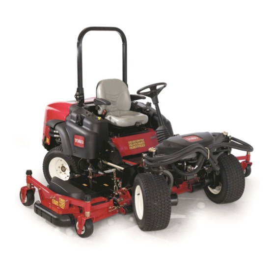
Toro Groundsmaster 360 Operator's Manual
4-wheel drive multi-purpose machine
Hide thumbs
Also See for Groundsmaster 360:
- Service manual (497 pages) ,
- Operator's manual (60 pages) ,
- Installation instructions manual (8 pages)

Related Manuals for Toro Groundsmaster 360


Summary of Contents for Toro Groundsmaster 360
- Page 1 Form No. 3428-990 Rev A Groundsmaster ® 360 4-Wheel Drive Multi-Purpose Machine Model No. 31200—Serial No. 403400001 and Up Model No. 31202—Serial No. 403400001 and Up *3428-990* A Register at www.Toro.com. Original Instructions (EN)
- Page 2 Whenever you need service, genuine Toro parts, or additional information, contact an Authorized Service The enclosed engine owner's manual is supplied Dealer or Toro Customer Service and have the model for information regarding the US Environmental and serial numbers of your product ready.
-
Page 3: Table Of Contents
Contents Servicing the Engine Oil........52 Servicing the Diesel-Oxidation Catalyst (DOC) and the Soot Filter ......53 Safety ............... 4 Fuel System Maintenance ........54 General Safety ........... 4 Servicing the Water Separator ......54 Safety and Instructional Decals ......4 Servicing the Engine Fuel Filter ...... -
Page 4: Safety
Safety • Keep your hands and feet away from rotating parts. Keep clear of the discharge opening. • Keep bystanders and children out of the operating This machine has been designed in accordance with area. Never allow children to operate the machine. ANSI B71.4-2017. - Page 5 decal106-9206 106-9206 1. Wheel torque specifications 2. Read the Operator's Manual. decal117-3233 decal117-3272 117-3233 117-3272 1. Read the Operator's Manual for information on fuses. 1. Warning—read the Operator's Manual; failure to use the rollover protection system (ROPS) can result in injury in the 2.
- Page 6 decalbatterysymbols Battery Symbols Some or all of these symbols are on your battery. 1. Explosion hazard 6. Keep bystanders away from the battery. 2. No fire, open flame, or 7. Wear eye protection; smoking explosive gases can cause blindness and other injuries.
- Page 7 decal125-4399 125-4399 1. Lower the deck 4. Slow 7. Engine—start 2. Raise the deck 5. Engine—shut off 8. 2-wheel steering 3. Fast 6. Engine—run 9. 4-wheel steering decal121-8378 121-8378 Model with Cab Only 1. Fan—off 5. External air 2. Fan—on full 6.
- Page 8 decal125-9248 125–9248 Model with Cab Only 1. Raise/Lower decks 5. Fast 2. Engine—stop 6. Slow 3. Engine—run 7. 2-wheel steering 4. Engine—start 8. 4–wheel steering decal130-0611 130-0611 Model with Cab Only 1. Warning—1) Remove the pin; 2) Raise the doors; 3) Exit the cab decal132-3600 132-3600...
- Page 9 decal132-6553 132-6553 Model with Cab Only 1. Height of cut decal130-0594 130-0594 Model with Cab Only decal133-8062 133-8062 1. Warning—read the Operator’s Manual; when sitting in the cab, always wear a seat belt; wear hearing protection. decal120-0250 decal132-6552 120-0250 132-6552 2-Wheel Drive with ROPS and 4-Wheel Drive with ROPS 1.
- Page 10 decal131-1946 131–1946 1. Engine oil 4. Diesel fuel 2. Hydraulic fluid 5. Parking brake 3. Engine coolant 6. Read the Operator’s Manual for more information on servicing the machine.
-
Page 11: Setup
Setup Loose Parts Use the chart below to verify that all parts have been shipped. Procedure Description Qty. PTO driveshaft Bolt (5/16 x 1-3/4 inches) Install the PTO driveshaft to a optional cutting unit or QAS. Locknut (5/16 inch) Roll pin (3/16 x 1-1/2 inches) Retainer pin Use the hardware to install the optional Grease fitting... -
Page 12: Using The Optional Cutting-Unit-Mounting Hardware
Torque the locknuts to 20 to 25 N∙m (175 to 225 in-lb). Lubricate the grease fittings on the PTO driveshaft. After you connect the other end of the driveshaft to the attachment gearbox shaft, connect the wire-harness connector to the PTO solenoid-valve-coil connector (Figure g018339... -
Page 13: Checking The Tire Pressure
Install the model year decal next to the serial number plate on the machine (Figure Note: For EN ISO 5395, complete the installation of the CE Kit. Contact your authorized Toro distributor for the correct CE Kit. Checking the Tire Pressure No Parts Required Procedure Check the tire pressure;... -
Page 14: Product Overview
Product Overview you, press the foot pedal and release it when the steering wheel reaches the desired operating position. Controls Key Switch Become familiar with all the controls before you start The key switch has 3 positions: O REHEAT the engine and operate the machine. and S (Figure TART... - Page 15 InfoCenter button is labeled with an icon displaying its current function. The InfoCenter LCD display shows the operating status, various diagnostics, and other information InfoCenter Icon Description about the machine (Figure SERVICE DUE Indicates when scheduled service Important: If the cutting unit shuts down and should be performed the InfoCenter temperature-warning icon is on, Engine rpm/status—indicates the...
- Page 16 CAN bus High exhaust temperature InfoCenter NOx control diagnosis malfunction; Bad or failed drive the machine back to the shop and contact your authorized Toro distributor (software version T and Bulb later). Output of TEC controller or control Using the Menus...
- Page 17 The factory default PIN code for you machine machine inputs such as is either 0000 or 1234. accessories and A/C clutch If you changed the PIN code and forgot the code, contact your authorized Toro distributor for assistance. Settings Menu Item Description From the M...
-
Page 18: Cab Controls
Cab Controls Model with Cab Only g198816 Figure 12 1. Fan control 4. Air-conditioning switch 2. Temperature control 5. Air-recirculation control 3. Windshield-wiper switch g028522 Figure 11 Air-Recirculation Control Sets the cab to either recirculate the air in the cabin or To enter the PIN code, press the center button to draw air into the cabin from outside (Figure... - Page 19 g196911 Figure 13 1. Windshield latch Rear Window Latch Lift up the latches to open the rear window. Press in on the latch to lock the window in position. Pull OPEN out and down on the latch to close and secure the window (Figure 13).
-
Page 20: Specifications
Specifications Note: Specifications and design are subject to change without notice. g198083 Figure 15 Description Figure 15 Dimension or Weight Reference Height with roll bar up 202 cm (80 inches) Height with roll bar down 140 cm (55 inches) Height with cab 225 cm (88-1/2 inches) Overall length 276 cm (108-1/2 inches) -
Page 21: Attachments/Accessories
Authorized Service Dealer or authorized Toro • Know how to stop the machine and shut off the distributor or go to www.Toro.com for a list of all engine quickly. approved attachments and accessories. •... -
Page 22: Adding Fuel
• Do not use fuel additives. • Contact your authorized Toro distributor if you wish for more information on biodiesel. Petroleum Diesel Cetane rating: 45 or higher Fuel Tank Capacity Sulfur content: Ultra-low sulfur (<15 ppm) 51 L (13.5 US gallons) -
Page 23: Checking The Engine-Oil Level
Test the safety interlock system before you use the System machine each time. If the safety system does not operate as described below, have an authorized Toro Before you start the engine and use the machine, distributor repair the safety system immediately. -
Page 24: Positioning The Standard Seat
Changing the Seat Suspension seat. On 2-wheel-drive machines, the engine should stop within 2 seconds. On 4-wheel-drive You can adjust the seat to provide a smooth and machines, the cutting unit shuts off and the comfortable ride. Position the seat where you are engine continues to run. -
Page 25: Adjusting The Height Of Cut
the pin, and rotate it down to lock it in place (Figure 21). Note: There are 4 rows of hole positions (Figure 21). The top row gives you the height of cut listed above the pin. The second row down gives you the height listed plus 6 mm (1/4 inch). -
Page 26: During Operation
• Use accessories, attachments, and replacement • Use your full attention while operating the parts approved by Toro only. machine. Do not engage in any activity that causes distractions; otherwise, injury or property damage may occur. Rollover Protection System •... - Page 27 Using the Rollover-Protection • A cab installed by Toro is a roll bar. System (ROPS) • Always wear your seat belt. WARNING Slope Safety A rollover accident can cause injury or death. • Slopes are a major factor related to loss of control and rollover accidents, which can result in severe •...
-
Page 28: Starting The Engine
g026090 Figure 23 1. InfoCenter 3. Engine-speed switch 4. Key switch 2. Power-takeoff (PTO) switch Turn the key clockwise to the R position. Note: The InfoCenter glow-plug icon turns on g014172 Figure 22 in 6 seconds. 1. Pin 3. Roll bar (raised position) After the InfoCenter glow-plug icon goes out, 2. -
Page 29: Driving The Machine
Switching from 4-Wheel Steering Remove the key to prevent the engine from accidentally starting and before you transport to 2-Wheel Steering or store the machine. Press the steering-selector switch (Figure 24) to the Note: Remove the key; otherwise, the fuel forward position. -
Page 30: Cutting Grass With The Machine
Disengaging the PTO To disengage, push the PTO switch to the position. Cutting Grass with the Machine Note: Cutting grass at a rate that loads the engine promotes DPF regeneration. g026088 Figure 25 Move the machine to the job site. 1. -
Page 31: Diesel Particulate Filter Regeneration
Diesel Particulate Filter Operate and maintain your machine with the function of the DPF in mind. Engine load at high idle (full Regeneration throttle) engine speed generally produces adequate exhaust temperature for DPF regeneration. The diesel particulate filter (DPF) is part of the exhaust Important: Minimize the amount of time that you system. - Page 32 DPF Ash Accumulation • When enough ash accumulates, the engine computer sends information to the InfoCenter • The lighter ash is discharged through the exhaust in the form of an engine fault to indicate the system; the heavier ash collects in the soot filter. accumulation of ash in the DPF.
- Page 33 Types of Diesel Particulate Filter Regeneration Types of diesel particulate filter regeneration that are performed while the machine is operating: Type of Regeneration Conditions that cause DPF regeneration DPF description of operation Passive Occurs during normal operation of the machine at •...
- Page 34 Types of diesel particulate filter regeneration that require you to park the machine: (cont'd.) Type of Regeneration Conditions that cause DPF regeneration DPF description of operation Recovery Occurs because the operator ignored requests for • When the reset-standby/parked or recovery a parked regeneration and continued operating the machine, adding more soot to the DPF regeneration icon...
- Page 35 press the right button to select the Technician entry DPF Operation Table (cont'd.) (Figure 34). State Description Reset Regen The engine computer is running a reset regeneration. The engine computer is requesting that Parked Stby you run a parked regeneration. Parked Regen You initiated a parked regeneration request and the engine computer is...
- Page 36 Assist DPF Regeneration • The icon displays in the InfoCenter while the reset regeneration is processing. • The engine computer adjusts engine settings to • Whenever possible, do not shut off the engine or raise the exhaust temperature. reduce engine speed while the reset regeneration •...
- Page 37 g227304 g224394 Figure 39 Figure 41 Press the right button to change the inhibit Note: If the engine exhaust temperature is too low, regeneration setting from On to Off (Figure the InfoCenter displays A #186 (Figure 42) to DVISORY or from Off to On (Figure 40).
- Page 38 Parked or Recovery Regeneration regeneration required—power takeoff disabled #189 (Figure 46). DVISORY • When the engine computer requests either a parked regeneration or a recovery regeneration, the regeneration request icon (Figure 43) displays in the InfoCenter. g224398 Figure 46 Important: Perform a parked regeneration to restore the PTO function;...
- Page 39 Important: Perform a recovery regeneration Move the machine outside to an area away from to restore the PTO function; refer to Preparing combustible materials. to Perform a Parked or Recovery Regeneration Park the machine on a level surface. (page 39) Performing a Parked or Recovery Regeneration (page 39).
- Page 40 At the DPF checklist screen, verify that the parking brake is engaged and that the engine speed is set to low idle (Figure 54). g224402 g224407 g224629 Figure 52 At the V screen, verify that you g227679 ERIFY FUEL LEVEL Figure 54 have 1/4 tank of fuel if you are performing the parked regeneration or 1/2 tank of fuel if you are...
- Page 41 The InfoCenter displays the I NITIATING Check Message and Corrective Action Table message (Figure 56). EGEN (cont'd.) g224411 Corrective Action: Start and run the engine. g227681 Figure 56 Corrective Action: Run the engine to warm the coolant The InfoCenter displays the time to complete temperature to 60°C (140°F).
- Page 42 Canceling a Parked or Recovery Regeneration displays A #183 (Figure 59). Press the DVISORY left button to exit to the home screen. Use the Parked Regen Cancel or Recovery Regen Cancel setting to cancel a running parked or recovery regeneration process. Access the DPF Regeneration menu (Figure 61).
-
Page 43: Operating Tips
• Alternating Mowing Direction If a blade is damaged or worn, replace it immediately with a genuine Toro replacement Alternate mowing direction to avoid making ruts in the blade. Refer to the cutting unit Operator’s Manual turf over time. This also helps the disperse clippings, for instructions to replace the blade. -
Page 44: Hauling The Machine
Pushing the Machine • Use full-width ramps for loading the machine into a trailer or a truck. Disengage the power takeoff (PTO), turn the key • Tie the machine down securely. to the O position, remove the key, and engage the parking brake. -
Page 45: Maintenance
Determine the left and right sides of the machine from the normal operating position. Download a free copy of the electrical or hydraulic schematic by visiting www.Toro.com and searching for your machine from the Manuals link on the home page. - Page 46 Maintenance Service Maintenance Procedure Interval • Change the engine oil and filter. Every 250 hours • Clean the cab air filters; replace them if they are torn or excessively dirty. • Service the air cleaner (earlier if the air cleaner indicator shows red, and more frequently in extremely dirty or dusty conditions).
-
Page 47: Daily Maintenance Checklist
Daily Maintenance Checklist Duplicate this page for routine use. For the week of: Maintenance Check Item Monday Tuesday Wednesday Thursday Friday Saturday Sunday Check the safety-interlock operation. Check the brake operation. Check the engine-oil level. Check the cooling-system-fluid level. Drain the water/fuel separator. -
Page 48: Pre-Maintenance Procedures
Notation for Areas of Concern Inspection performed by: Item Date Information Pre-Maintenance Procedures CAUTION If you leave the key in the key switch, someone could accidently start the engine and seriously injure you or other bystanders. Remove the key from the key switch before you do any maintenance. -
Page 49: Lubrication
Lubrication Greasing the Bearings and the grease fittings immediately after every washing, regardless of interval specified. Bushings Wipe the grease fittings clean so that foreign Service Interval: Every 50 hours Grease the bearing matter cannot be forced into the bearing or and bushing grease fittings more bushing (Figure... - Page 50 Note: To access the grease fittings for the migration through both the upper and lower king-pin rear-steering linkage, remove the storage bushings. You should see grease purging out of both compartment. the top and the bottom of the axle casting/bushing assembly areas of all 4 kingpin assemblies (Figure Note:...
-
Page 51: Engine Maintenance
Engine Maintenance Engine Safety • Shut off the engine and remove the key before checking the oil or adding oil to the crankcase. • Do not change the governor speed or overspeed the engine. Servicing the Air Cleaner Service Interval: Before each use or daily—Check the air-cleaner indicator. -
Page 52: Servicing The Engine Oil
Reset the indicator (Figure 68) if it shows red. Servicing the Engine Oil Oil Specification Use Toro Premium Engine Oil or another high-quality, low-ash engine oil that meets or exceeds the following specifications: • API service category CJ-4 or higher •... -
Page 53: Servicing The Diesel-Oxidation Catalyst (Doc) And The Soot Filter
Figure 72 the soot filter of the DPF. Refer to your authorized Toro distributor for diesel-oxidation catalyst and the soot filter Add oil to the crankcase; refer to Checking the replacement parts or service. -
Page 54: Fuel System Maintenance
Fuel System Maintenance Note: Refer to Fuel Specification (page 22) for the proper fuel recommendations. DANGER Under certain conditions, diesel fuel and fuel vapors are highly flammable and explosive. A fire or explosion from fuel can burn you and others and can cause property damage. •... -
Page 55: Servicing The Engine Fuel Filter
Servicing the Engine Fuel Cleaning the Fuel Pick-Up Filter Tube Screen Service Interval: Every 400 hours The fuel pick-up tube, located inside the fuel tank, is equipped with a screen to help prevent debris from Clean the area around the filter head (Figure 76). -
Page 56: Electrical System Maintenance
Electrical System WARNING Incorrect battery cable routing could damage Maintenance the machine and cables causing sparks. Sparks can cause the battery gasses to Important: Whenever working with the electrical explode, resulting in personal injury. system, always disconnect the battery cables, negative (-) cable first, to prevent possible wiring •... -
Page 57: Storing The Battery
Drive System Maintenance Checking the Tire Pressure Service Interval: Every 50 hours Maintain the air pressure in the front and rear tires. The correct air pressure is 172 kPa (25 psi) in the rear tires and 103 kPa (15 psi) in the front tires. If a cab is installed on the machine, the front and rear tires should be inflated to 172 kPa (25 psi). -
Page 58: Cooling System Maintenance
Cooling System synchronization of the wheel alignment should occur. Maintenance Important: Doing this procedure on turf can result in turf damage directly under each of the turning tires. Cooling System Safety • Swallowing engine coolant can cause poisoning; keep out of reach from children and pets. •... -
Page 59: Cleaning The Radiator
Cleaning the Radiator Brake Maintenance Service Interval: Before each use or daily Clean the radiator more frequently in extremely Adjusting the Brakes dusty and dirty conditions. Adjust the service brakes when there is more than 25 Keep the radiator clean to prevent the engine from mm (1 inch) of free travel of the brake pedal, or when overheating. -
Page 60: Adjusting The Parking Brake
Adjusting the Parking Belt Maintenance Brake Checking the Alternator If the parking brake fails to engage, adjust the brake pawl. Belt Loosen the 2 screws securing the parking-brake Service Interval: After the first 10 hours pawl to the frame (Figure 85). -
Page 61: Controls System Maintenance
Controls System Maintenance Adjusting the Traction Drive for Neutral Note: If the machine has recently had the hydraulic fluid changed or the traction motors or hoses replaced, work out any air trapped in the system prior to performing this procedure. To do this, operate the machine in forward and reverse for a few minutes and then replenish the oil as required. -
Page 62: Hydraulic System Maintenance
Toro Premium Transmission/Hydraulic Tractor and hold it there. Fluid (Available in 19 L (5 gallon) pails or 208 L (55 gallon) drums. See the Parts Catalog or your Toro Note: Maintain only light pressure on the pedal Distributor for part numbers). -
Page 63: Changing The Hydraulic Fluid And Filter
Important: Do not engage the PTO. Place a large pan under the hydraulic reservoir and transmission case and remove the plugs, Raise the deck to extend the lift cylinders, shut draining all of the hydraulic fluid (Figure 90). off the engine, and remove the key. Remove the hydraulic-filler cap (Figure 89) from... -
Page 64: Cab Maintenance
Cleaning the Cab Air Filters Cab Maintenance Service Interval: Every 250 hours Filling the Washer-Fluid Remove the screws and grates from both the in-cab and rear cab air filters (Figure 92 Bottle Figure 93). Perform the pre-maintenance procedure; refer Maintenance Safety (page 45). -
Page 65: Cleaning The Air-Conditioning Coil
Important: If either filter has a hole, tear, or Remove the 2 knobs that secure the fan-panel other damage, replace the filter. assembly and fans to the underside of the cab (Figure 95) and remove the assembly. Install the filters and the grate with the thumbscrews. -
Page 66: Cleaning
4. Do not pressure-wash under the rear overhang. a wire brush and baking-soda solution. Coat the cable terminals and battery posts with Grafo 112X skin-over grease (Toro Part No. 505-47) or petroleum jelly to prevent Waste Disposal corrosion. Engine oil, batteries, hydraulic fluid, and engine Slowly charge the battery for 24 hours every coolant are pollutants. - Page 67 Change the engine oil and filter; refer to Changing the Engine Oil and Filter (page 52). Fill the engine with the designated quantity of engine oil; refer to Checking the Engine-Oil Level (page 52). Start the engine and run it at idle speed for 2 minutes.
- Page 68 Notes:...
- Page 69 Notes:...
- Page 70 Notes:...
- Page 71 While the exposure from Toro products may be negligible or well within the “no significant risk” range, out of an abundance of caution, Toro has elected to provide the Prop 65 warnings. Moreover, if Toro does not provide these warnings, it could be sued by the State of California or by private parties seeking to enforce Prop 65 and subject to substantial penalties.
- Page 72 Countries Other than the United States or Canada Customers who have purchased Toro products exported from the United States or Canada should contact their Toro Distributor (Dealer) to obtain guarantee policies for your country, province, or state. If for any reason you are dissatisfied with your Distributor's service or have difficulty obtaining guarantee information, contact your Authorized Toro Service Center.