Makita PV7000C Technical Information
Disc sander
Hide thumbs
Also See for PV7000C:
- Instruction manual (56 pages) ,
- Instruction manual (45 pages) ,
- Instruction manual (12 pages)
Advertisement
Quick Links
T
ECHNICAL INFORMATION
Models No.
Description
C
ONCEPTION AND MAIN APPLICATIONS
PV7000C, PV7001C
These polishers have been developed for the most controlled operation in
various polishing works, featuring ;
Compact and light-weighted body
Electronic control for the least speed reduction
Variable speed change dial and speed selecting button (low/high) for a
wide range of polishing works
*Protection from electric shock
PV7000C : double insulation, PV7001C : by grounding
PV7001
The economy version of PV7001C ;
Features single speed without electronic control.
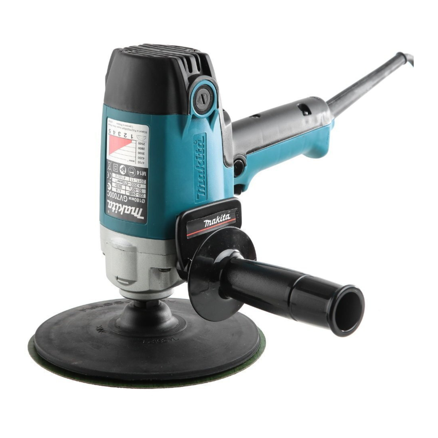
GV7000C
Easy-to-control Disc Sander has been developed on the same concepts as
the PV line-up.
Features variable speed from 2,500 to 4,700 rpm. (without speed selecting
button)
GV7000
The economy version of GV7000C ;
Features single speed without electronic control.
Specifications
Voltage
Model
(V)
100
110
PV7000C
120
PV7001C
220
GV7000C
230
240
Voltage
Model
(V)
100
110
PV7001
120
GV7000
220
230
240
No load speed : min
Polishing/sanding capacity : mm (")
Speed electing button for Low (single)
or High (variable)
Variable speed control dial
Electronic speed control
Electronic soft start
Protection from electric shock
Overall length : mm (")
Net weight : kg (lbs)
Cord length : m (ft)
PV7000C, PV7001C, PV7001
GV7000C, GV7000
PV7000C, PV7001C, PV7001 : Polisher 180mm
GV7000C, GV7000 : Disc Sander 180mm
Current
Cycle
(A)
(Hz)
9.5
50/60
8.6
50/60
7.9
50/60
4.3
50/60
4.1
50/60
50/60
3.9
Current
Cycle
(A)
(Hz)
5.8
50/60
5.3
50/60
4.8
50/60
2.6
50/60
2.5
50/60
50/60
2.4
PV7000C
=rpm
600 / 600 - 2,000 (Changeable)
-1
Double insulation
Continuous Rating (W)
Input
Output
900
400
900
400
400
900
400
900
900
400
900
400
Continuous Rating (W)
Input
Output
550
300
550
300
550
300
550
300
550
300
550
300
PV7001C
Wool bonnet 180 (7)
Yes
Yes
Yes
Yes
By grounding
210 (8-1/4)
2.0 (4.4)
2.5 (8.2)
W
H
Dimensions : mm ( " )
Length (L)
Height (H)
Width (W)
Max. Output
(W)
1,000
1,000
1,000
1,000
1,000
1,000
Max. Output
(W)
450
450
450
450
450
450
PV7001
GV7000C
1,700
2,500 - 4,700
Abrasive disc 180 (7)
No
No
Yes
No
Yes
No
Yes
Double insulation
210 (8-1/4)
4.0 (13.1) for Europe
PRODUCT
P 1 / 15
L
210 (8-1/4)
220 (8-5/8)
82 (3-1/4)
GV7000
4,700
No
No
No
No
2.0 (4.4)
Advertisement

Related Manuals for Makita PV7000C


Summary of Contents for Makita PV7000C
- Page 1 Length (L) 210 (8-1/4) *Protection from electric shock Height (H) 220 (8-5/8) PV7000C : double insulation, PV7001C : by grounding 82 (3-1/4) Width (W) PV7001 The economy version of PV7001C ; Features single speed without electronic control.
-
Page 2: Standard Equipment
P 2 / 15 Standard equipment PV7000C, PV7001C, PV7001 : Wrench 17, Side Grip, Pad 165 (Hook and Loop type) GV7000C, GV7000 : Wrench 17, Side Grip, Lock Nut Wrench 28, Sanding Lock Nut, Abrasive Disc 180 (#80), Rubber Pad 170 (Conventional type) Note : The standard equipment for the machine may differ from country to country. - Page 3 P 3 / 15 epair <1> Disassembling gear and ball bearing (1) Disassembling gear housing by unscrewing 4 pcs. of tapping screws 5x40. See Fig.1. Tapping screws 5x40 Gear housing Gear housing cover Motor housing Fig.1 (2) Unscrew bearing retainer clockwise with No.1R043 "wrench for bearing retainer". See Fig.2.
- Page 4 P 4 / 15 epair <2> Assembling gear and ball bearing (1) Assemble oil seal to bearing retainer. And then, assemble spindle to the bearing retainer as illustrated in Fig.4. (2) Assemble spindle to ball bearing 6201DDW by pressing it as illustrated in Fig.5. Press the spindle.
- Page 5 Fig.10 aution The caution is carved on the side grip for Model PV7000C as illustrated in Fig. 11. For efficiently prevention of static electricity accumulation, the above side grip is conductive in comparing with other side grips. Therefore, you would not be protected from electric shock, when you would hit the live wire with the other machine equipped with this side grip, for example, drill, hammer drill or angle grinder, etc.
-
Page 6: Wiring Diagram
P 6 / 15 ircuit diagram PV7001 (grounding type) equipped with 2 terminal switch, without controller Grounding (to be connected to gear housing) Color index of lead wires Black Green Field Switch Power supply cord Terminal block iring diagram Pass lead wires between pin and wall. - Page 7 P 7 / 15 ircuit diagram PV7001 (grounding type) equipped with 4 terminal switch, without controller Grounding (to be connected to gear housing) Color index of lead wires Black Green Field Switch Power supply cord iring diagram Terminal block Pass lead wires between pin and wall.
- Page 8 P 8 / 15 ircuit diagram PV7000C equipped with controller, 4 terminal switch, noise suppressor (for the market where the noise suppressor is required) Color index of lead wires Black Noise White Grounding suppressor (to be connected to field) Orange...
- Page 9 P 9 / 15 ircuit diagram PV7001C (grounding type) equipped with controller and 2 terminal switch (The noise suppressor is not used in some countries.) Color index of lead wires Black Grounding Noise suppressor White (to be connected to gear housing) Orange Green Controller...
- Page 10 P 10 / 15 ircuit diagram PV7001C (grounding type) equipped with controller and 4 terminal switch (for the market where the noise suppressor is not required) Color index of lead wires Grounding (to be connected to gear housing. This lead wire is not Black used in some countries.) White...
- Page 11 P 11 / 15 ircuit diagram GV7000 equipped with 2 terminal switch, without controller Color index of lead wires Black Switch Power supply cord iring diagram Pass lead wires between pin and wall. Pass lead wires so that they do not overlap each other, The space and press them into lead for controller...
- Page 12 ircuit diagram P 12 / 15 GV7000 equipped with 4 terminal switch and noise suppressor, without controller (The noise suppressor is not used in some countries.) Color index of lead wires Noise Black Grounding suppressor Transparent (to be connected to field) Field Switch Power supply...
- Page 13 P 13 / 15 ircuit diagram GV7000C equipped with controller and 2 terminal switch, (Noise suppressor is not used in some countries.) Color index of lead wires Noise Black suppressor White Orange Pick-up coil Controller Field Switch Power supply cord White or blue The other lead wires are a per the color index...
- Page 14 P 14 / 15 ircuit diagram GV7000C equipped with controller, 4 terminal switch (for the market where the noise suppressor is not required) Color index of lead wires Black White Orange Controller Field Switch Power supply cord Pick-up White or blue coil The other lead wires are a per the color index...
- Page 15 P 15 / 15 ircuit diagram GV7000C equipped with controller, 4 terminal switch, noise suppressor (for the market where the noise suppressor is required) Color index of lead wires Noise Black suppressor White Terminal for grounding to be connected to field. Orange Transparent Choke coil...