Table of Contents
Advertisement
Advertisement
Table of Contents

Related Manuals for Acer ICONIA TAB A510


Summary of Contents for Acer ICONIA TAB A510
- Page 1 ICONIA TAB A510 S E R V I C E G U I D E G U I D E...
-
Page 2: Table Of Contents
Table of Contents Chapter 1. Hardware Specifications and Configurations Features ............1-2 Tablet tour. - Page 3 ICONIA TAB A510 ........
- Page 4 Updates Copyright Copyright © 2012 by Acer Incorporated. All rights reserved. No part of this publication may be reproduced, transmitted, transcribed, stored in a retrieval system, or translated into any language or computer language, in any form or by any means, electronic, mechanical, magnetic, optical, chemical, manual or otherwise, without the prior written permission of Acer Incorporated.
- Page 5 Conventions The following conventions are used in this manual: WARNING: Indicates a potential for personal injury. CAUTION: Indicates a potential loss of data or damage to equipment. IMPORTANT: Indicates information that is important to know for the proper completion of a procedure, choice of an option, or completing a task.
- Page 6 For Acer-authorized service providers: Your Acer office may have a different part number code than those given in the FRU list of this printed service guide. The list provided by your regional Acer office must be used to order FRU...
- Page 7 CHAPTER Hardware Specifications and Configurations Hardware Specifications and Configurations ....1-2 Features ............1-2 Tablet tour .
-
Page 8: Chapter 1. Hardware Specifications And Configurations
Hardware Specifications and Configurations Features The following is a summary of the computer’s many features: Form Factor • 10.1” Tablet Operating System • Android Ice Cream Sandwich 4.0 Platform • T30s Cortex A9 Stepping A3, 1.3GHz ® • Ultra Low Power NVidia GeForce GPU with OpenGL ES 2.0 System Memory •... - Page 9 Connectivity Wi-Fi • IEEE 802.11 b/g/n Bluetooth ® • Bluetooth 2.1+EDR • Micro-B Hyper USB Client GPS/A-GPS • Wi-Fi SKU: Broadcom - stand alone, A-GPS not supported Expansion Slot • MicroSD memory card up to 32G (SDHC 2.0 compatible) Special Keys and Controls •...
- Page 10 Power Adapter and Battery Battery • Rechargeable Lithium-Ion polymer battery • Capacity 36W (9800mAh, 1S2P) Power Adapter • Voltage range/frequency: 100 ~ 240V AC, 50/60 Hz • DC output: 12V and 1.5 A, 18W Others • Reset hole Green Requirement •...
-
Page 11: Tablet Tour
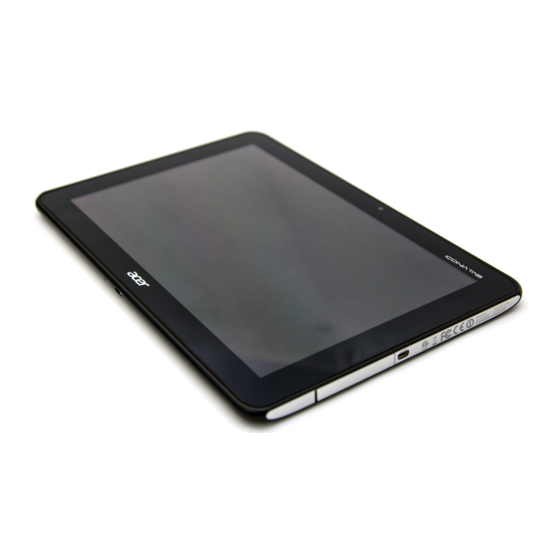
Tablet tour Front View Figure 1:1. Front View Item Description Detects ambient light and automatically adjusts the screen Light Sensor brightness. Camera A 1-megapixel camera for video chatting and self-portrait images. Touch Screen 10.1-inch, 1280 x 800 capacitive touch screen. Hardware Specifications and Configurations... -
Page 12: Rear View
Rear View Figure 1:2. Rear View Item Description Camera A 5-megapixel camera for taking high resolution images. Speakers Emits stereo audio. Microphone Receives audio input. Hardware Specifications and Configurations... -
Page 13: Top View
Top View Figure 1:3. Top View Icon Item Description Screen Rotation Use this switch to lock the screen rotation or allow the Lock Switch screen to match the orientation of the tablet. Volume Control Increases or decreases the tablet volume. Hardware Specifications and Configurations... -
Page 14: Bottom View
Bottom View Figure 1:4. Bottom View Icon Item Description Insert a pointed object, such as a paper clip, into the Reset Hole reset hole to reset the tablet to its factory defaults. Micro-B USB Port Connects to a computer with a USB cable. (slave) Hardware Specifications and Configurations... -
Page 15: Left View
Left View Figure 1:5. Left View Icon Item Description • Press and hold to turn the tablet on or off. Power Button • Press briefly to turn the screen on/off or enter sleep mode. Headset Jack Connects to stereo headphones. Hardware Specifications and Configurations... -
Page 16: Right View
Right View Figure 1:6. Right View Item Description Card Slot Cover Insert a microSD card into the slot under this cover. HDMI Micro (Type D) Connects to an HDMI cable with a Type D connector. Port 1-10 Hardware Specifications and Configurations... -
Page 17: System Block Diagram
System Block Diagram Figure 1:7. System Block Diagram Hardware Specifications and Configurations 1-11... -
Page 18: Specifications Table
Specifications Table Computer specifications Item Metric Imperial Dimensions Length 260 mm 10.23 in Width 175 mm 6.89 in Height (front to rear) 10.95 mm 0.431 in Weight (equipped with optical Under 680g for Wi-Fi SKU Under 1.45 lbs drive, flash drive, and battery) Weight (equipped with optical drive, flash drive, and without battery) - Page 19 ® Graphics Processor Ultra Low Power GeForce GPU supporting OpenGL ES 2.0 LVDS transmitter 1RLP105ANQG8_QFN148_11X11 TI PTPS6591102AA2ZRCR LDDR2 1G (Base on Acer’s AVL) ULPI Phy for USB Bluetooth Azurewave AW-NH660 Wireless Azurewave AW-NH660 BCM47511IFBG_FBGA100 GPS Low-Noise Amplifier APL5603-28BI-TRG_SOT23-5 TOUCH controller...
- Page 20 Processor Item Specification ® Cortex-A9 MPCore™ (Quad-Core) Processor with NEON technology CPU package 681 Ball 14*14mm IHS-FCCSP NOTE: No CPU Fan in this product. Processor Specifications Bus Speed Cach Core Item Cores Mfg Tech Package Speed (FSB/DMI/QBI) e Size Voltage 14 x 14 Quad 40nm...
- Page 21 Hard Disk Drive Interface Item Specification Sandisk Kingston Samsung SanDisk Vendor & S IC FL 16G S IC FL 16G S IC FL 32G S IC FL 32G Model Name SDIN5C1-16G KE4BT4B6A KLMBG8FEJA- SDIN4E2-32G TFBGA 169P FBGA169 A001 FW PA33 TFBGA 169P Capacity (GB)
- Page 22 Audio Amplifier IC Item Specification Amplifier IC APA2010HAI-TRG • Differential & Single-Ended input mode • Output Power at 1%THD+N • 2.4W, at VDD=5V, RL=4 ohm (WLCSP-9) • Output Power at 10%THD+N • 3.1W, at VDD=5V, RL=4 ohm (WLCSP-9) • No external output L-C filter required •...
- Page 23 Item Specification Physical Size (mm) 229.46 mm x 149.2 mm x 4.4 max (without touch) Electrical Interface 1 channel LVDS Viewing Angle (degree) Horizontal (Right) CR = 10 Min : 80 (Right) / 80 (Left) / 80 (Upper) / 80 (Lower) (Left) Typ : 85 (Right) / 85 (Left) / 85 (Upper) / 85 (Lower) Vertical (Upper) CR = 10...
- Page 24 3G Card Item Specification Features Not supported Wireless Module 802.11b/g/n Item Specification Chipset AW-NH660 SIP (include Broadcom BCM4330) 802.11b: 1, 2, 5.5, 11Mbps Data throughput 802.11g: 6, 9, 12, 18, 24, 36, 48, 54Mbps 802.11n:MCS 0~7 Protocol IEEE 802.11b/g/n, Wi-Fi compliant Interface SDIO/SPI Connector type...
- Page 25 Video Interface Item Specification Chipset N/A (Graphic function is embedded in CPU) Package Interface Compatibility Sampling rate VRAM Item Specification Chipset Memory size Interface USB Port Item Specification USB compliance level USB2.0 Modes Client / Device Speed High Number of USB port(s) 1 port for Device, Micro-B Hyper USB (5 + 12 pin) Location Bottom side...
- Page 26 AC Adapter Item Specification Total output power 0.5A(RMS)Max. @120Vac Maximum input AC current 0.25A(RMS)Max. @240Vac 40A Max. for 120VAC at Max load Inrush current 60A Max. for 240VAC at Max load (At cold start) Efficiency Meet EPA 2.0 System Power Management Item Specification Mech.
- Page 27 MicroSD Card Reader Item Specification Chipset SD function is supported by CPU. Package Interface SDIO Maximum supported size Follow up SD card spec Features Storage cards with adapter microSD™ System LED Indicator Item Specification • White color solid on: System on System state •...
- Page 28 Hardware IRQ System Function IRQ5* IRQ6 IRQ7* IRQ8 IRQ9* IRQ10* IRQ11 IRQ12 IRQ13 IRQ14 IRQ15 NOTE: Default configuration; audio possible configurations are IRQ5, IRQ7, IRQ9, IRQ10, or none. NOTE: ExpressCards may assert IRQ3, IRQ4, IRQ5, IRQ7, IRQ9, IRQ10, IRQ11, or IRQ15. Either the infrared or the serial port may assert IRQ3 or IRQ4.
- Page 29 I/O Address (hex) System Function (Shipping Configuration) 065 - 06F 070 - 071 072 - 07F 080 - 08F 090 - 091 093 - 09F 0A0 - 0A1 I/O Address (hex) 0A2 - 0BF 0C0 - 0DF 0E0 - 0EF 0F0 - 0F1 0F2 - 0FF 100 - 16F...
- Page 30 I/O Address (hex) System Function (Shipping Configuration) 2A0 - 2A7 2A8 - 2E7 2E8 - 2EF 2F0 - 2F7 2F8 - 2FF 300 - 31F 320 - 36F 370 - 377 378 - 37F 380 - 387 388 - 38B 38C - 3AF 3B0 - 3BB 3BC - 3BF...
- Page 31 CHAPTER Diagnostic Utilities Diagnostic Utilities ........2-2 Introduction .
-
Page 32: Chapter 2. Diagnostic Utilities
Diagnostic Utilities Introduction The ICONIA TAB A510 has a software tool designed to diagnose problems with its hardware components. Diagnostic Tool SOP Preparation • Diagnostic Tool • USB Driver of A510 for PC • USB cable • MicroSD card Tool Installation Install the USB driver in a PC/NB. - Page 33 Run Install QAJA0.bat. Figure 2:2. ACTP Folder Directory On the device, go to the applications screen and look for the diagnostic tool named ACTP. Figure 2:3. Device Applications Screen Tap the ACTP icon to start the testing process. (Figure 2:3) Diagnostic Utilities...
-
Page 34: Main Menu
Main Menu The diagnostic tool tests the Touch Panel, Display, Buttons, Speaker, Microphone, Camera, SD card and Vibrator functionality. Select the function(s) you want to test, and then tap OK to start. Step 1 – Select item(s) Step 2 – Click “OK”... - Page 35 2. Touch Linearity Test (Touch Panel) Draw your finger along the yellow squares. The result is Pass if you fill all the yellow squares and Fail if you do not. The program returns to the main menu after the test is finished. Figure 2:6.
- Page 36 4. Hardware Keys Test (Keys) Press the volume up, volume down and lock keys to verify if all keys work. A color change to green means key function works. Figure 2:8. Hardware Keys Test 5. Front Camera Aim the front side of the device at an object. Tap capture to test the picture taking functionality. Figure 2:9.
- Page 37 6. Speakers Loud tone sounds in the left speaker and then switches to the right speaker. Figure 2:10. Speakers Test 7. Microphone Tap the screen to start the test. When recording appears, speak into the top side of the device. Check the recorded sound quality when the screen shows replaying.
- Page 38 8. SD Card (SD Read/Write Test) Insert a microSD card into the device. Tap the screen to start the SD read and write test. The screen shows a success message if the test is successful. Figure 2:12. SD Card Test 9.
- Page 39 10. Rear Camera Aim the rear side of the device at an object. Tap the capture button to test the picture taking functionality of the rear camera. Figure 2:14. Rear Camera Test Diagnostic Utilities...
-
Page 40: Uninstallation Procedures
Uninstallation Procedures The diagnostic tool MUST be uninstalled once testing is done. IMPORTANT: DO NOT distribute this tool outside of the service center. On the device, go to Settings → Apps. Tap the QAJA0ACTP icon. Figure 2:15. Applications Menu Screen Tap Uninstall, and then tap OK to confirm. - Page 41 The Uninstall finished message appears, tap OK to complete the process. Figure 2:17. Uninstall Finished Diagnostic Utilities 2-11...
- Page 42 CHAPTER Service and Maintenance Service and Maintenance ........3-3 Introduction .
- Page 43 CHAPTER Service and Maintenance (cont.) WLAN Antenna Installation ........3-63 GPS Antenna Removal .
-
Page 44: Chapter 3. Service And Maintenance
Service and Maintenance Introduction This chapter contains general information about the tablet, a list of tools needed to perform the required maintenance and step by step procedures on how to remove and install components from the tablet computer. Recommended Equipment The following tools are required to perform maintenance on the tablet: •... -
Page 45: Maintenance Flowchart
Maintenance Flowchart The flowchart in Figure3-1 provides a graphic representation of the module removal and installation sequences. It provides information on what components need to be removed and installed during servicing Lower Case Microphone Function Microphone Speaker Camera (Front) Board (Rear) (Left) Docking... -
Page 46: Getting Started
Getting Started The flowchart (Figure 3:1, page 3-4) identifies sections illustrating the entire removal and installation sequence. Observe the order of the sequence to avoid damage to any of the hardware components. Perform the following prior to performing any maintenance procedures: Place the system on a flat work surface. -
Page 47: Sd Card Removal
SD Card Removal Open the SD card cover. Figure 3:3. Opening the SD Card Cover Push the SD card to eject it from the slot, and then remove the card. Figure 3:4. Removing the SD Card Service and Maintenance... - Page 48 Secure the SD card cover. Figure 3:5. Securing the SD Card Cover Service and Maintenance...
-
Page 49: Sd Card Installation
SD Card Installation Open the SD card cover. (Figure 3:3, page 3-6) Push the SD card into the slot until it clicks into place. Figure 3:6. Installing the SD Card Close the SD card cover. (Figure 3:5, page 3-7) Service and Maintenance... -
Page 50: Lower Case Removal
Lower Case Removal Prerequisite: SD Card Removal on page Open the SD card cover. Figure 3:7. Opening the SD Card Cover Insert the pointed plastic pry into the slot next to the SD card cover to unlock the latch. Figure 3:8. Unlocking the Right IO Cover Latches (1 of 4) Service and Maintenance... - Page 51 Starting from the edge shown in Figure 3-8, release the latches from the bezel with your hands. Figure 3:9. Unlocking the Right IO Cover Latches (2 of 4) Insert the plastic pry into the slot to unlock the lower latch. Figure 3:10.
- Page 52 Release the latches from the bezel with your hands. Figure 3:11. Unlocking the Right IO Cover Latches (4 of 4) Insert the plastic pry into the gap between the headset jack and the left IO cover, and then pry to unlock the left IO cover latch. Figure 3:12.
- Page 53 Release the latches from the bezel with your hands. Figure 3:13. Unlocking the Left IO Cover Latches (2 of 2) Remove the screws. Figure 3:14. Removing the Screws Service and Maintenance 3-12...
- Page 54 Release the left side of the lower case from the latches of the bezel. TIP: Place your wrist on the lower case and apply pressure while pulling the lower case from the bezel with your fingers. Figure 3:15. Releasing the Side Latches (1 of 3) Pry with both hands to release the side latches from the bezel.
- Page 55 Pull the bezel to release the right side of the lower case. Figure 3:17. Releasing the Side Latches (3 of 3) CAUTION: Do not abruptly pull the lower case from the bezel, connectors underneath must be disconnected first. Hold up the lower case and disconnect the battery cable from the mainboard connector. Figure 3:18.
- Page 56 Remove the protective tape covering the docking cable. Figure 3:19. Removing the Protective Tape Disconnect the docking cable from the mainboard connector. Figure 3:20. Disconnecting the Docking Cable Remove the lower case from the bezel. 3-15 Service and Maintenance...
-
Page 57: Lower Case Installation
Lower Case Installation Before installing the lower case, make sure the following are installed: • Rear microphone (if not, perform Microphone (Rear) Installation on page 3-67). • Docking board (if not, perform Docking Board Installation on page 3-70). Align the bottom side of the lower case to the bezel and connect the docking board cable connector to the mainboard connector. - Page 58 Connect the battery cable connector to the mainboard connector. Figure 3:23. Connecting the Battery Cable Align the right edge of the lower case with the connectors slot on the bezel. Figure 3:24. Installing the Lower Case (1 of 5) 3-17 Service and Maintenance...
- Page 59 Make sure the Lock key on the lower case (A) and the Lock key on the bezel (B) are on the unlock position. Figure 3:25. Installing the Lower Case (2 of 5) Using the plastic pry, slightly push the left side of the lower case to secure the left side of the bezel.
- Page 60 Install and secure the lower case to the bezel latches. Figure 3:27. Installing the Lower Case (4 of 5) Secure the screws to the bezel. Figure 3:28. Installing the Lower Case (5 of 5) 3-19 Service and Maintenance...
- Page 61 Install and secure the left IO cover to the bezel latches. Figure 3:29. Installing the Left IO Cover Install and secure the lower right IO cover to the bezel latches. Figure 3:30. Installing the Right IO Cover (1 of 2) Service and Maintenance 3-20...
- Page 62 Install and secure the upper right IO cover to the bezel latches. Figure 3:31. Installing the Right IO Cover (2 of 2) Close the SD card cover. Figure 3:32. Closing the SD Card Cover Table 3:2. Lower Case Screws Screw Name Screw Type Quantity M 2.0 x 4.0 Ni...
-
Page 63: Microphone (Front) Removal
Microphone (Front) Removal Prerequisite Lower Case Removal on page Remove the microphone cable connector from the mainboard connector. Figure 3:33. Removing the Front Microphone (1 of 2) Using the plastic pry, push up to remove the microphone from the slot. Figure 3:34. -
Page 64: Microphone (Front) Installation
Microphone (Front) Installation Install the microphone to the microphone slot of the bezel. Figure 3:35. Installing the Front Microphone (1 of 2) Route the microphone cable to pass underneath the battery cable (A) and the mainboard tab (B). Then, connect the microphone cable connector to the mainboard connector. Figure 3:36. -
Page 65: Camera Module Removal
Camera Module Removal Prerequisite: Lower Case Removal on page Disconnect the camera cable from the mainboard connector. Figure 3:37. Disconnecting the Camera Cable Using the plastic pry, remove the rear camera from the slot. Figure 3:38. Removing the Camera (1 of 3) Service and Maintenance 3-24... - Page 66 Using the plastic pry, push one side of the front camera to remove the camera out from the slot. Figure 3:39. Removing the Camera (2 of 3) Remove the camera module from the bezel. Figure 3:40. Removing the Camera (3 of 3) 3-25 Service and Maintenance...
-
Page 67: Camera Module Installation
Camera Module Installation Align the camera module to the camera slots and the connector on the mainboard. Figure 3:41. Aligning the Camera Module Push the front camera down to the slot until it locks into place. Figure 3:42. Installing the Camera (1 of 3) Service and Maintenance 3-26... - Page 68 Install the rear camera to the camera slot on the bezel. Figure 3:43. Installing the Camera (2 of 3) Connect the camera cable to the connector on the mainboard. Make sure the connectors click into place. Figure 3:44. Installing the Camera (3 of 3) Install the lower case (see Lower Case Installation on page 3-16).
-
Page 69: Function Board Removal
Function Board Removal Prerequisite: Lower Case Removal on page Remove the screws securing the function board to the bezel. Figure 3:45. Removing the Function Board Screws Insert the plastic pry into the headset jack and then lift to remove the function board from the latches on the bezel. - Page 70 Slightly pull the function board to remove the board from the bezel. Figure 3:47. Removing the Function Board (2 of 2) Turn the function board over and remove the protective tape covering the function board cable. Figure 3:48. Removing the Protective Tape 3-29 Service and Maintenance...
- Page 71 Disconnect the function board cable from the function board connector. Figure 3:49. Disconnecting the Function Board Cable Service and Maintenance 3-30...
-
Page 72: Function Board Installation
Function Board Installation Prerequisite: Battery Removal on page 3-37 Connect the function board cable connector (colored side up) to the function board connector. Figure 3:50. Connecting the Function Board Cable Secure the protective tape covering the function board connector. Figure 3:51. Securing the Protective Tape Install the battery (see Battery Installation on page 3-39). - Page 73 Align and push the function board to lock on the latches on the bezel. Figure 3:52. Securing the Function Board Secure the screws to the function board and the bezel. Figure 3:53. Installing the Camera (3 of 3) Install the lower case (see Lower Case Installation on page 3-16).
-
Page 74: Speaker (Left) Removal
Speaker (Left) Removal Prerequisite Lower Case Removal on page Remove the screws securing the speaker to the bezel. Figure 3:54. Removing the Speaker Screws Remove the protective tape covering the speaker cable. Figure 3:55. Removing the Protective Tape 3-33 Service and Maintenance... - Page 75 Partially lift the foam strip to release the speaker cable. Figure 3:56. Lifting the Foam Strip Remove the left speaker. Note that the speaker cable is routed through the guides around the battery. Figure 3:57. Removing the Left Speaker Table 3:3. Function Board Screws Screw Name Screw Type Quantity...
-
Page 76: Speaker (Left) Installation
Speaker (Left) Installation Install the left speaker. Be sure to route the speaker cable under the foam strip and through the guides around the battery. Figure 3:58. Installing the Speaker Secure the foam strip over the speaker cable to hold the cable in place. Figure 3:59. - Page 77 Secure the protective tape to hold the speaker cable in place. Figure 3:60. Securing the Protective Tape Install the lower case. (see Lower Case Installation on page 3-16). Table 3:4. Docking Board Screws Screw Name Screw Type Quantity M 1.6 x 3.0 Ni Service and Maintenance 3-36...
-
Page 78: Battery Removal
Battery Removal Prerequisite: Speaker (Left) Removal on page 3-33 Function Board Removal on page 3-28 Camera Module Removal on page 3-24 Figure 3:61. Modules to Remove Before Battery Removal Disconnect the GPS cable connector from the mainboard and set the cable aside. Note that the GPS cable is routed through the guides around the battery. - Page 79 Remove the screws securing the battery to the bezel. Figure 3:63. Removing the Battery Screws Remove the battery. Figure 3:64. Removing the Battery Service and Maintenance 3-38...
-
Page 80: Battery Installation
Battery Installation Before installing the battery, make sure the following are installed: • Touch Control Board (if not, perform Touch Control Board Installation on page 3-45). • Mainboard (if not, perform Mainboard Installation on page 3-59). Perform steps 1 and 2 of the Function Board Installation on page 3-31. - Page 81 Perform steps 4 and 5 of the Function Board Installation on page 3-31. Figure 3:67. Installing the Function Board Connect the GPS antenna connector to the mainboard connector. Then, route the GPS antenna cable to pass underneath the battery cable and through the guides around the battery. Figure 3:68.
- Page 82 Table 3:5. Battery Screws Screw Name Screw Type Quantity M 2.0 x 4.0 Ni 3-41 Service and Maintenance...
-
Page 83: Touch Control Board Removal
Touch Control Board Removal Prerequisite: Battery Removal on page 3-37 Remove the protective tape covering the touch control board. Figure 3:69. Removing the Protective Tape Disconnect touch control board cable from the touch control board. Figure 3:70. Disconnecting the Touch Control Board Cable Service and Maintenance 3-42... - Page 84 Remove the adhesive strip from the bezel. Figure 3:71. Removing the Adhesive Tape Disconnect the mylar touch control cable connectors. Figure 3:72. Disconnecting the Mylar Touch Control Cables 3-43 Service and Maintenance...
- Page 85 Pull up to remove the touch control board from the bezel. Figure 3:73. Removing the Touch Control Board Service and Maintenance 3-44...
-
Page 86: Touch Control Board Installation
Touch Control Board Installation Align and place the touch control board to its slot. Push slightly to secure the adhesives on the touch control board to the bezel. Figure 3:74. Installing the Touch Control Board Connect the mylar touch control cable connectors to the connectors on the touch control board. Figure 3:75. - Page 87 Secure the adhesive tape to hold the mylar touch control cables. Figure 3:76. Attaching the Adhesive Tape Connect the touch control board cable connector (colored side up) to the touch control board. Figure 3:77. Connecting the Touch Control Board Cable Service and Maintenance 3-46...
- Page 88 Attach the protective tape covering the touch control board. Figure 3:78. Attaching the Protective Tape Install the battery (see Battery Installation on page 3-39). 3-47 Service and Maintenance...
-
Page 89: Lvds Cable Removal
LVDS Cable Removal Prerequisite: Touch Control Board Removal on page 3-42 Remove the protective tape attached to the LVDS cable from the mainboard. Figure 3:79. Removing the LVDS Cable (1 of 4) Disconnect the LVDS cable connector from the mainboard connector. Figure 3:80. - Page 90 Remove the protective tape attached to the LVDS cable from the bezel. Figure 3:81. Removing the LVDS Cable (3 of 4) Disconnect the LVDS cable from the LCD panel connector. Figure 3:82. Removing the LVDS Cable (4 of 4) 3-49 Service and Maintenance...
-
Page 91: Lvds Cable Installation
LVDS Cable Installation Connect the LVDS cable connector to the LCD panel connector. Figure 3:83. Installing the LVDS Cable (1 of 4) Secure the protective tape to the bezel. Figure 3:84. Installing the LVDS Cable (2 of 4) Service and Maintenance 3-50... - Page 92 Connect the LVDS cable connector to the mainboard connector. Figure 3:85. Installing the LVDS Cable (3 of 4) Secure the protective tape to the mainboard. Figure 3:86. Installing the LVDS Cable (4 of 4) Install the touch control board (see Touch Control Board Installation on page 3-45).
-
Page 93: Speaker (Right) Removal
Speaker (Right) Removal Prerequisite: Touch Control Board Removal on page 3-42 Disconnect the speaker cable connector from the mainboard connector. Figure 3:87. Disconnecting the Speaker Cable Remove the screws securing the right speaker to the bezel. Figure 3:88. Removing the Right Speaker Screws Service and Maintenance 3-52... - Page 94 Remove the right speaker from the bezel. Figure 3:89. Remove the Right Speaker 3-53 Service and Maintenance...
-
Page 95: Speaker (Right) Installation
Speaker (Right) Installation Install the right speaker to the bezel. Figure 3:90. Installing the Right Speaker Secure the screws to the right speaker and the bezel. Figure 3:91. Securing the Right Speaker Screws Service and Maintenance 3-54... - Page 96 Connect the speaker cable connector to the mainboard connector. Figure 3:92. Connecting the Speaker Cable Connector Install the touch control board (see Touch Control Board Installation on page 3-45). Table 3:6. Left Speaker Screws Screw Name Screw Type Quantity M 1.6 x 3.0 Ni 3-55 Service and Maintenance...
-
Page 97: Mainboard Removal
Mainboard Removal Prerequisite: Battery Removal on page 3-37 Disconnect the following connectors from the mainboard connectors: • Speaker cable connector (A) • LVDS cable connector (B) • WLAN antenna connector (C) • Front microphone connector (D) Figure 3:93. Disconnecting the Cables from the Mainboard Service and Maintenance 3-56... - Page 98 Remove the screws securing the mainboard to the bezel. Figure 3:94. Removing the Mainboard Screws On the bottom side of the mainboard, disconnect the touch control cable connector. Figure 3:95. Disconnecting the Touch Control Cable 3-57 Service and Maintenance...
- Page 99 Remove the protective tape covering the function board connector. Figure 3:96. Removing the Protective Tape Disconnect the function board cable connector from the mainboard connector. Figure 3:97. Removing the Protective Tape Service and Maintenance 3-58...
-
Page 100: Mainboard Installation
Mainboard Installation Connect the function board cable connector (with MB label side up) to the mainboard connector. Figure 3:98. Connecting the Function Board Cable Secure the protective tape covering the function board connector. Figure 3:99. Attaching the Protective Tape 3-59 Service and Maintenance... - Page 101 Connect the touch control board cable connector (with MB label side up) to the mainboard connector. Figure 3:100. Connecting the Touch Control Board Cable Secure the mainboard screws. Figure 3:101. Securing the Mainboard Screws Service and Maintenance 3-60...
- Page 102 Connect the following cable connectors: • Speaker cable connector (A) • LVDS cable connector (B) • WLAN antenna connector (C) • Front microphone connector (D) Figure 3:102. Connecting the Cables to the Mainboard Install the battery (see Battery Installation on page 3-39). Table 3:7.
-
Page 103: Wlan Antenna Removal
WLAN Antenna Removal Prerequisite: Mainboard Removal on page 3-56 Peel off the WLAN antenna metallic tape from the bezel. Figure 3:103. Removing the WLAN Antenna (1 of 2) Using the plastic pry, remove the WLAN antenna from the bezel. Figure 3:104. Removing the WLAN Antenna Service and Maintenance 3-62... -
Page 104: Wlan Antenna Installation
WLAN Antenna Installation Using the tweezers, align and install the WLAN antenna to the antenna slot on the bezel. Figure 3:105. Installing the WLAN Antenna (1 of 2) Attach the metallic tape to secure the WLAN antenna to the bezel. Figure 3:106. -
Page 105: Gps Antenna Removal
GPS Antenna Removal Prerequisite: Mainboard Removal on page 3-56 Peel off the GPS antenna metallic tape from the bezel. Figure 3:107. Removing the GPS Antenna (1 of 2) Using the plastic pry, remove the GPS antenna from the bezel. Figure 3:108. Removing the GPS Antenna (2 of 2) Service and Maintenance 3-64... -
Page 106: Gps Antenna Installation
GPS Antenna Installation Using the tweezers, align and install the GPS antenna to the antenna slot on the bezel. Figure 3:109. Installing the GPS Antenna (1 of 2) Attach the metallic tape to secure the GPS antenna to the bezel. Figure 3:110. -
Page 107: Microphone (Rear) Removal
Microphone (Rear) Removal Prerequisite Lower Case Removal on page At the back of the lower case, remove the microphone from the slot. Figure 3:111. Removing the Rear Microphone (1 of 2) Disconnect the microphone cable connector from the docking board connector. Figure 3:112. -
Page 108: Microphone (Rear) Installation
Microphone (Rear) Installation Connect the microphone cable connector to the docking board connector. Figure 3:113. Installing the Rear Microphone (1 of 2) Install the microphone to the microphone slot of the lower case. Figure 3:114. Installing the Rear Microphone (2 of 2) Install the lower case (see Lower Case Installation on page 3-16). -
Page 109: Docking Board Removal
Docking Board Removal Prerequisite Microphone (Rear) Removal on page 3-66 Remove the screws securing the docking board to the lower case. Figure 3:115. Removing the Docking Board Screws Lift and then pull to remove the docking board from the lower case. Figure 3:116. - Page 110 Disconnect the docking board cable connector from the docking board. Figure 3:117. Removing the Docking Board Cable 3-69 Service and Maintenance...
-
Page 111: Docking Board Installation
Docking Board Installation Connect the docking board cable connector to the docking board. Figure 3:118. Connecting the Docking Board Cable Align the docking board under the tab (A) and the USB connector (B) to the slot on the lower case. Figure 3:119. - Page 112 Secure the screws to the docking board and the lower case. Figure 3:120. Attaching the Docking Board Screws Install the rear microphone. (see Microphone (Rear) Installation on page 3-67). Table 3:8. Docking Board Screws Screw Name Screw Type Quantity M 2.0 x 3.0 Ni 3-71 Service and Maintenance...
- Page 113 CHAPTER Troubleshooting Troubleshooting .........4-2 General Information .
-
Page 114: General Information
NOTE: The diagnostic tests are intended to test only Acer products. Non-Acer products, prototype cards, or modified options can give false errors and invalid system responses. Obtain as much detail as possible about the problem. -
Page 115: Power On Issues
Power On Issues If the system does not power on, perform the following: Start Check AC cable / BATT Swap AC cable / BATT only power on Swap M/B Figure 4:1. Power On Issues Troubleshooting... -
Page 116: No Display Issues
No Display Issues If the system does not display, perform the following: Start Go to no power power on Trouble shooting step Swap LCD cable Check LCD cable Swap LCD panel LCD panel Swap M/B Figure 4:2. No Display Issues Troubleshooting... -
Page 117: Lcd Picture Failure
LCD Picture Failure If the LCD picture fails, perform the following: Start Swap LCD cable Check LCD cable Swap LCD panel Check LCD panel Swap M/B Figure 4:3. LCD Picture Failure Troubleshooting... -
Page 118: Touch Screen Failure
Touch Screen Failure If the touch screen fails, perform the following: Start Check touch Swap touch screen cable screen cable Check touch Swap touch screen small/B screen small/B Check touch Swap touch screen panel screen panel Swap M/B Figure 4:4. Touch Screen Failure Troubleshooting... -
Page 119: Internal Speaker Failure
Internal Speaker Failure If the internal speakers fail, perform the following: Start Swap SPK Check SPK Swap M/B Figure 4:5. Internal Speaker Failure Troubleshooting... -
Page 120: Internal Microphone Failure
Internal Microphone Failure If the internal microphone fails, perform the following: Start Check the front MIC and the back MIC Swap the Swap the Check the Check the front MIC front MIC back MIC back MIC Swap M/B Swap M/B Figure 4:6. -
Page 121: Usb Failure
USB Failure If the USB fails, perform the following: Start Swap the USB/B Check the USB/B to M/B FFC to M/B FFC Swap the USB/B Check the USB/B Swap M/B Figure 4:7. USB Failure Troubleshooting... -
Page 122: Front Camera Failure
Front Camera Failure If the front camera fails, perform the following: Start Swap the Check the front camera front camera Swap M/B Figure 4:8. Front Camera Failure 4-10 Troubleshooting... -
Page 123: Back Camera Failure
Back Camera Failure If the back camera fails, perform the following: Start Swap the Check the back camera front camera Swap M/B Figure 4:9. Back Camera Failure Troubleshooting 4-11... -
Page 124: Wireless Function Test Failure
Wireless Function Test Failure If the wireless function fails, perform the following: Start Swap the Check the antenna W/L antenna Swap M/B Figure 4:10. Wireless Function Test Failure 4-12 Troubleshooting... -
Page 125: Gps Function Test Failure
GPS Function Test Failure If the GPS function fails, perform the following: Start Swap the Check the antenna GPS antenna Swap M/B Figure 4:11. GPS Function Test Failure Troubleshooting 4-13... -
Page 126: Other Functions Failure
Other Functions Failure If other functions, such as GYRO, audio, G-Sensor, and HDMI, fail, perform the following: Check the component connection to the mainboard. To test for mainboard fault, swap mainboard. 4-14 Troubleshooting... - Page 127 CHAPTER Jumper and Connectors Location Jumper and Connector Locations ......5-2 Mainboard Top View ..........5-2 Mainboard Bottom View .
-
Page 128: Chapter 5. Jumper And Connector Locations
Jumper and Connector Locations Mainboard Top View JFUN1 JHDMI1 JMSD1 JTP1 Figure 5:1. Mainboard Top Table 5:1. Mainboard Top Jumper and Connectors Item Description Item Description JFUN1 Function Board Connector JHDMI1 HDMI Connector Touch Control Board JTP1 JMSD1 MicroSD Connector Connector Jumper and Connector Locations... -
Page 129: Mainboard Bottom View
Mainboard Bottom View PJP1 JMIC1 JCAM1 WIFANT GPSANT JDOCK1 JSPK1 JLVDS1 Figure 5:2. Mainboard Bottom Table 5:2. Mainboard Bottom Jumper and Connectors Item Description Item Description WIFANT WLAN Antenna GPSANT GPS Antenna PJP1 Battery Connector JDOCK1 Docking Board Connector JMIC1 Microphone Connector JLVDS1 LVDS Connector... - Page 130 CHAPTER Field Replaceable Unit List FRU (Field Replaceable Unit) List ......6-2 Exploded Diagram ..........6-3 FRU List .
-
Page 131: Chapter 6. Fru (Field Replaceable Unit) List
FRU (Field Replaceable Unit) List This chapter provides the FRU (Field Replaceable Unit) listing in global configurations for the ICONIA TAB A510. Refer to this chapter whenever ordering for parts to repair or for RMA (Return Merchandise Authorization). NOTE: When ordering FRU parts, check the most up-to-date information available on the regional web or channel. -
Page 132: Exploded Diagram
Exploded Diagram Figure 6:1. Main Assembly Exploded Diagram FRU (Field Replaceable Unit) List... - Page 133 Table 6:1. Main Assembly Exploded Diagram Description Acer P/N ASSY LCD TOUCH MODULE 10.1 INCL. CONTROL 6M.H99H2.001 BOARD, FRAME & SUPPORT PLATE SPEAKER L+R 23.H99H2.003 MAINBOARD FFC FOR FUNCTION BOARD 50.H99H2.002 FUNCTION BOARD 55.H99H2.002 CAMERA 1M+5M INCL. CAMERA FPC SPONGE 57.H99H2.001...
-
Page 134: Fru List
FRU List CATEGORY Description Part No. ADAPTER Adapter LEADER 18W 12V/1.5A Black IU18- AP.01807.001 51120-00AS LF Adapter DELTA 18W 12V/1.5A 1.1x3.0x7.5 Black AP.01801.002 ADP-18TB AAB LF BATTERY Battery LGC BAT-1011 Polymer 1S2P LGC 2 Cell BT.0020G.003 9800mAh Main COMMON Battery SANYO BAT-1011 Polymer 1S2P SANYO BT.00203.010 2 Cell 9800mAh Main COMMON BOARD... - Page 135 CATEGORY Description Part No. AC CLIP 18W NEW-CN 2P 27.K2102.005 AC CLIP 18W NEW-AU 2P 27.K2102.006 AC CLIP 18W NEW-AR 2P 27.K2102.007 ANTENNA - WIFI 50.H99H2.004 ANTENNA - GPS 50.H99H2.005 LVDS CABLE 50.H99H2.006 CASE / COVER / BRACKET ASSEMBLY LOWER CASE ASSY INCL. CAMERA LENS - SILVER LOWER CASE ASSY INCL.
-
Page 136: Screw List
CATEGORY Description Part No. MIC SET 17MM 23.H99H2.001 MIC SET 38MM 23.H99H2.002 SPEAKER L+R 23.H99H2.003 MAINBOARD MISCELLANEOUS 1M CAMERA SPONGE 47.H99H2.001 MYLAR FOR TOUCH CONTROL BOARD 47.H99H2.002 CONNECTOR Screw List CATEGORY Description Part No. SCREWS SCREW 1.6D 3L K 4.3D ZK NL CR3 86.H99H2.001 SCREW 2D 4.0L K 4.0D NI NL 0.3T 86.H99H2.002... - Page 137 CHAPTER Test Compatible Components Test Compatible Components ......7-2 Android OS Environment Test ........7-2...
-
Page 138: Chapter 7. Test Compatible Components
Test Compatible Components This computer’s compatibility is tested and verified by Acer’s internal testing department. All of its system functions are tested under Android OS environment. Refer to the following lists for components, adapter cards, and peripherals which have passed these tests. - Page 139 Vendor Type Description Part No. Panel+Touch LCD_LED_TS B101EVT04 V0 (TP) 10.1WXGA AG ABO! S IC T30S-R-A2 1.4G FCCSP 681P Tegra T30S Nvidia Quad-Core S IC T30S-A3 1.4G FCCSP 681P Cortex A9 Adapter AC adapter AC ADAP DELTA ADP-18TB AAB Delta (Micro USB- 18W 2PIN ABO ! 12+5 conn)
- Page 140 Vendor Type Description Part No. Battery BATT LG LG 1S2P 10.06AH 8 0MV Battery ABO ! BATT SA SA 1S2P 10.1AH 8 0MV Sanyo Battery ABO ! Power Delta Plug (US) AC_CLIP DELTA ADP-089 US 2P EE Parts S IC PTPS6591102AA2ZRCR BGA On board PM IC 98P PMU S IC BQ24171RGYR VQFN 24P...
- Page 141 Vendor Type Description Part No. I2C ROM S IC EE 2K GT24C02-2ZLI-TR Giantec (EEPROM) TSSOP 8P Light sensor S IC STK2203-018 OPLGA 6P SITRONIX Digital (on LIGHT SENSOR docking) PROXIMITY SENSOR 3x S IC IQS12800100TSR TSOT23 6P AZOTEQ capacity (on fun/ SENSOR P-Sensor) JINLONG...
- Page 142 CHAPTER Online Support Information Online Support Information ....... .8-2 Introduction ........... . 8-2...
-
Page 143: Chapter 8. Online Support Information
This section describes online technical support services available to help users repair their Acer Systems. For distributors, dealers, ASP or TPM, please refer the technical queries to a local Acer branch office. Acer Branch Offices and Regional Business Units may access our website. However some information sources will require a user i.d.