Viking DMOC205SS Service Manual
Viking microwave oven service manual
Hide thumbs
Also See for DMOC205SS:
- Installation instructions (4 pages) ,
- Specification sheet (4 pages) ,
- Installation use and care manual (128 pages)
Table of Contents
Advertisement
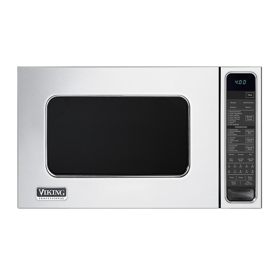
(VMOC205SS model shown)
In the interest of user-safety the oven should be restored to its original condition and only parts identical to those specified
should be used.
WARNING TO SERVICE PERSONNEL: Microwave ovens contain circuitry capable of producing very high voltage and
current. Contact with the following parts may result in a severe, possibly fatal, electrical shock. (Inverter unit that includes
High Voltage Capacitor, High Voltage Power Transformer, High Voltage Rectifier and Heat sink etc., and Magnetron, High
Voltage Harness etc..)
BEFORE SERVICING ...................................................................................................... INSIDE FRONT COVER
WARNING TO SERVICE PERSONNEL ................................................................................................................2
MICROWAVE MEASUREMENT PROCEDURE (Canada) ......................................................................................3
MICROWAVE MEASUREMENT PROCEDURE (USA) ..........................................................................................4
FOREWORD AND WARNING ................................................................................................................................5
PRODUCT SPECIFICATIONS ...............................................................................................................................6
GENERAL INFORMATION ...................................................................................................................................6
OPERATION .........................................................................................................................................................8
TROUBLESHOOTING GUIDE ............................................................................................................................. 14
TEST PROCEDURE ............................................................................................................................................ 16
TOUCH CONTROL PANEL ASSEMBLY ............................................................................................................. 23
COMPONENT REPLACEMENT AND ADJUSTMENT PROCEDURE .................................................................. 29
PICTORIAL DIAGRAM ........................................................................................................................................ 36
POWER UNIT CIRCUIT ....................................................................................................................................... 37
PRINTED WIRING BOARD ................................................................................................................................. 38
PARTS LIST ........................................................................................................................................................ 39
PACKING AND ACCESSORIES ......................................................................................................................... 44
Range Corporation
111 Front St., Greenwood, MS 38930
Tel: (888) 845-4641
SERVICE MANUAL
TABLE OF CONTENTS
MICROWAVE OVEN
DMOC205SS
MODELS
VMOC205SS
This document has been published to be used for after
sales service only.
The contents are subject to change without notice.
DMOC205SS
VMOC205SS
S14M227DMO205
Page
Advertisement
Table of Contents

Related Manuals for Viking DMOC205SS


Summary of Contents for Viking DMOC205SS
-
Page 1: Table Of Contents
PARTS LIST ... 39 PACKING AND ACCESSORIES ... 44 Range Corporation 111 Front St., Greenwood, MS 38930 Tel: (888) 845-4641 MICROWAVE OVEN DMOC205SS MODELS VMOC205SS TABLE OF CONTENTS This document has been published to be used for after sales service only. -
Page 2: Precautions To Be Observed Before And During Servicing To Avoid Possible Exposure To Excessive Microwave Energy
Before servicing an operative unit, perform a microwave emission check as per the Microwave Measure- ment Procedure outlined in this service manual. If microwave emissions level is in excess of the specified limit, contact Viking Service immediately @ 1-888-845-4641. If the unit operates with the door open, service person should (1) tell the user not to operate the oven and (2) contact VIKING, plus the Department Of Health, Canada and/or the Food and Drug Administration's Center for Devices and Radiological Health immediately. - Page 3 DMOC205SS VMOC205SS Notes...
-
Page 4: Warning To Service Personnel
DMOC205SS VMOC205SS WARNING TO SERVICE PERSONNEL Microwave ovens contain circuitry capable of pro- ducing very high voltage and current, contact with following parts may result in a severe, possibly fatal, electrical shock. (Example) High Voltage Capacitor, High Voltage Power Transformer, Magnetron, High Voltage Rectifier Assembly, High Voltage Harness etc.. -
Page 5: Microwave Measurement Procedure (Canada)
1) Operate the oven without a load and measure the leakage by the same method as the above test procedure " Leakage test with enclosure installed" 2. Make sure that the highest leakage should not exceed 5mW/cm NOTE: After servicing, record data on service invoice and microwave leakage report. C in the center of the oven cavity. DMOC205SS VMOC205SS... -
Page 6: Microwave Measurement Procedure (Usa)
DMOC205SS VMOC205SS MICROWAVE MEASUREMENT PROCEDURE (USA) A. Requirements: 1) Microwave leakage limit (Power density limit): The power density of microwave radiation emitted by a microwave oven should not exceed 1mW/cm at any point 5cm or more from the external surface of the oven, measured prior to acquisition by a purchaser, and thereafter (through the useful life of the oven), 5 mW/cm surface of the oven. -
Page 7: Foreword And Warning
MICROWAVE OVENS DMOC205SS VMOC205SS FOREWORD This Manual has been prepared to provide Viking Service Personnel with Operation and Service Information for the Viking Microwave Ovens, DMOC205SS, VMOC205SS. It is recommended that service personnel carefully study the entire text of this manual so that they will be qualified to render satisfactory customer service. -
Page 8: Product Specifications
DMOC205SS VMOC205SS ITEM Power Requirements Power Output Convection Power Output Case Dimensions Cooking Cavity Dimensions (1.5 Cubic Feet ) Control Complement Oven Cavity Light Safety Standard This oven is equipped with a three prong grounding plug. It must be plugged into a wall receptacle that is properly installed and grounded. -
Page 9: Oven Diagram
10. Lighted digital display. 11. Convection air openings. 12. Removable low rack. (Broiling trivet) 13. Removable low rack. (Baking rack) 14. Turntable motor shaft. 15. Power supply cord. Grounded 3-Pronged Plug Receptacle Box Grounding Pin 3-Pronged Receptacle TOUCH CONTROL PANEL VMOC205SS DMOC205SS VMOC205SS... -
Page 10: Operation
DMOC205SS VMOC205SS DESCRIPTION OF OPERATING SEQUENCE The following is a description of component functions during oven operation. OFF CONDITION Closing the door activates the door sensing switch and secondary interlock switch. (In this condition, the monitor switch contacts are opened.) When oven is plugged in, 117 volts A.C. - Page 11 When the food is cooked, water vapor is developed. DMOC205SS VMOC205SS MICROWAVE POWER = APPROX. 10% CONVECTION TEMPERATUE = 350°F (180°C)
- Page 12 DMOC205SS VMOC205SS The sensor “senses” the vapor and its resistance increases gradually. When the resistance reaches the value set according to the menu, supplementary cooking is started. The time of supplementary cooking is determined by experi- ment with each food category and inputted into the LSI.
-
Page 13: Schematic Diagram
SENSING AH SENSOR MISTOR SWITCH SWITCH N.O. (RY1) POWER TRANSFORMER COM. (RY3) COM. (RY2) N.O. (RY2) CAPACITOR 0.94µ N.O. (RY3) F-2 F-1 N.O. (RY1) POWER TRANSFORMER COM. (RY3) COM. (RY2) N.O. (RY2) CAPACITOR 0.94µ N.O. (RY3) F-2 F-1 DMOC205SS VMOC205SS... - Page 14 DMOC205SS VMOC205SS SCHEMATIC NOTE: CONDITION OF OVEN 1. DOOR CLOSED. 2. MIX COOKING PAD TOUCHED. 3. COOKING TIME PROGRAMMED. 4. “START” PAD TOUCHED. 5. RY2 AND RY3 WILL ALTERNATELY CLOSE. DURING COOK CYCLE. CONV. THERMAL NOISE FILTER CUT-OUT 117V 60Hz...
-
Page 15: Description And Function Of Components
The air heated by the heating element is circulated through the convection passage provided on the outer casing of the DMOC205SS VMOC205SS ο ο ο... -
Page 16: Troubleshooting Guide
DMOC205SS VMOC205SS oven cavity by means of the convection fan which is driven by the convection motor. It then enters the inside of the oven through the vent holes provided on the left side of the oven. Next, the hot air heats the food on the turntable and leaves the oven cavity through the vent in the center of the oven cavity left side wall. - Page 17 OVEN LAMP OR SOCKET Replace FAN MOTOR Replace TURNTABLE MOTOR Replace CONVECTION MOTOR Replace LOOSE WIRING Check SHORTED IN POWER CORD Check NO POWER AT OUTLET Check LOW VOLTAGE Check NOISE FILTER OFF CONDITION COOKING CONDITION DMOC205SS VMOC205SS (SENSOR (MICROWAVE) (CONVECTION) COOKING)
-
Page 18: Test Procedure
DMOC205SS VMOC205SS PROCEDURE LETTER MAGNETRON ASSEMBLY TEST HIGH VOLTAGES ARE PRESENT DURING THE COOK CYCLE, SO EXTREME CAUTION SHOULD BE OBSERVED. DISCHARGE THE HIGH VOLTAGE CAPACITOR BEFORE TOUCHING ANY OVEN COMPONENTS OR WIRING. To test for an open filament, isolate the magnetron from the high voltage circuit. A continuity check across the magnetron filament leads should indicate less than 1 ohm. - Page 19 An open thermal cut-out indicates overheating of the oven cavity. TEST PROCEDURES COMPONENT TEST N.C. COM. SCREW DRIVER ο ο F (130 C). If the thermal cut-out has operated under the normal DMOC205SS VMOC205SS MONITOR SWITCH PRIMARY OHMMETER INTERLOCK SWITCH ο ο F (150...
- Page 20 DMOC205SS VMOC205SS PROCEDURE LETTER MAGNETRON THERMAL CUT-OUT (on the waveguide) A continuity check across the thermal cut-out terminals should indicate a closed circuit unless the temperature of the thermal cut-out reaches approximately 257 An open thermal cut-out indicates overheating of the magnetron. Check for restricted air flow to the magnetron through the vent holes of the oven cavity, especially the cooling duct and cooling fan.
- Page 21 TEST PROCEDURES COMPONENT TEST INDICATION OF OHMMETER Open circuit. Short circuit. Short circuit. DMOC205SS VMOC205SS NOISE FILTER FUSE 20A NOISE SUPPRESSION COIL LINE CROSS CAPACITOR 0.22µF / AC 250V LINE BYPASS...
- Page 22 DMOC205SS VMOC205SS PROCEDURE LETTER KEY UNIT TEST If the display fails to clear when the STOP/CLEAR pad is depressed, first verify the flat ribbon cable is making good contact, verify that the door sensing switch (stop switch) operates properly; that is the contacts are closed when the door is closed and open when the door is open.
- Page 23 Check supply voltage and oven power cord. Power transformer or secondary circuit defective. Check and repair. *Insert jumper wire J1 and solder. *Insert the coil RCILF2003YAZZ between "c" and "d". Ω ± 10%). If ο ο F (35 DMOC205SS VMOC205SS CAUSE OR CORRECTION...
- Page 24 DMOC205SS VMOC205SS PROCEDURE LETTER When the AH sensor is defective (open or short), Error will appear in the display after 16 seconds cleaning time. If ERROR appears check sensor wire connections and/or AH sensor. NOTE: ERROR will appear if the door is opened or STOP/CLEAR pad is touched during first stage of sensor cooking.
-
Page 25: Touch Control Panel Assembly
Basically, a Fluorescent Display is triode having a cathode, a grid and an anode. Usually, the cathode of a Fluorescent Display is directly heated and the filament serves as cathode. The Fluorescent Display has 8-digits, 16-segments are used for displaying figures. DESCRIPTION OF LSI Description DMOC205SS VMOC205SS... - Page 26 DMOC205SS VMOC205SS Pin No. Signal AN5-AN3 Description Used for initial balancing of the bridge circuit (absolute humidity sensor). This input is an analog input terminal from the AH sensor circuit, and connected to the A/D converter built into the LSI.
- Page 27 P25. Signal similar to P27. When any one of G-4 line key on key matrix is touched, a corresponding signal will be input into P24. Description ß(60Hz) 16.7 msec. DMOC205SS VMOC205SS H : GND During cooking (Convection) H : GND...
- Page 28 DMOC205SS VMOC205SS Pin No. Signal 38-40 P22-P20 49-53 P07-P03 54-56 P02-P00 57-59 P37-P35 60-64 P34-P30 Description Segment data signals. The relation between signals and indicators are as follows: Signal Segment Signal Segment P23 ... P1 P17 ... P5 P22 ... P2 P16 ...
- Page 29 Absolute humidity vs, output voltage characterist C. Thermistor in closed vesssl S. Thermistor in open vessel Absolute humidity (g/m ) IC2(IZA495DR) 620k 300k 150k 37.4k 3.57k 3.32k 1.8k 360k VA : -15V VA : -15V VC : -5V DMOC205SS VMOC205SS (IC1)
- Page 30 DMOC205SS VMOC205SS 1. Precautions for Handling Electronic Components This unit uses CMOS LSI in the integral part of the circuits. When handling these parts, the following precautions should be strictly followed. CMOS LSI have extremely high impedance at its input and output terminals.
-
Page 31: Component Replacement And Adjustment Procedure
4. Remove the magnetron from the unit with care so the magnetron tube should not hit by any metal object around the tube. CAUTION: WHEN REPLACING THE MAGNETRON, BE BEFORE REMOVING OUTER CASE. SURE THE R.F. GASKET IS IN PLACE AND THE MAGNETRON MOUNTING SCREWS ARE TIGHTENED SECURELY. DMOC205SS VMOC205SS... - Page 32 DMOC205SS VMOC205SS HIGH VOLTAGE RECTIFIER ASSEMBLY REMOVAL 1. Disconnect oven from power supply and remove outer case. 2. Discharge the high voltage capacitor. 3. Remove one (1) screw holding the rectifier assembly to the capacitor holder. 4. Disconnect the rectifier assembly from the capacitor HIGH VOLTAGE CAPACITOR REMOVAL 1.
- Page 33 3) Now, the fan blade will be free. CAUTION: * Do not use this removed fan blade again because the hole (for shaft) of it may become bigger than a standard one. DMOC205SS VMOC205SS Long nose plier Heating element Heating element...
- Page 34 DMOC205SS VMOC205SS 16.Remove the two (2) screws and nuts holding the fan motor to the fan duct. 17.Now, the fan motor is free. INSTALLATION 1. Install the fan motor to the fan duct with the two (2) screws and nuts.
- Page 35 Note: When the individual parts are replaced, refer to "Door Disassembly". 6. On re-installing door, insert the upper oven hinge into the door hinge pin. Then while holding door in place. DMOC205SS VMOC205SS LATCH HOOK THIRD DOOR SWITCH DOOR SENSING...
-
Page 36: Door Disassembly
DMOC205SS VMOC205SS 7. Make sure the door is parallel with oven face lines (left and upper side lines) and door latch heads pass through latch holes correctly. 8. Insert the lower oven hinge into oven cavity bottom flange and then engaged the door hinge pin. Then secure the lower oven hinge firmly with tree (3) mounting screws. -
Page 37: Microwave Measurement Procedure
1. Operate the oven without a load and mesure the leakage by the same method as the above test procedure “A. Test Enclosure Installed”. 2. Make sure that the highest leakage should not exceed 5mW/cm Note: Do not perform this test for extended periods. DMOC205SS VMOC205SS... -
Page 38: Pictorial Diagram
DMOC205SS VMOC205SS... -
Page 39: Power Unit Circuit
0.1µ/50v HZ16-1 SP40 1/2w 1000µ/35v 0.1µ/50v 10G471K VRS1 (J1) 100k 100k 100k R100 IXA103DR (J7) 6.8k (J5) (J3) (J6) (J4) (J2) 0.1µ/50v 10µ/35v 0.1µ/50v 3.3k 3.3k 3.3k 3.3k 3.3k 3.3k 3.3k 3.3k 3.3k 3.3k 3.3k 3.3k 3.3kF 220F DMOC205SS VMOC205SS... -
Page 40: Printed Wiring Board
DMOC205SS VMOC205SS (C81) R86(J8) (C80) (R45) (C45) (CN - D) (R47) (R48) (R49) (C46) (C47) (J7) (J5) (J3) (J2) (J4) (J6) CONV HEATER COM Figure S-3. Printed Wiring Board... -
Page 41: Parts List
Turntable motor cover 2-12 PCOVPA171WRP0 CSA barrier 3- 1 DPWBFC189WRUZ Control unit 3- 2 FPNLCB458MRK0 Control panel frame with key unit (DMOC205SS) 3- 2 FPNLCB459MRK0 Control panel frame with key unit (VMOC205SS) 3- 2-1 FUNTKA393WRE0 Key unit (DMOC205SS) 3- 2-1 FUNTKA394WRE0... - Page 42 Noise unit angle Cushion Damper duct cushion Cushion Magnetron air guide Thermal protection sheet Thermo cover DOOR PARTS Door panel assembly complete (DMOC205SS) Door panel assembly complete (VMOC205SS) Door panel Choke cover Latch angle Latch head Latch head spring Thermal plate U Thermal plate R Screw;...
- Page 43 Screw; 6mm x 14mm 7-24 XOTSD40P12000 Screw; 4mm x 12mm 7-25 XFPSD30P08000 Screw; 3mm x 7-26 XNESD40-32000 Nut; 4mm x 3.2mm 7-27 XNEUW40-32000 Nut; 4mm x 3.2mm 7-28 XWSUW40-10000 Washer; 4mm x 1 mm 7-29 LX-CZA070WRE0 Screw; UL DESCRIPTION DMOC205SS VMOC205SS Q'TY CODE...
- Page 44 DMOC205SS VMOC205SS OVEN AND CABINET PARTS...
- Page 45 CONTROL PANEL PARTS 6-11 3-2-1 3-2-3 DOOR PARTS MISCELLANEOUS 7-24 3-2-2 5-10 5-11 Actual wire harness may be different than illustration. 7-24 6-10 DMOC205SS VMOC205SS...
-
Page 46: Packing And Accessories
DMOC205SS VMOC205SS PACKING AND ACCESSORIES TRAY HOLDER 4-3 TURNTABLE TRAY 6-9 OPERATION MANUAL 6-14 S/S CLEANING INSTRUCTIONS 6-15 COOK BOOK 4-2 TURNTABLE SUPPORT DOOR PROTECTION SHEET MICROWAVE OVEN TRAY PACKING FOAM Not replaceable items. TOP PAD ASSEMBLY PLASTIC BAG BOTTOM PAD ASSEMBLY... - Page 47 DMOC205SS VMOC205SS NOTES:...
- Page 48 DMOC205SS VMOC205SS COPYRIGHT © 2004 BY VIKING ALL RIGHTS RESERVED No part of this publication may be reproduced, stored in a retrieval system, or transmitted in any form or by any means, electronic, mechanical, photocopying, recording, or otherwise, without prior written permission of the publisher.