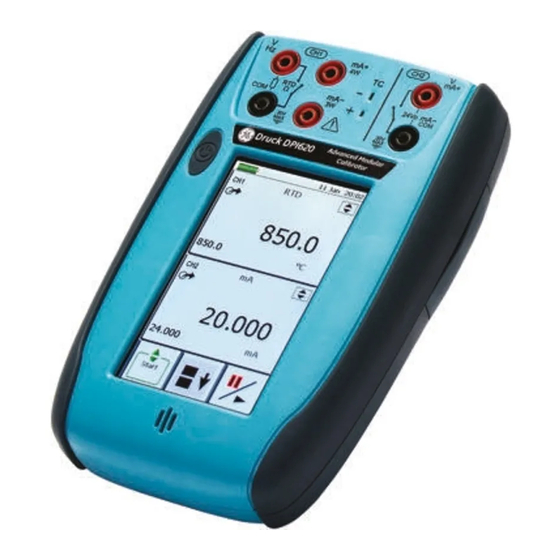
GE Druck DPI 620 User Manual
Advanced modular calibrator
Hide thumbs
Also See for Druck DPI 620:
- Safety and quick reference manual (12 pages) ,
- User manual (248 pages)

Related Manuals for GE Druck DPI 620


Summary of Contents for GE Druck DPI 620
- Page 1 Sensing & Inspection Technologies Druck DPI 620 advanced modular calibrator user manual - K0449...
-
Page 2: Trademarks
Issue 1 Quick reference data A1.1 DPI 620: Channel 1 (CH1) Measure (M) / Source (S) / Power (P) ±30 V (M) ±55 mA (M) 0 to 12 V (S) 0 to 24 mA (S) ±2000 mV (M) 8 RTDs (M/S): Pt1000, Pt500, Pt200, Pt100(385), 0 to 2000 mV (S) Pt50, D 100, Ni 100, Ni 120 0 to 4000 : (M/S) -
Page 3: Safety
(earth). • To prevent electrical shocks, use only the GE specified AC probe (Part: IO620-AC) to measure AC voltages that are more than 20 Vrms (maximum: 300 Vrms). Attach it to the specified connections only. - Page 4 Issue 1 • Pressurized gases and fluids are dangerous. Before you attach or disconnect pressure equipment, safely release all the pressure. • To prevent a dangerous release of pressure, make sure that all the related pipes, hoses and equipment have the correct pressure rating, are safe to use and are correctly attached.
-
Page 5: Overview
Issue 1 Overview The advanced modular calibrator (AMC) is part of a set of hand-held modules that you can quickly put together to include a wide range of calibrator functions. Advanced modular calibrator, DPI 620 (this user manual): This is a battery-powered instrument for electrical measure and source operations and HART®... - Page 6 Issue 1 Other accessories and options: For part numbers (P/N), refer to Section 1.4 (Accessories). Summary of This table gives a summary of the available functions with the DPI 620 calibrator. functions DPI 620 - Calibrator functions Function Easy to read liquid crystal display (LCD) in colour No keys: the touch-screen has large buttons for finger operation.
-
Page 7: About This Manual
Issue 1 DPI 620 - Calibrator functions (Continued) Function ® HART (Highway Addressable Remote Transducer) communications software to set up and calibrate devices that use the HART field communications protocol. Other functions: Hold, maximum/minimum/average, filter, tare, adjustable backlight, adjustable volume for the sound port, alarm indication (on the display and from the sound port), automatic power off. - Page 8 Issue 1 viii About this manual K0449 - [EN] English...
-
Page 9: Table Of Contents
Issue 1 Table of Contents Quick reference data ............ii Trademarks . - Page 10 Issue 1 2.10 Menu sequence ........... . . 2-7 2.10.1 Procedure to set the basic operations: .
- Page 11 Issue 1 Chapter 4: Pressure indicator operation (MC 620) 4.1 Introduction ............4-1 4.2 Parts and assembly .
- Page 12 Issue 1 8.5 Start HART menu operations ......... . 8-8 8.5.1 HART menu - Information (Sensor, Hardware, Settings) .
-
Page 13: Chapter 1: Instrument Parts, Accessories And Options
(COM = Common) Note: * You can measure an AC voltage (maximum: 20 Vrms) without the GE specified AC probe (P/N IO620-AC). If it is more than 20Vrms, you must use the AC probe (maximum: 300 Vrms) in CH1 connectors V/Hz and COM; see Section 3.2.5. - Page 14 Issue 1 : USB type A connector for connections to external peripherals (USB flash memory or optional external modules). : USB mini Type B connector for communication with a computer. The optional USB mini Type B cable also supplies power to the instrument; see Section 2.4 (Power options).
-
Page 15: The Display
Issue 1 1.3 The display This is a LCD with a colour display and a touch-screen. To make a selection, lightly tap on the applicable display area with a finger; see Section 2.9 (Display operation). Status bar: This includes: a. Battery indicator b. -
Page 16: Accessories
Issue 1 1.4 Accessories 1. IO620-PSU. DC power supply 2. IO620-BATTERY. Li-Polymer battery 3. 209-539. Set of six electrical test leads 4. K0454. Safety and quick reference guide 5. UD-0002. CD with the user manual Figure 1-7: Accessories included 6. IO620-AC. AC probe that attaches to the specified calibrator sockets (see Section 3.2.5) and measures... - Page 17 Issue 1 16. Pressure modules (PM 620); refer to the datasheet. 17. Pneumatic hose kit rated to 400 bar (5800 psi) with “Quick fit” connectors for the test port. IO620-HOSE-P1: 1 metre (| 39”) IO620-HOSE-P2: 2 metre (| 78”) 18. Hydraulic hose kit rated to 1000 bar (15000 psi) with “Quick fit”...
- Page 18 Issue 1 1-6 Instrument parts, accessories and options K0449 - [EN] English...
-
Page 19: Chapter 2: Prepare The Instrument
Chapter 2: Prepare the instrument 2.1 Introduction This chapter gives a description of these items: • the initial checks and procedures • the available power options • the battery and related procedures (install and charge) • the start up procedures •... -
Page 20: The Battery
For operating conditions, see Table 10-1. • To prevent an explosion or fire, use only the GE specified battery, power supply and battery charger. • To prevent battery leakage or heat generation, only use the battery charger and power supply in the temperature range 0 to 40°C (32 to 104°F). -
Page 21: Charge The Battery
2.6 The DC power WARNING supply • To prevent an explosion or fire, use only the GE specified battery, power supply and battery charger. • To prevent battery leakage or heat generation, only use the battery charger and power supply in the temperature range 0 to 40°C (32 to 104°F). -
Page 22: The Usb Power Supply
Issue 1 If there is a battery, internal safety circuits control the charge cycle. If you are using the instrument, this increases the time to charge the battery. Step Procedure Attach the applicable socket adaptor to the DC power supply. On the right-hand side of the instrument (Figure 1-3), use the rubber recess to pull down... -
Page 23: Display Operation
Issue 1 2.9 Display operation This instrument has a touch-screen. To make a selection, lightly tap on the applicable display area (window, button, option) with a finger. Caution: To prevent damage to the display, do not use sharp objects on the touch-screen. The number of windows you see on the display is set by the number of task selections and external modules you are working with (maximum: 6);... -
Page 24: Enter Text
Issue 1 2.9.3 Enter text There are alphanumeric keypad displays for these items: • Captions; see Section 2.10.4 (maximum: 15 characters; all characters permitted) • Filenames (maximum: 10 characters; no special characters) 1. Tap in the applicable characters. 2. To accept the data and go back to the previous display, tap on the completed text in the data entry box. -
Page 25: Menu Sequence
Issue 1 2.10 Menu sequence Section 2.10.1 Section 2.10.2 Chapter 6 † Chapter 7 Section 2.12 † Touch Screen lets you calibrate and re-centre the screen. Normally, this is only necessary for versions with the Windows CE operating system. Task* Channel Select Settings... -
Page 26: Procedure To Set The Basic Operations
Issue 1 2.10.1 Procedure to set the basic operations: Description Configuration Sets the power off automatically after the specified Timeout period. To save the battery power, set this to On. Status: On or Off Timeout: 00:02:00 to 01:00:00 hours:minutes:seconds (hh:mm:ss) Sets the backlight. -
Page 27: Procedures To Make Task Selections
Issue 1 2.10.3 Procedures to make Task selections When you first use the calibrator, there are default measure and source functions on the display: • CH1 settings: RTD source, RTD type is PT100, scale is °C; Automation is Nudge; see Chapter •... -
Page 28: Set A Function
Issue 1 • If applicable, set a Utility for the function: item Continued a. Max/Min/Avg; see Section 2.10.6 b. Switch Test: CH1, P1, P2 and IDOS functions use the CH2 switch connections; CH2 functions use the CH1 switch connections. See Chapter 3 c. -
Page 29: Set The Units
Issue 1 2.10.5 Set the units If a function has alternative units, you can set another unit. If there are no alternatives, the area is shown grey. Task Settings Channel Settings Channel Settings Task Settings 2.10.6 Set up a utility: Maximum/Minimum/Average example This example shows the sequence to set the Max/Min/Avg utility. -
Page 30: Measure And Source Operations
Issue 1 2.11 Measure and When you have set the measure and source functions that you want to see on the display (see Section 2.10.3), you can source operations complete these procedures: • If necessary, change the Process for the CH1 and/or CH2 measure functions: item This includes: Tare, Alarm, Filter, Flow, Scaling;... -
Page 31: Set The Process Options (Measure)
Issue 1 c. Pressure operations with a PV 62x pressure station (refer to the user manual - K0457) 2.11.1 Set the Process options (measure Note: Section 2.9 (Display operation) shows how to set and change the values on the display. Tare Use Tare to set a temporary value for zero. - Page 32 Issue 1 Filter: You can set the Band and the Time Constant for the low pass filter: Set On or Off Set the band (%FS). See Definitions Set the time constant. See Definitions Previous: Back one display Home: Back to start Definitions Band: The filter compares each new value with the...
-
Page 33: Set The Automation Options (Source)
Issue 1 Scaling: Set On or Off Set a scale for Point 1 and Point 2 Set a label name Previous: Back one display Home: Back to start 2.11.2 Set the Automation options (source Note: Section 2.9 (Display operation) shows how to set and change the values on the display. -
Page 34: Set The Observed Settings (Source)
Issue 1 Percent Step Description Process: Percent Step; Values to set: Low, High, Step Size (%FS), Dwell, Auto Repeat (On/Off) Use these buttons to change the value manually by the specified Step Size. Use the start and stop buttons to change the value automatically by the specified Step Size. -
Page 35: Advanced: Calibration Options
Issue 1 You can use the Observed function to make a manual record of the readings you can see on another instrument. For example, you can make a permanent record of the readings with Data Logging (Chapter Settings These settings are available: Description Values to set: Units (enter a name for the units) - Page 36 Issue 1 • Set the next calibration date and/or set the Notification option. If Notification is On and your calibration is overdue, you get a “Calibration due ... ” message at the end of the power on sequence. Menu to upgrade the To use most up to date software and firmware on your DPI 620 DPI 620 software and calibrator, visit our website:...
-
Page 37: Advanced Setup Options
Issue 1 2.12.2 Advanced Setup options Use this menu to save and recall personal settings, instrument calibration settings and other standard instrument operations. Save: When you have set up the functions you want to see on the display (Section 2.10.3) and all the measure and source operations (Section 2.11), save your settings to a file. - Page 38 Issue 1 2-20 Prepare the instrument K0449 - [EN] English...
-
Page 39: Chapter 3: Electrical And Idos Operations
Chapter 3: Electrical and IDOS operations 3.1 Introduction This section gives examples of how to connect and use the instrument for these operations: • to measure and source electrical values • to measure the pressure with an IDOS module Before you start: •... -
Page 40: Example Procedure: Measure Or Source Current
Issue 1 • If necessary, change the Process for the CH1 and/or CH2 measure functions: item This includes: Tare, Alarm, Filter, Flow, Scaling; see Section 2.11.1. There are more optional Settings for the TC, Frequency, and RTD functions. • If necessary, change the Automation options for the CH1 and/or CH2 source functions: item This includes: Nudge, Span Check, Percent Step, Defined Step, Ramp;... -
Page 41: Example Procedure: Measure Dc Voltage
3.2.4 Example procedure: Measure AC voltage (CH1), 0 to 20 Vrms only WARNING To prevent electrical shocks, use only the GE specified AC probe (Part: IO620-AC) to measure AC voltages that are more than 20 Vrms (maximum: 300 Vrms). Attach it to the specified connections only. -
Page 42: Example Procedure: Measure Ac Voltage (Ch1) With The Ac Probe
3.2.5 Example procedure: Measure AC voltage (CH1) with the AC probe WARNING To prevent electrical shocks, use only the GE specified AC probe (Part: IO620-AC) to measure AC voltages that are more than 20 Vrms (maximum: 300 Vrms). Attach it to the specified connections only. -
Page 43: Example Procedure: Source Dc Voltage (Ch1)
Issue 1 3.2.6 Example procedure: Source DC voltage (CH1) These examples (A and B) show Channel 1 (CH1) set up to source a DC voltage. Source DC volts on channel 1 (CH1) Range: 0 to 12 V (DC) Automation: Nudge (Section 2.11.2) Source DC millivolts on... -
Page 44: Example Procedure: Measure Or Source Frequency Signals
Issue 1 1. Set the applicable software options; see Section 3.2.1 (Procedure overview). 2. Complete the electrical connections and continue with the measure or source operation. 3. Source only (Automation): Set the applicable output value; Section 2.11.2. 3.2.8 Example procedure: Measure or source frequency signals These examples (A and B) show Channel 1 (CH1) set up to measure or source a frequency. -
Page 45: Example Procedure: Measure Or Simulate An Rtd (Or Resistance)
Issue 1 2. Complete the electrical connections. 3. If necessary change the Source Settings and continue with source operation. Values to set: Waveform (Square, Triangle, Sine); Amplitude (Amplitude value) 4. Automation: Set the applicable output value; see Section 2.11.2. 3.2.9 Example procedure: Measure or simulate an RTD (or Resistance) These examples (A and B) show Channel 1 (CH1) set up to measure or simulate an RTD. -
Page 46: Example Procedure: Measure Or Simulate A Thermocouple (Or Tc Mv)
Issue 1 Values to set: RTD Type (Set the applicable RTD); see Table A1 (front cover) for the available options. Example B 1. Set the applicable software options; see Section 3.2.1 (Procedure overview). 2. Complete the electrical connections. 3. If necessary change the Source Settings and continue with source operation. -
Page 47: Example Procedure: Switch Test
Issue 1 3. If necessary change the Settings and continue with the measure operation. Values to set: TC Type (Set the applicable TC) CJ compensation (Mode: Automatic/Manual). Automatic uses the internal cold junction. Use Manual mode when you want to use an external cold junction. CJ Value. -
Page 48: Measure Pressure: Idos Option
Issue 1 1. Set the applicable software options; see Section 3.2.1 (Procedure overview). This example shows one function: • Thermocouple (TC) is set to source a temperature. The Utility is set to Switch Test. The Automation is set to Ramp; Section 2.11.2. -
Page 49: Assembly Instructions
Issue 1 3.3.1 Assembly instructions Step Procedure Attach one end of the adaptor (IO620-IDOS-USB) to the applicable IDOS module. On the right-hand side of the instrument (Figure 1-3), use the rubber recess to pull down the cover for the connections. Push the Type A end of the adaptor (IO620-IDOS-USB) into the USB socket on the instrument. -
Page 50: Example Procedure: Measure Pressure With An Idos Module
Issue 1 c. Leak Test. The procedure is the same for an IDOS module or for a MC 620/PM 620 assembly; see Section 4.4.2. • If necessary, change the Settings for the IDOS function: item a. Process (Tare, Alarm, Filter, Flow, Scaling); Section 2.11.1 b. -
Page 51: Error Indications
Issue 1 3.4 Error indications If the display shows <<<< (under range) or >>>> (over range): • Make sure that the range is correct. • Make sure that all the related equipment and connections are serviceable. <<<<< Under range: The display shows this symbol for this condition: Reading <... - Page 52 Issue 1 3-14 Electrical and IDOS operations K0449 - [EN] English...
-
Page 53: Chapter 4: Pressure Indicator Operation (Mc 620)
Chapter 4: Pressure indicator operation (MC 620) 4.1 Introduction This section gives examples of how to connect and use the instrument to measure pressure with the module carrier (MC 620) and the applicable pressure modules (PM 620). To measure pressure with the IDOS UPM, refer to Chapter To make a fully integrated pressure calibrator instrument with one of the three pressure stations, refer to the user manual for... -
Page 54: Assembly Instructions
Issue 1 4.2.1 Assembly instructions Step Procedure Align the two slots (a) on the calibrator with the two posts (b) on the module carrier. When the posts are fully engaged in the slots, tighten the two screws until they are hand tight. Attach one or two PM 620 modules with the correct range and type. - Page 55 Issue 1 Step Procedure Re-attach the adaptor to the MC 620 carrier and tighten it until it is hand tight only. 4.4 Measure When the pressure indicator assembly is complete (Section 4.2.1), use the menus to set up the necessary pressure operations.
-
Page 56: Measure Pressure
Issue 1 • When all the software selections are complete, make the applicable pressure and electrical connections. Examples: Measure pressure (Section 4.4.4) 4.4.2 Set up a Leak Test 1) Set the Utility Set the Utility to Leak Test (Section 2.10.6). 2) Set the Leak Test When you have set the Utility to Leak Test, you can set these options... -
Page 57: Set The Pressure Module To Zero
Issue 1 4.4.3 Set the pressure module to zero Use this option to write a new zero pressure value to the pressure module you are using. The sensor adjustment is permitted if it obeys this condition: Adjustment d 10% FS positive pressure value (for the Sensor) Note: To make a temporary adjustment for zero, you can use the Tare function;... -
Page 58: Error Indications
Issue 1 2. Set the applicable software options; see Section 4.4.1 (Procedure overview). This example shows two pressure functions: • Pressure functions P1 and P2 are set up. 3. To attach the external equipment, see Section 4.3.1. 4.5 Error indications If the display shows <<<<... -
Page 59: Chapter 5: Instrument Communications
Chapter 5: Instrument communications 5.1 Introduction This chapter gives a description of these items: • the procedures to connect the instrument to a computer with the optional USB mini Type B cable For a full list of optional accessories, refer to Section 1.4. - Page 60 Issue 1 5-2 Instrument communications K0449 - [EN] English...
-
Page 61: Chapter 6: Datalog Operation
Chapter 6: Datalog operation 6.1 Introduction This section gives examples of how to log measurements with time and date over a set time period or on a key press. Logged data is stored in a user defined file. The instrument logs all the tasks currently enabled. - Page 62 Issue 1 Recall Log Playback Filename recalls data by filename from the list. File details shows file name, start time and number of points. Start begins playback of the selected file by pressing the Pause/Play key. Press and hold the Pause/Play key for at least two seconds to reverse sequence.
-
Page 63: Data Logging
Issue 1 6.3 Data Logging To data log: To log measurements made by the instrument, set the required tasks in Task Settings. Select Configuration and select Data Logging. Select Filename and enter a name using the three-page screen alpha/numeric key-pad. Select Trigger and either a time (Periodic) or key press (play/pause). - Page 64 Issue 1 6-4 Datalog operation K0449 - [EN] English...
-
Page 65: Chapter 7: Documenting Functions
Chapter 7: Documenting functions 7.1 Introduction This section gives examples of the documenting functions available with the DPI 620 calibrator. There are two options: Analysis (Section 7.2): This function lets you compare the data from two Channels on the DPI 620 calibrator: the device under test (DUT) and a reference instrument. -
Page 66: Run A Procedure
Issue 1 Input and Reference Channel type : Input or Reference options Scaling (Input only): Values for Reference High and Low and Input High and Low. This sets the scale for the Analysis function. Error Type (Input only): % Span or % Rdg (Reading) Linearity (Input only): Linear or Square Root Tolerance... -
Page 67: Sequence To Upload And Download File
Issue 1 7.3.1 Sequence to upload and download file Step Procedure P/N IO620-USB-RS232. Connect the USB Type A connector to the DPI 620 calibrator; see Chapter Connect the RS232 to the serial communications port on the computer that has Intecal installed; see Chapter Use Intecal to set up the Procedure and create a Work Order for the Device. - Page 68 Issue 1 7-4 Documenting functions K0449 - [EN] English...
-
Page 69: Chapter 8: Hart Device Operations
® Chapter 8: HART device operations 8.1 Introduction You can use the DPI 620 calibrator to communicate with devices that use the HART protocol: • The Universal and Common Practice commands specified in HART revision 5 to 7. This section includes procedures to use the HART functions available in the calibrator. -
Page 70: Available Hart Commands
Issue 1 8.3 Available HART This is a list of the commands that are available with the DPI 620 calibrator: commands Note: HART revision 5 field devices do not support some of these commands. Command name Command Menu Type and number revision level Return device ID, hardware/firmware version,... - Page 71 Issue 1 Command name Command Menu Type and number revision level Get extended status info Hart settings menu Common - 5 Write primary variable transducer serial number Hart Sensor Info Common - 5 Read dynamic variable assignments. Advanced device Common - 5 menu Write dynamic variable assignments Advanced device...
-
Page 72: Hart Connections
Issue 1 Command name Command Menu Type and number revision level Get measurand classification Advanced device Universal - 6 menu Read device variable trim points Trim Menu Common - 6 Read device variable trim guidelines Trim Menu Common - 6 Write device variable trim point Trim Menu Common - 6... -
Page 73: External Loop Power
Issue 1 2. Set the HART Resistor in the Advanced menu: Home display Set to “On” Section 2.9 3. Complete the electrical connections and continue with the HART menu operation; see Section 8.5. 8.4.2 External loop power In this example, there is an external power supply. Measure current on channel 2 (CH2) Range: ±55 mA... -
Page 74: Communicator Attached To A Network
Issue 1 2. Set the HART Resistor in the Advanced menu: Home display Set to On Section 2.9 3. Complete the electrical connections and continue with the HART menu operation; see Section 8.5. 8.4.3 Communicator attached to a network In this example, the calibrator connects directly to a network. There must be a 250: resistor in series with the loop power supply and the HART device. - Page 75 Issue 1 2. If necessary, set the HART Resistor in the Advanced menu to Off: Home display Set to Off Section 2.9 3. Complete the electrical connections and continue with the HART menu operation; see Section 8.5. ® [EN] English - K0449 HART device operations 8-7...
-
Page 76: Start Hart Menu Operations
Issue 1 8.5 Start HART menu When the power supply connections are complete, you can do a search for the applicable HART device and start the operations communications process. You use the same sequence of steps for all the power supply options: 2: Select 3 to 5: Set the search Search... -
Page 77: Hart Menu - Information (Advanced, Clone)
Issue 1 8.5.2 HART menu - Information (Advanced, Clone) Section 8.5.1 Example procedure: Clone The Clone function lets you copy the parameters from one field device to another of the same type and range. 1. Attach the first device with the necessary parameters and start communications (Section 8.5). -
Page 78: Hart Menu - Calibrate And Loop Test
Issue 1 8.5.3 HART menu - Calibrate and Loop Test Example procedure: Loop test 4: Actual value = 4.0123 5: HART menu 6: Calibrate 7: Trims 1: Loop Test = On 2: Test Value = 4.000 mA 3: Go to Home display 8: Enter Trim Zero = 4.0123 The loop current is set to 4.000 mA but the actual loop current... -
Page 79: Chapter 9: Maintenance Procedures
Chapter 9: Maintenance procedures 9.1 Introduction This section gives procedures to maintain the unit in a good condition. Return the instrument to the manufacturer or an approved service agent for all repairs. Do not dispose of this product as household waste. Use an approved organisation that collects and/or recycles waste electrical and electronic equipment. - Page 80 Issue 1 9-2 Maintenance procedures K0449 - [EN] English...
-
Page 81: Chapter 10: General Specification
(SEP) Approved CE Marked Battery power Lithium-Polymer battery (GE Part number: 191-356) Capacity: 5040 mAh (minimum), 5280 mAh (typical); Nominal voltage: 3.7 V. Charge temperature: 0 to 40°C (32 to 104°F) When the instrument senses the temperature is outside this range, it stops charging. - Page 82 Issue 1 10-2 General specification K0449 - [EN] English...
- Page 83 Customer service Visit our web site: www.gesensinginspection.com...