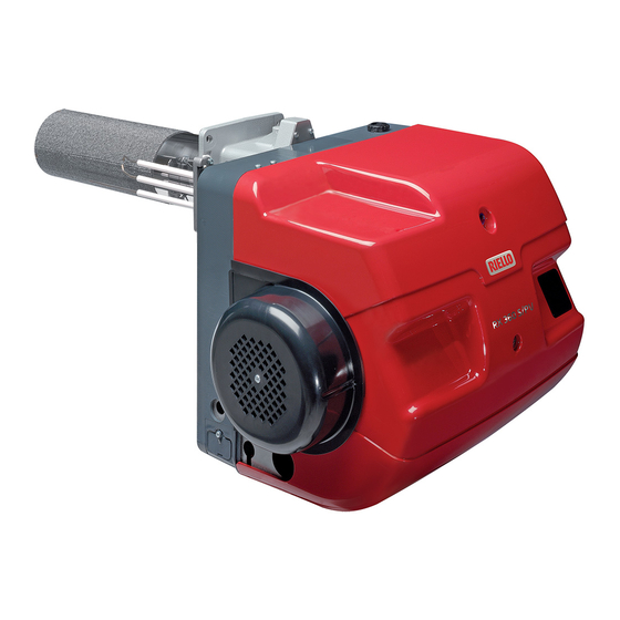
Riello RX 150 S/PV Installation, Use And Maintenance Instructions
Premix gas burner
Hide thumbs
Also See for RX 150 S/PV:
- Installation, use and maintenance instructions (50 pages) ,
- Installation, use and maintenance instructions (76 pages)

Related Manuals for Riello RX 150 S/PV


Summary of Contents for Riello RX 150 S/PV
- Page 1 Installation, use and maintenance instructions Premix gas burner Modulating operation CODE MODEL TYPE 20139726 RX 150 S/PV 904T2 20151674 (1) -05/2018...
- Page 2 Translation of the original instructions...
-
Page 3: Table Of Contents
Boring the boiler plate ............................... 18 5.5.2 Head length ................................18 Position of probe and electrode (RX 150 S/PV) ......................19 Securing the burner to the boiler (RX 150 S/PV) ...................... 19 Fuel supply ................................20 Gas valve adjustment..............................21 5.10 Electrical wiring ................................. - Page 4 Contents 7.2.2 Safety test - with gas feeding closed .........................31 7.2.3 Checking and cleaning...............................31 7.2.4 Safety components ..............................33 Opening and closing the burner ..........................33 Recommended preventive maintenance programme ....................34 Operation, indications, diagnostic ............................35 Control sequence in the event of a fault ........................35 Error code list with operation via the control box control panel..................36 Resetting of burner control............................37 8.3.1...
-
Page 5: Declarations
Electromagnetic Compatibility Quality is ensured by means of an ISO 9001:2015 certified quality and management system. Legnago, 01.12.2015 General Manager Research and Development Director RIELLO S.p.A. - Burners Department RIELLO S.p.A. - Burners Department Eng. U. Ferretti Eng. F. Comencini 20151674... -
Page 6: Information And General Warnings
Information and general warnings Information and general warnings Information about the instruction manual 2.1.1 Introduction WARNING: MOVING PARTS The instruction manual supplied with the burner: This symbol indicates that you must keep limbs is an integral and essential part of the product and must not away from moving mechanical parts;... -
Page 7: Delivery Of The System And The Instruction Manual
Information and general warnings 2.1.4 Delivery of the system and the instruction The system supplier must carefully inform the user about: – the use of the system; manual – any further tests that may be required before activating the When the system is delivered, it is important that: system;... -
Page 8: Safety And Prevention
Safety and prevention Safety and prevention Background The burners have been designed and built in compliance with which the burner has been regulated, the pressurisation of the current regulations and directives, applying the known technical combustion chamber, the dimensions of the combustion cham- rules of safety and envisaging all the potential danger situations. -
Page 9: Technical Description Of The Burner
Technical description of the burner Models available Designation Voltage Code External modulation (*) RX 150 S/PV 230V - 50-60 Hz 20139726 3 points TC = Supplied combustion head TL = Long combustion head version (*) FACTORY SETTING. To change the external modulation parameter it is necessary to access the password-protected list of parameters using the AZL 21... -
Page 10: Technical Data
Technical description of the burner Technical data Model RX 150 S/PV Type 904T4 Head assembly Supplied with head assembled Power min - max 25-145 Delivery min - max Mcal/h 21.5-124.7 Fuels Natural gas: G20 (methane), G25 - LPG: (G31)(*) Supply pressure... -
Page 11: Maximum Dimensions
The maximum dimensions of the burner are given in Fig. 1. Bear in mind that, in order to inspect the combustion head, the burner must be removed from the boiler door. 20144071 Fig. 1 RX 150 S/PV Tab. C RX 150 S/PV Tab. D Fig. 2... -
Page 12: Burner Description
Technical description of the burner Burner description 20144072 Fig. 3 Reset button Burner lockout may occur. Control box CONTROL BOX LOCKOUT: Gas valve The lockout signal is shown on the control box dis- Air/gas mixer in intake circuit WARNING play with “LOC” and the error code. Flange release by pressing the push-button 1)(Fig. -
Page 13: Burner Controls (Lme71
The LME71... are safety devices! Avoid opening WARNING or modifying it, or forcing its operation. Riello S.p.A. cannot assume any responsibility for damage resulting from unauthorised interven- tions! Also the safety notes contained in other chapters of this document must be respected! The installation and operation of the machine should be carried out only by qualified personnel. - Page 14 Technical description of the burner Installation notes Description of displays and buttons Arrange the high voltage ignition cables separately, as far as possible from the control box and the other cables. Do not confuse the powered conductors with the neutral ones.
- Page 15 Technical description of the burner Technical data Burner controls Mains voltage AC 230 V Mains frequency 50 / 60 Hz +- 6% LME71... Power absorption <10 W, normally Primary external fuse Max. 6.3 A (slow) Safety class I, with components in compliance with II and III, ac- cording to DIN EN 60730-1 "Input"...
- Page 16 Technical description of the burner Program sequence Standby Startup Operation Shutdown Valve proving if parameter P241 =1 (ON) Can be parameterized t11 t10 t12 t3 t3n t11 t8 td4 td1 td3 td2 Phase number oP: xx (actual load in %) 242 243 244 245 Operating unit parameter number LED permanent...
- Page 17 Technical description of the burner Key Fig. 7: Times Alarm device Safety time Standby time Auxiliary output Pre-purging time Lead connection Spark pre-ignition time Post-ignition time (P257 +0.3 seconds) Reset button (info button) (EK1) Interval: end of safety time - fuel valve 1 ON /reset (depending on Interval: end of safety time - fuel valve 2 ON...
-
Page 18: Indication Of The Diagnostic Mode
Technical description of the burner Phases key (Fig. 7 on page 14): 4.7.1 Indication of the diagnostic mode Phase The reset button (info button) is the key element Function number for resetting the burner control and activating/de- activating the diagnostic functions. Switching off phase lockout Stand-by, awaiting heat request The multi-colour indicator lamp is the key indica-... -
Page 19: Installation
After removing all the packaging, check the integ- rity of the contents. In the event of doubt, do not use the burner; contact the supplier. 2R 3R CAUTION RIELLO S.p.A. / I-37045 Legnago(VR) cod. xxxxxxxx The packaging elements (wooden cage or card- ..20122363 Fig. 8 board box, nails, clips, plastic bags, etc.) must not... -
Page 20: Operating Position
The burners cannot be used on flame inversion RX 150 S/PV 45° boilers. Tab. K WARNING It is possible to insert a protective device made of refractory material between the combustion head and the boiler refractory. -
Page 21: Position Of Probe And Electrode (Rx 150 S/Pv)
20122373 Probe Fig. 11 Securing the burner to the boiler (RX 150 S/PV) For the installation proceed as follows: Fix the burner 1) to the door of the boiler 2) putting the insu- lating gasket 3) in between (Fig. 12). -
Page 22: Fuel Supply
Installation Fuel supply The burners are teamed with one-piece pneumatic proportioning Explosion danger due to fuel leaks in the pres- gas valves, via which the amount of gas delivered, and hence the ence of a flammable source. output produced, can be modulated. Precautions: avoid knocking, attrition, sparks and A signal reporting pressure detected in the air circuit is carried to heat. -
Page 23: Gas Valve Adjustment
Installation Gas valve adjustment The adjustment of the gas flow rate is carried out using the two Remove the protection screw and act on the intern screws with a screws V1 and V2. hex key. – To increase the output: turn the screw clockwise (tighten). To alter the maximum output of gas act on the screw V1. -
Page 24: Electrical Wiring
Installation 5.10 Electrical wiring Notes on safety for the electrical wiring The electrical wiring must be carried out with the electrical supply disconnected. Electrical wiring must be made in accordance with the regulations currently in force in the country of destination and by qualified personnel. -
Page 25: Start-Up, Calibration And Operation Of The Burner
Start-up, calibration and operation of the burner Start-up, calibration and operation of the burner Notes on safety for the first start-up The first start-up of the burner must be carried out Before igniting the burner, see the paragraph by qualified personnel, as indicated in this manual “Safety test - with gas feeding closed”... -
Page 26: Burner Start-Up
Start-up, calibration and operation of the burner Burner start-up The burner can operate in two different modes: In case of ignition failure after the set attempts, the burner goes Manual operation (to be used for the initial start-up): in this into lockout Loc: 07. - Page 27 Start-up, calibration and operation of the burner MANUAL MODULATION PROCEDURE Press for the current position relative to the actuator or the current speed relative to the PWM fan. The indicator light blinks green. The display shows .oP. Press (1…3 seconds) to display the current position or current speed. The indicator light blinks green.
- Page 28 Start-up, calibration and operation of the burner • Pressing button "A" and button "+" increases the fan speed NOTE: and therefore the burnt output. Slowly increase the speed of to safeguard the settings on the PME7 program module, a the fan checking the appearance of the flame, if possible, and manual backup must be carried out.
-
Page 29: Manual Backup
Start-up, calibration and operation of the burner Manual Backup Press together for >1 second (Esc) to start the manual backup procedure. Parameter PrC is displayed. Display: PrC > 1s Press to display parameter bAC. Display: bAC 1...3 s Run appears during the download (backup procedure) in the program sequence. The display shows End and bAC alternately. -
Page 30: Fan Adjustment
Start-up, calibration and operation of the burner Fan adjustment Modulation is based on variable-speed technology. The adjustments take place on the AZL display on the burner and are carried out using the following parameters: Modulation is based on variable-speed technology. START ignition point (P0) Parameter P 403.00 The combustion air flow rate can be regulated by varying the mo-... -
Page 31: Combustion Head
Start-up, calibration and operation of the burner Combustion head The combustion head comprises a highly heat resistant cylinder whose surface features numerous holes, encased in a metal "mesh". The air-gas mixture is pushed inside the cylinder and out of the head through the holes in the perimeter. Combustion starts when the air-gas mixture is ignited by a spark generated by the electrode. -
Page 32: Final Checks (With Burner Operating)
Start-up, calibration and operation of the burner 6.10 Final checks (with burner operating) Open the thermostat/pressure switch TL The burner must stop Open the thermostat/pressure switch TS Turn the gas maximum pressure switch knob to the mini- The burner must stop in lockout mum end of scale position (where present) ... -
Page 33: Maintenance
Maintenance Maintenance Notes on safety for the maintenance The periodic maintenance is essential for the good operation, safety, yield and duration of the burner. Disconnect the electrical supply from the burner It allows you to reduce consumption and polluting emissions and by means of the main system switch. - Page 34 Maintenance Boiler Flame control Clean the boiler as indicated in its accompanying instructions in Displayed value: order to maintain all the original combustion characteristics in- 1 µA = 20% tact, especially: the flue gas temperature and combustion cham- 40 µA = 100% ber pressure.
-
Page 35: Safety Components
Maintenance 7.2.4 Safety components The safety components should be replaced at the end of their life cycle indicated in Tab. U. The specified life cycles do not refer to the warranty terms indicated in the delivery or payment condi- tions. Safety component Life cycle 10 years or 250,000... -
Page 36: Recommended Preventive Maintenance Programme
Maintenance Recommended preventive maintenance programme The use and maintenance instructions are meant for general ap- plications. For specific use and maintenance instructions, contact the manufacturer of the control box. Test/Inspection Frequency Checking components, monitor and indicators DAILY Checking adjustments of instruments and control boxes DAILY Checking burner flame DAILY... -
Page 37: Operation, Indications, Diagnostic
Operation, indications, diagnostic Operation, indications, diagnostic Control sequence in the event of a fault In the event of a lockout, the outlets for fuel valves, burner motor and ignition devices should be immediately deactivated (<1 sec- ond). Causes Answer Mains voltage interruption Restart Voltage below the undervoltage threshold Safety switch off... -
Page 38: Error Code List With Operation Via The Control Box Control Panel
Operation, indications, diagnostic Error code list with operation via the control box control panel Error Clear text Possible cause code bAC Er3 Programme module compatibility fault with the base unit dur- The program sequence of the program module is not com- ing the back-up process patible with the base unit Err PrC... -
Page 39: Resetting Of Burner Control
Operation, indications, diagnostic Resetting of burner control When a lockout occurs, the burner control can be immediately re- leased by pressing the “RESET” button. NOTE: For the meaning of the diagnostic codes and errors, see the chapter “Error code list with operation via the control box control panel”... -
Page 40: Before Starting With A New Program Module Or When The Program Module Is Replaced
Operation, indications, diagnostic 8.3.2 Before starting with a new program module or when the program module is replaced The display shows rSt and PrC alternately. The display shows the replacement of the program module. Alternatively The indicator light blinks alternately one red and two yellow. Press for >3 to start the download of the program module data. -
Page 41: Manual Reset
Operation, indications, diagnostic Manual reset Press contemporaneously for >1 second (Escape) to start the manual reset process. The parameter PrC appears. Display: PrC > 1s Press for the parameter rSt. Display: rSt 1..3 s run appears during the download (restore process) of the program sequence. At the end of the reset process, the unit is automatically in a lockout position (LOC 138) and Alternatively need to be released in order to work! -
Page 42: Error During The Reset Process
Operation, indications, diagnostic 8.4.1 Error during the reset process Alternatively with The display shows rSt and Er1, Er2 or Er3. For the meaning of the possible cause, see the chapter “Error code list with operation via the control box control panel” on page 36. Tab. -
Page 43: A List Of Parameters Pme71.901
List of parameters PME71.901...) List of parameters PME71.901...) The following pages have the Menus and the list of parameters To display/change the parameters it is neces- for setting up the LCD AZL 2 ... Display for the LME 71 ... control sary to use the AZL 21 ... - Page 44 List of parameters PME71.901...) Parameter Value range Password Password Factory Set- reading Modification Resolution writing level ting level to Description Min. Max. to level level Post-ignition time -0.3 seconds Modification 13.23 s 0.147 s 2.205 s Ratio control (operation) 403.00 Fan speed: Ignition load speed (P0) Modification 800 rpm...
- Page 45 List of parameters PME71.901...) Parameter Value range Password Password Factory Set- reading Modification Resolution writing level ting level to Description Min. Max. to level level 675.00 PWM: Min. PWM with pre-purging, SEC Modification 100% 675.01 PWM: Max. PWM with ignition load, SEC Modification 100% Gain factor speed control...
-
Page 46: B Appendix - Accessories
The connection kit filtered with a 7 pin/plug socket is necessary Burner Code to counter the radio disturbances coming from the electrical pow- er supply. RX 150 S/PV on demand Software diagnostics kit A special kit is available that, by a link to a PC, shows the burner Burner... -
Page 47: C Appendix - Electrical Panel Layout
Appendix - Electrical panel layout Appendix - Electrical panel layout Index of layouts Indication of references Functional diagram Functional diagram Functional diagram Functional diagram Electrical wiring that the installer is responsible for Indication of references / 1 . A 1 Sheet no. - Page 48 Appendix - Electrical panel layout 20151674...
- Page 49 Appendix - Electrical panel layout 20151674...
- Page 50 Appendix - Electrical panel layout 20151674...
- Page 51 Appendix - Electrical panel layout 20151674...
- Page 52 Appendix - Electrical panel layout 20151674...
- Page 53 Appendix - Electrical panel layout Wiring layout key Control box LME7... Display for control box Burners components Boiler components Ionisation probe connector Fuse External signalling of burner lockout Light signalling burner on Fan motor contactor/relay Burner external “ON/OFF” switch Ionisation probe Fan motor Auxiliary switches Burner external reset button...
- Page 56 RIELLO S.p.A. I-37045 Legnago (VR) Tel.: +39.0442.630111 http:// www.riello.it http:// www.riello.com Subject to modifications...