Advertisement
Quick Links
IL524124EN
WARNING
Risk of Fire, Electrical Shock, Cuts and or other
casualty hazards. This product must be installed in
accordance with the applicable installation code by
a qualified electrician or a person familiar with the
construction and operation of the product and the
hazards involved. Cooper Lighting Solutions assumes
no responsibility for claims brought about by improper
or careless installation or handling of this product.
WARNING
Risk of Fire and Electric Shock. If not qualified, consult
an electrician.
WARNING
All components must be used and installed as shown.
Failure to do so may result in injury.
IMPORTANT: Read carefully before installing fixture. Retain for future reference.
ATTENTION - Receiving department: Note actual fixture description of any shortage or noticeable damage on delivery
receipt. File claim for common carrier (LTL) directly with carrier. Claims for concealed damage must be filed within 15 days
of delivery. All damaged material, complete with original packing must be retained.
Recommended Equipment:
• Hammer
• 1/4" nut driver
• Flathead screwdriver
• Scissors or sharp cutting blade
• Gloves
Lighting Solutions
Edges May Cut. Handle with care.
Risk of Burn. Disconnect power and allow fixture to cool
before handling fixture.
Maximum distance between suspended mounting points
shall not exceed 12 feet.
NOTICE: Ground screw provided in proper location. Do not
relocate.
NOTICE: Minimum 90° supply conductors.
NOTE: Specifications and Dimensions subject to change
without notice.
A
B
Biscuit Aligner
D
E
Cross Cable
Cable Adjuster
G
Bushing
Brand Logo
reversed out of
black
INS #
INS #
CAUTION
CAUTION
CAUTION
C
#8-18 x 5/8 HWH
Cast joiner
F
Strain Relief
Advertisement

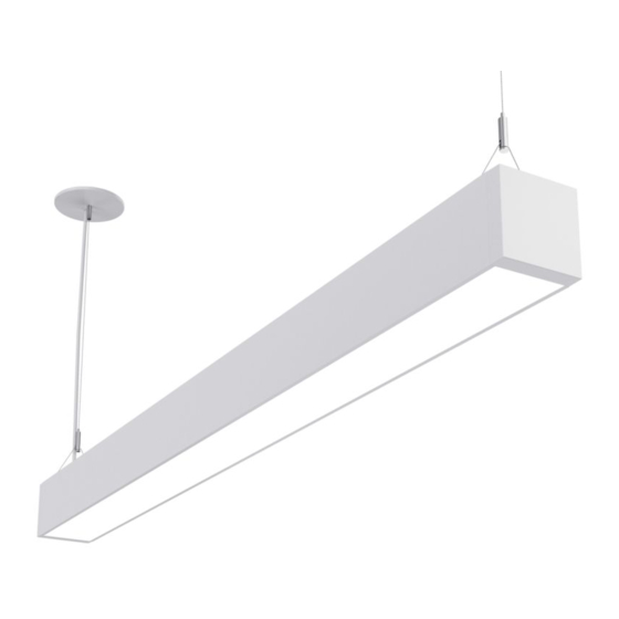
Related Manuals for Cooper Lighting Corelite Continua SQ4


Summary of Contents for Cooper Lighting Corelite Continua SQ4
- Page 1 Risk of Burn. Disconnect power and allow fixture to cool construction and operation of the product and the hazards involved. Cooper Lighting Solutions assumes before handling fixture. no responsibility for claims brought about by improper or careless installation or handling of this product.
- Page 2 MOUNTING POINTS EQUAL FIXTURE LENGTHS 4’, 6‘,8’ or 12’ FIXTURE LENGTHS 4’, 6‘, 8’ or 12’ POWER FEED FIRST SECTION FIRST SECTION ***CONSECUTIVE SECTIONS ***CONSECUTIVE SECTIONS For installation at ceiling, see separate ceiling interface instructions. Cooper Lighting Solutions Installation instructions...
- Page 3 Slide cross cable into fixture end. Mounting points can be adjusted inward later as needed. Bend tabs upward after inserting cross cable into fixture in order to retain cross cable during installation. Power Drop Insert Supplied Bushing Attach Strain Relief as shown Cooper Lighting Solutions Installation instructions...
- Page 4 One person hold roll lens at one end of fixture (as shown) while another person pulls lens through. IMPORTANT: Ends of lens should overhang fixture by ¼” at each end. Trim lens where necessary. DO NOT UNDER-CUT. 0.25” Cooper Lighting Solutions Installation instructions...
- Page 5 If additional cleaning is required it while holding the Sensor body in place is recommended to use Clorox® wipes to remove remaining contaminants by gently rubbing the affected area and allowing to air dry. Cooper Lighting Solutions Installation instructions...
- Page 6 Warranties and Limitation of Liability Please refer to www.cooperlighting.com/WarrantyTerms for our terms and conditions. Garanties et limitation de responsabilité Veuillez consulter le site www.cooperlighting.com/WarrantyTerms pour obtenir les conditions générales. Garantías y Limitación de Responsabilidad Visite www.cooperlighting.com/WarrantyTerms para conocer nuestros términos y condiciones. FCC Statement •...