
Related Manuals for Custom Audio Electronics KPM 216 H


Summary of Contents for Custom Audio Electronics KPM 216 H
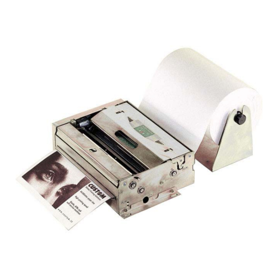
- Page 1 Thermal printer for information kiosks and ATMs KPM 216 H 210/216mm (8.5”) User Manual www.custom.it KPM216H...
- Page 2 All rights reserved. Total or partial reproduction of this manual in whatever form, whether by printed or electronic means, is forbidden. While guaranteeing that the information contained in it has been carefully checked, CUSTOM ENGINEERING SPA and other entities utilized in the realization of this manual bear no responsibility for how the manual is used.
- Page 3 PRINTER COMPONENTS A. KPM216H – Front external view 1- Printing head set 2- Opening lever of head set 3- Roller cover 4- Paper exit 5- Lock/Unlock button of motorization cover 6- Motorization cover Available in two versions: horizontal or vertical (option 0090) paper delivery. KPM216H...
- Page 4 B. KPM216H – Rear external view 1- Paper load 2- Paper feed guides (adjustable) 3- Status led 4- Feed key 5- Print key 6- Reset key 7- External near paper end sensor connector 8- Motorization cover 9- Printing head set 10- Opening lever of head set 11- Tilting paper holder 12- Paper ejector rollers unit...
- Page 5 C. KPM216H – Under view KPM216H-U model 1- Serial connector 2- USB connector 3- Power supply connector 4- Power supply fuse KPM216H-P model 5- Serial connector 6- Centronics connector 7- Power supply fuse 8- Power supply connector KPM216H-U KPM216H-P model model KPM216H...
- Page 6 Blank page KPM216H...
-
Page 7: Table Of Contents
TABLE OF CONTENTS INTRODUCTION MANUAL CONTENTS ......................1 EXPLANATORY NOTES USED IN THIS MANUAL .............. 1 GENERAL SAFETY INFORMATION ..................1 UNPACKING THE PRINTER ....................2 PRINTER FEATURES ......................3 PRINTER DESCRIPTION ..................... 4 1. INSTALLATION AND USE 1.1 CONNECTIONS ......................1-1 1.1.1 Power Supply ....................... - Page 8 TABLE OF CONTENTS Blank page KPM216H...
-
Page 9: Introduction
INTRODUCTION MANUAL CONTENTS In addition to the Introduction which includes a description of the explanatory notes used in the manual, general safety information, how to unpack the printer and a brief description of the printer including its basic features, this manual is organized as follows: Chapter 1: Contains the information required for correct printer installation and its proper Chapter 2:... -
Page 10: Unpacking The Printer
INTRODUCTION • Do not introduce foreign objects of any kind into the printer as this could cause a short circuit or damage parts that could jeopardize printer functioning. • Do not spill liquids onto the printer. • Be careful when working on the printer because the head area is ESD (electrostatic discharge) sensitive. -
Page 11: Printer Features
INTRODUCTION (Fig.1) PRINTER FEATURES It’s an A4/US letter format thermal printer designed for Internet, information and reservation kiosks and automatic teller (ATM) machines. It is available in two models: 204 dpi (8 dots/mm) thermal printing mechanism version and 300 dpi (11.8 dots/mm) thermal printing mechanism version. Both versions utilize 210/216 mm-wide paper rolls. -
Page 12: Printer Description
INTRODUCTION • Easy paper changing (automatic paper loading). • Paper width: 210/216 mm (8.5”). • Bar code UPC-A. UPC-E, EAN13, EAN8, CODE39, ITF, CODABAR, CODE93, CODE128 and CODE32. • 3 standard and international character set fonts. • Definition of function macros for automatic operation re-call. •... - Page 13 INTRODUCTION (Tab.1) t n i i r c y t i t n i i r c o l l a t l i r c t t u (Fig.2) KPM216H...
- Page 14 INTRODUCTION Blank page KPM216H...
-
Page 15: Installation And Use
1. INSTALLATION AND USE 1.1 CONNECTIONS (Fig.1.1) 1.1.1 Power Supply The printer is equipped with an external power supply outlet (see Fig. 1.1). The connector pin configuration is as follows: Model no. type : Header : Molex 39-30-0060 (Vertical) Housing: Molex 39-01-2065 (Tab.1.1) WARNING: Respect power supply polarity. -
Page 16: Additional Brackets Assembling
1. INSTALLATION AND USE This picture shows the power supply cable included in the printer packaging : BLACK (Fig.1.2) BLACK OPPOSITE VIEW SIDE 6 PIN (3X2) CABLE INSERTION FEMALE CONNECTOR The connector pin configuration of this cable is as follows: Note : The red cable is for +24 Vdc. -
Page 17: Self-Test
1. INSTALLATION AND USE Right side (dx) (Fig.1.3) Left side (sx) (Fig.1.4) 1.3 SELF-TEST Printer operating status is indicated in the configuration print-out in which, next to the name of the components displayed (see figures 1.5 and 1.6), the following information is given: •... -
Page 18: Configuration
1. INSTALLATION AND USE KPM216H-U MODEL KPM216H-P MODEL * PRINTER SETUP * * PRINTER SETUP * INTERFACE ......... RS232, INTERFACE ......RS232/ CENTRONICS PROGRAM MEMORY TEST..OK PROGRAM MEMORY TEST..OK DYNAMIC RAM TEST ....OK DYNAMIC RAM TEST ....OK EEPROM TEST ......EEPROM TEST ...... - Page 19 1. INSTALLATION AND USE • USB Address Number : 0 , 1, 2, 3, 4, 5, 6, 7, 8, 9. • USB Status Monitor : Disabled or Enabled. • Autofeed: CR disabled or CR enabled. • Print mode: Normal or Reverse. •...
-
Page 20: Hexadecimal Dump
1. INSTALLATION AND USE The settings made are stored in EEPROM (nonvolatile memory). During power-up, if the FORM FEED key is held down, the printer enters the autotest routine and prints out the setup report. The printer will remain in standby in Hexadecimal dump mode (see section 1.5) until another key is pressed or characters are received through the printer communication port. -
Page 21: Paper Load Specifications
1. INSTALLATION AND USE a: Printing head (Fig.1.8) b: Printing roll Dispenser rolls Horizontal paper exit Vertical paper exit (Fig.1.9) WARNING Before inserting the paper, make sure it is cut cleanly. WARNING Make sure the paper and printer are aligned (fig.1.10 and fig. 1.11) 1.6.2 Paper load specifications To correctly load the paper, follow the alignment instructions shown in figs. - Page 22 1. INSTALLATION AND USE Paper direction axis 1° 1° (Fig.1.11) WARNING The roll must be perfectly aligned with the printer (fig. 1.11). The maximum play allowed is ± 1%. KPM216H...
-
Page 24: Paper Jam
1. INSTALLATION AND USE 1.6.4 Paper jam In the event of a jam along the paper path, proceed as follows: turn the printer off and on, before removing the paper, in order to cut the paper and attempt to have it ejected. If this does not solve the problem, proceed as follows: Paper jammed on ejector (see fig. - Page 25 1. INSTALLATION AND USE (Fig.1.16) 2) Open the lateral cover (1) rotating the lock/unlock button (2) with the screwdriver or coin (see fig.1.17). N.B.: To close lateral cover, once reassembled it , push the the lock/unlock button. (Fig.1.17) KPM216H...
- Page 26 1. INSTALLATION AND USE Extract the cover unit pulling from the bottom to the outside and then lifting up to release the two slots (see fig.1.18). (Fig.1.18) 4) Pulling up the cutter as shown in the fig. 1.19; remove any pieces of paper. (Fig.1.19) ATTENTION Remove the cover before...
-
Page 27: Cleaning The Print Head
1. INSTALLATION AND USE 1.6.5 Cleaning the printing head WARNING • Do not touch the head heating line with bare hands or metal objects. • Do not perform any operation inside the printer immediately after printing because the head and motor tend to become very hot. •... - Page 28 1. INSTALLATION AND USE 2) Clean the printing head heating line (1) using a non-abrasive cloth moistened with denatured alcohol (see fig. 1.21) (Fig.1.21) Clean the heating line (black line indicated by the arrow) 3) Lower the cover (1) to close and pressing (2) in the exact point indicated from the label located on the cover as shown in the fig.
-
Page 29: Cleaning The Ejector Rollers
1. INSTALLATION AND USE 1.6.6 Cleaning the ejector rollers WARNING • The printer must be turned off during cleaning operations. • Caution during cleaning operations to tilting paper holder(3). Turn off the printer and proceed as follows: 1) Lift up the roller cover (1) as shown in fig. 1.24. 2) Clean the rollers (2) using a medium-stiff brush to avoid them being scratched. -
Page 30: Ticket Characteristics
1. INSTALLATION AND USE 1.7 TICKET CHARACTERISTICS 1.7.1 Ticket characteristics It’s possible to use paper with alignment mark. The figure 1.25 shows paper with alignment mark fac-simile; the notch distance in mm from the beginning of the document must be setting during the printer setup. -
Page 31: Interfaces
2. INTERFACES (Fig.2.1) 9 8 7 6 2.1 RS232 SERIAL The printer has an RS232 interface with 9-pin female connector. Refer to the table below for the connector pin signals: (Tab.2.1) t n i i t c t n i i t c i t c KPM216H... - Page 32 2. INTERFACES The diagrams below illustrate a sample connection between the printer and PC using a 25- or 9-pin female connector. (Fig.2.2) SIGNAL GND KPM216H (Fig.2.3) SIGNAL GND KPM216H KPM216H...
-
Page 33: Usb Serial Interface
2. INTERFACES 2.2 USB SERIAL INTERFACE Printers with USB serial interface conform to USB 1.1 standards and have the following specifications: • Communication speed 12 Mbit/sec • “Receptacle series B”-type connector. Refer to the table below for the connector pin signals and connection to a device: (Tab.2.2) Fig. - Page 34 2. INTERFACES For the parallel connector, the connection between printer and Personal Computer, must be made with a 25- pin- to- pin connector. (Fig.2.5) SERIAL PARALLEL 9 8 7 6 KPM216H...
-
Page 35: Esc/Pos Emulation
3. PRINTER FUNCTIONS 3. PRINTER FUNCTIONS 3.1 PRINT DIRECTION The printer has two printing directions which can be selected by means of the control characters:normal and reverse. (Fig.3.1) Normal mode 3.2 COMMAND DESCRIPTIONS The table 3.1 shows the commmands list, ordered by their hexadecimal value. LEGEND : Symbol Function... - Page 36 3. PRINTER FUNCTIONS i t - l n i l t n i t i s c / t & i t a c i t t n i t i s n i l n i l n i l n i l i n i s t i...
- Page 37 3. PRINTER FUNCTIONS 3. PRINTER FUNCTIONS t n i t n i t n i y t i c i t s t i c i t a l i r i v t n i t n i g i l r i f t n i n i l...
- Page 38 3. PRINTER FUNCTIONS [Reference] [Example] [Name] Horizontal tab [Format] ASCII Decimal [Description] Moves the print position to the next horizontal tab position. [Notes] • Ignored unless the next horizontal tab position has been set. • If the command is received when the printing position is at the right mar- gin, the printer executes print buffer full printing and horizontal tab process- ing from the beginning of the next line.
- Page 39 3. PRINTER FUNCTIONS 3. PRINTER FUNCTIONS [Name] Print and carriage return [Format] ASCII Decimal [Description] When autofeed is “CR enabled”, this command functions in the same way as LF, otherwise it is disregarded. [Notes] • Sets the print position to the beginning of the line. [Default] See “Autofeed in setup”...
- Page 40 3. PRINTER FUNCTIONS n=1: Printer status n i l - f f n i l n=2: Off-line status t ' n . t n t n i n=3: Error status t t u t t u KPM216H...
- Page 41 3. PRINTER FUNCTIONS 3. PRINTER FUNCTIONS n=4: Paper roll sensor status 2 3 , . t n . t n n=17: Print status . f f . t n . t n n=20: FULL status (6 bytes) 1° Byte = 0x10 (DLE) 2°...
- Page 42 3. PRINTER FUNCTIONS 4° byte = USER STATUS n i l n i l . f f 5° byte = Recoverable error Status O f f a t l a t l . h t KPM216H...
- Page 43 3. PRINTER FUNCTIONS 3. PRINTER FUNCTIONS 6° byte = Unrecoverable error Status t t u t t u [Name] Cancel current line transmitted [Format] ASCII Decimal [Description] Deletes current line transmitted. [Notes] • Sets the print position to the beginning of the line. •...
- Page 44 3. PRINTER FUNCTIONS spacing. • The GS P command can change the horizontal (and vertical) motion unit. However, the value cannot be less than the minimum horizontal movement amount. • In standard mode, the horizontal motion unit is used. • The maximum right side spacing is: 255/204 inches for the 204 dpi model 255/300 inches for the 300 dpi model.
- Page 45 3. PRINTER FUNCTIONS 3. PRINTER FUNCTIONS the last-received setting command is the effective one. • ESC - can also be used to turn the underlining mode on/off. However, the last-received setting command is the effective one. • ESC 4 can also be used to turn the italic mode on/off. However, the last- received setting command is the effective one.
- Page 46 3. PRINTER FUNCTIONS When the LSB of n is 1, the user-defined character set is selected. [Notes] • Only the LSB of n is applicable. • When the user-defined character set is canceled, the internal character set is automatically selected. [Default] [Reference] ESC &, ESC ?
- Page 47 3. PRINTER FUNCTIONS 3. PRINTER FUNCTIONS [Example] [Name] Set relative vertical print position [Format] ASCII Decimal 0 ≤ nL ≤ 255 [Range] 0 ≤ nH ≤ 255 [Description] Sets the print vertical position based on the current position by using the horizontal or vertical motion unit.
- Page 48 3. PRINTER FUNCTIONS [Name] Turn underline mode on/off [Format] ASCII Decimal 0 ≤ n ≤ 2, 48 ≤ n ≤ 50 [Range] [Description] Turns underline mode on or off, based on the following values of n: n = 0, 48Turns off underline mode n = 1, 49Turns on underline mode (1-dot thick) n = 2, 50Turns on underline mode (2-dot thick) [Notes]...
- Page 49 3. PRINTER FUNCTIONS 3. PRINTER FUNCTIONS [Reference] ESC 0, ESC 3 [Example] [Name] Set line spacing [Format] ASCII Decimal 0 ≤ n ≤ 255 [Range] Sets line spacing to [ n × (vertical or horizontal motion unit)] inches. [Description] [Notes] •...
- Page 50 3. PRINTER FUNCTIONS [Name] Initialize printer [Format] ASCII Decimal [Description] Clears the data in the print buffer and resets the printer mode to that in effect when power was turned on. [Notes] • The data in the receiver buffer is not cleared. •...
- Page 51 3. PRINTER FUNCTIONS 3. PRINTER FUNCTIONS [Notes] • Only the LSB of n is effective. • ESC ! also turns on and off the emphasized mode. However, the last received command is the effective one. [Default] n = 0 [Reference] ESC ! [Example] [Name]...
- Page 52 3. PRINTER FUNCTIONS Justification 0, 48 Flush left 1, 49 Centered 2, 50 Flush right [Notes] • This command is only enabled when inserted at the beginning of a line. • Lines are justified within the specified printing area. • Spaces set by HT, ESC $ and ESC \ will be justified according to the previously-entered mode.
- Page 53 3. PRINTER FUNCTIONS 3. PRINTER FUNCTIONS [Example] [Name] Set/reset red printing mode [Format] ASCII ESC r Decimal 0 ≤ n ≤ 1, 48 ≤ n ≤ 49 [Range] [Description] Sets and resets red printing mode. Function 0, 48 Reset red printing mode 1, 49 Set red printing mode [Notes]...
- Page 54 3. PRINTER FUNCTIONS [Reference] DLE EOT [Example] [Name] Set/cancel cpi mode [Format] ASCII ESC { } Decimal 193 n 0 ≤ n ≤ 1, 48 ≤ n ≤ 49 [Range] [Description] Sets cpi mode based on the following values of n: [Default] n = 0 [Reference]...
- Page 55 3. PRINTER FUNCTIONS 3. PRINTER FUNCTIONS yL + yH × 256 specifies the number of lines to print. • If (xL + (xH × 256)) > dhmax the printer does not execute the command. [Notes] • If ( xL + ( xH × 256 ) + yL +( yH × 256 ))> dhmax the printer prints only dhmax - xL + ( xH ×...
- Page 56 3. PRINTER FUNCTIONS graphic page are the commands ESC ·, ESC ¹, ESC ¦ and the status commands. • To print strings character and logo from ram proceed as follows : 1) send strings character with a LF ending command; 2) send 0x1B 0xFC 0x01 for transfer logo into ram;...
- Page 57 3. PRINTER FUNCTIONS 3. PRINTER FUNCTIONS a l f [Notes] • This command makes the flash copy of the graphic page in use. If the graphic page has been cancelled by a printing command, the stored logo will be white. [Default] [Reference] ESC ·, ESC ², ESC ³...
- Page 58 3. PRINTER FUNCTIONS [Example] [Name] Turn white/black reverse printing mode on/off [Format] ASCII Decimal 29 0 ≤ n ≤ 255 [Range] [Description] Turns white/black reverse printing mode on or off. • When the LSB of n is 0, white/black reverse printing is turned off. •...
- Page 59 3. PRINTER FUNCTIONS 3. PRINTER FUNCTIONS [Reference] GS f, GS k [Example] [Name] Transmit printer ID [Format] ASCII GS I Decimal 29 1 ≤ n ≤ 3, 49 ≤ n ≤ 51 [Range] [Description] Transmits the printer ID specified by n follows: t n i c i f t n i...
- Page 60 3. PRINTER FUNCTIONS [Name] Set left margin [Format] ASCII Decimal 0 ≤ nL, nH ≤ 255 [Range] [Description] Sets the left margin. • The left margin is set to [(nL + nH × 256) × (horizontal motion unit)] inches. Printable area Left margin Printing area width [Notes]...
- Page 61 3. PRINTER FUNCTIONS 3. PRINTER FUNCTIONS • In standard mode, the following commands use x or y, regardless of character rotation (upside-down or 90° clockwise rotation): Commands using x : GS L, GS W. Commands using y : ESC J. •...
- Page 62 3. PRINTER FUNCTIONS 0 ≤ nL, nH ≤ 255 [Range] 0 ≤ nL + nH x 256) ≤ 832 [Description] Sets the printing area width to the area specified by nL and nH. • The left margin is set to [(nL + nH × 256) × (horizontal motion unit)] inches.
- Page 63 3. PRINTER FUNCTIONS 3. PRINTER FUNCTIONS . ) t . ) t . t u . t u O f f s ' r o . f f s ' r t t i . f f t t i [Notes] m must be sent with n = 3;...
- Page 64 3. PRINTER FUNCTIONS [Notes] HRI characters are printed at the position specified by GS H. [Default] n = 0 [Reference] GS H, GS k [Example] [Name] Set bar code height [Format] ASCII Decimal 1 ≤ n ≤ 255 [Range] [Description] Sets the height of the bar code.
- Page 65 3. PRINTER FUNCTIONS 3. PRINTER FUNCTIONS 1 ≤ k ≤ 2 4 ≤ d ≤ 7 1 ≤ k ≤ 2 4 ≤ d ≤ 7 1 ≤ k ≤ 3 4 ≤ d ≤ 7 7 ≤ k ≤ 8 4 ≤...
- Page 66 3. PRINTER FUNCTIONS code data after receiving 7 (without check digit) or 8 (with check digit) bytes bar code data. • The number of data for ITF bar code must be even numbers. When an odd number of data is input, the printer ignores the last received data. [Notes per •...
- Page 67 3. PRINTER FUNCTIONS 3. PRINTER FUNCTIONS [Name] Transmit status [Format] ASCII Decimal 114 n [Range] n = 1, 49 [Description] Transmits the status specified by n as follows: Function 1, 49 Transmits paper sensor status (as for ESC v). Paper sensor status (n = 1, 49) 0 1 , [Notes] •...
- Page 68 3. PRINTER FUNCTIONS [Notes] [Default] n = 3 [Reference] GS k [Example] [Name] Set printing density [Format] ASCII Decimal 0 ≤ n ≤ 8, 48 ≤ n ≤ 56, [Range] [Description] Sets printing density. n specifies printing density as follows: t n i y t i [Notes]...
- Page 69 3. PRINTER FUNCTIONS 3. PRINTER FUNCTIONS [Name] Set horizontal and vertical motion units [Format] ASCII yH yL yH yL Decimal yH yL 0 ≤ ((xH * 256) + xL) ≤ 2040 [Range] 0 ≤ ((yH * 256) + yL) ≤ 4080 [Description] Sets the horizontal and vertical motion units to 1/((xH * 256) + xL) inch and 1/((yH * 256) + yL) inch respectively.
- Page 70 3. PRINTER FUNCTIONS [Notes] • Once enable at least one byte of the FULL STATUS, for each change of at least one of the bits which compose the required status, the status sent in automatic from the printer will be so composed as follows: 1°...
- Page 71 3. PRINTER FUNCTIONS 3. PRINTER FUNCTIONS [Name] Reading number of cuts performed from the printer [Format] ASCII Decimal [Description] Reading the number of cuts performed from the printer. The command return a string that points out how many cuts are performed by the printer, for example if there are performed 2376 cuts, it will be: ‘2376 cuts’...
- Page 72 3. PRINTER FUNCTIONS [Name] Reading number of power up [Format] ASCII Decimal [Description] Reading number of power up of the printer. [Notes] • The command return a string pointing out the number of turning on of the printer, for example if the printer is turned on 512 times, it will be: ‘512on’...
- Page 73 3. PRINTER FUNCTIONS 3. PRINTER FUNCTIONS [Description] Sets notch distance in mm from the beginning of the document (see fig. 1.4). [Notes] • This value is expressed as [(nH x 256)+nL] • The maximum value is 999 mm [Default] nH = 0x00, nL = 0x00 [Reference] [Example] [Name]...
- Page 74 3. PRINTER FUNCTIONS [Name] Ticket align at cut [Format] ASCII Decimal [Description] This command searchs a paper notch and then align the ticket at cut. [Notes] [Reference] $1D $F6 [Example] F [Name] Hardware reset [Format] ASCII $14 $1A...
-
Page 75: Technical Specifications
4. TECHNICAL SPECIFICATIONS 4.1 TECHNICAL SPECIFICATIONS (Tab.4.1) Table 4.1 gives the main technical specifications of the 204 dpi printer model. i f l s l l i t i l l o " 5 t e l ± ± ± i h t Ø... - Page 76 4. TECHNICAL SPECIFICATIONS y t i ± ) y l ° 0 ¸ ° 0 i t a y t i y t i ° ¸ ° , t r ° 0 t i x ) l l Note : Dependent of power of power supply utilized. Note : If the “Short Ticket”...
- Page 77 4. TECHNICAL SPECIFICATIONS l " ± ± ± l l o Ø , ° , ° ° 0 c i l i l a ± Note : For external rolls diameter higher to 100mm it’s recommended to use a paper pre tensioning device. Note : Dependent of power of power supply utilized.
-
Page 78: Dimensions
4. TECHNICAL SPECIFICATIONS ° 0 ¸ ° 0 i t a y t i ¸ y t i ° ° ¸ , t r ° 0 t i x ) l l Note : If the “Short Ticket” parameter is enabled (see the paragraph 1.4 Configuration), it’s possible to reach the minimum length of 110 mm. - Page 79 4. TECHNICAL SPECIFICATIONS Rear view (Fig.4.2) Top view (Fig.4.3) ÷ 212 (Paper input) Right-side view (Dx) (Fig.4.4) Paper input Vertical paper output Horizontal paper output KPM216H...
- Page 80 4. TECHNICAL SPECIFICATIONS (Fig.4.5) Left-side view (Sx) with cover open 110° Front view with cover open (Fig.4.6) 100° WARNING! MOVING PARTS KPM216H...
- Page 81 4. TECHNICAL SPECIFICATIONS Paper outfeed direction In the following figures is showed the printer paper input (1) and paper output (2); in the fig. 4.8 is illustrated the optional model with vertical paper exit. (Fig. 4.7) (Fig.4.8) KPM216H...
- Page 82 4. TECHNICAL SPECIFICATIONS Blank page KPM216H...
-
Page 83: Character Sets
5. CHARACTER SETS 5.1 CHARACTER SETS The printer has 3 fonts of varying width for the 204 dpi (11, 15 and 20 cpi) and 300 dpi (17, 23 and 30 cpi) models, which may be accessed through programming (section 1.2) or control characters (section 3.2). - Page 84 5. CHARACTER SETS Blank page KPM216H...
-
Page 85: Appendix A - Accessories And Spare Parts
APPENDIX A - ACCESSORIES AND SPARE PARTS A.1 ACCESSORIES A.1.1 Power Supply The figure below illustrates the power supply provided by Custom to be used for printer operation. (Fig.A.1) 203.0 50.4 LED 1 187.0 (Tab.A.1) − a t l − −... -
Page 86: Supplies
APPENDIX A - ACCESSORIES AND SPARE PARTS A.2 SUPPLIES (Tab.A.2) A.3 NOTES FOR TECHNICAL ASSISTANCE ATTENTION • The operations here described are exclusively aimed to the personnel handling the technical assistance of the printer. A.3.1 Replacement of roller motorization belt ATTENTION •... - Page 87 APPENDIX A - ACCESSORIES AND SPARE PARTS 2) Remove the belt, between the two pulleys, from its seating as shown in fig. A.2. (Fig.A.2) 3) Replace the belt and place it again between the two pulleys in its seating, as shown in fig. A.3.
-
Page 88: Replacing Fuse
APPENDIX A - ACCESSORIES AND SPARE PARTS A.3.2 Replacing fuse ATTENTION • The printer must be turned off during maintenance operations. Turn off the printer and proceed as follows: 1) To replace the fuse get access to the control board (4) located in the internal bottom side of the printer, and then follow maintenance operations described into paragraph 1.6.4 relevant to paper jam (lift the printing head (1), remove the lateral cover (2), lift up the cutter (3).