Table of Contents
Advertisement
Advertisement
Table of Contents

Related Manuals for Panasonic HMX700 Series


Summary of Contents for Panasonic HMX700 Series
- Page 1 TOUCH TERMINALS HMX700 Series Instruction Manual ACGM0197V1EN Version 2.04...
-
Page 2: Table Of Contents
Table of contents Introduction ...........................3 Important symbols ........................4 Special instructions for use ......................5 Standards and approvals ......................6 Product overview ..........................7 Product identification ........................8 Technical data common to all models ..................9 7.1 Hardware specifications ......................9 7.2 Environmental conditions ......................9 7.3 Electromagnetic compatibility (EMC) ..................10 7.4 Durability information ......................10 Technical data by model ...................... -
Page 3: Introduction
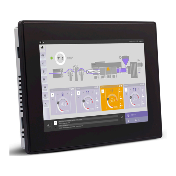
Introduction Introduction This instruction manual contains information about the installation, transportation, storage, assembly, use and maintenance of touch terminals of the HMX700 series. The following models are available: • HMX705: Touch terminal with 5” TFT color widescreen, multi-touch capacitive touch screen • HMX707: Touch terminal with 7” TFT color widescreen, multi-touch capacitive touch screen • HMX710: Touch terminal with 10.1” TFT color widescreen, multi-touch capacitive touch screen • HMX715: Touch terminal with 15.6” TFT color widescreen, multi-touch capacitive touch screen • HMX721: Touch terminal with 21.5” TFT color widescreen, multi-touch capacitive touch screen... -
Page 4: Important Symbols
Important symbols Important symbols One or more of the following symbols may be used in this documentation to indicate the type of haz- ard. DANGER Indicates a hazardous situation which, if not avoided, will result in death or serious injury. WARNING Indicates a hazardous situation which, if not avoided, could result in death or serious injury. CAUTION Indicates a hazardous situation which, if not avoided, could result in serious or moderate injury. Notice Indicates a property damage message. -
Page 5: Special Instructions For Use
Special instructions for use Special instructions for use • The product shall only be used in an area of not more than pollution degree 2, as defined in IEC/ EN 60664-1. • The product shall be installed in an enclosure that provides a degree of protection not less than IP54 in accordance with IEC/EN 60079-15. • Transient protection shall be provided that is set at a level not exceeding 140% of the peak rated voltage value at the supply terminals to the product. • Install the product according to the accompanying installation instructions. • Ground the product according to the accompanying installation instructions. • Only qualified personnel may install or repair the product. • Ensure that the ventilation holes are not covered. • Care shall be taken to avoid that layers of dust form on the touch terminals in a way that might cause the accumulation of static charges. • Keep the faceplate of the product clean. The product must be cleaned only with a soft cloth and neutral soap product. Do not use solvents. • This product should not be used for purposes and methods other than indicated in this document and in the documentation accompanying the product. -
Page 6: Standards And Approvals
Standards and approvals Standards and approvals The products have been designed for use in an industrial environment in compliance with the 2014/30/ EU EMC Directive. The products have been designed in compliance with: EN 61000-6-4 CISPR 22 Class A CISPR 16-2-3 EN 61000-6-2 EN 61000-4-2 EN 61000-4-3 EN 61000-4-4 EN 61000-4-5 EN 61000-4-6 EN 61000-4-8 EN 61000-4-11 EN 61000-4-29 EN 60945 The installation of these products into the residential, commercial and light-industrial environments is allowed only in the case that special in measures are taken in order to ensure conformity to EN 61000-6-3. The products are in compliance with the Restrictions on Certain Hazardous Substances (RoHS) Direc- tive 2011/65/EU. In compliance with the above regulations the products are CE marked. -
Page 7: Product Overview
Product overview Product overview The HMX700 series touch terminals combine state-of-the-art connectivity features and top perfor- mance with an outstanding design. The products have been designed as IoT edge devices. They combine a powerful controller with networking capability (up to 3 Ethernet networks) and outstanding communication options including client/server OPC UA. They are the ideal choice for all demanding IoT edge applications including factory, marine and building automation. The glass projected capacitive touch screen with a brilliant display up to 21.5” and a resolution of 1920x1080 guarantees great optical performance. With the support of multi-touch gesture programming the HMX700 series touch terminals can provide the most natural human interfaces. The HMX700 series touch terminals have been designed to run the HMWIN software for powerful HMI applications. • OPC UA server / client gateway • Secure connectivity with Corvina Cloud and full network separation • Powerful browser with industry standard web engines • Optional plug-in modules... -
Page 8: Product Identification
Product identification Product identification The product may be identified through a plate attached to the rear cover. You will have to know the product type you are using for correct usage of the information contained in the guide. The following information is provided by the plate: • Product model name • Product part number • Year/week of production • Version ID of the product • Serial number... -
Page 9: Technical Data Common To All Models
Technical data common to all models Technical data common to all models Hardware specifications Touch screen technology Projected capacitive Real-time clock back-up 3V, 50mAh lithium, rechargeable, not user-replaceable, model battery VL2330 Fuse Automatic Serial port RS232, RS485, RS422 software configurable Flash 4GB (HMX705, HMX707, HMX710) 8GB (HMX715, HMX721) 512MB (HMX705) 1GB (HMX707, HMX710) 2GB (HMX715, HMX721) Hardware clock Clock/calendar with back-up battery Accuracy real-time clock <100ppm (at 25°C) Environmental conditions Operating temperature -20 – +60°C (vertical installation) EN 60068-2-14... -
Page 10: Electromagnetic Compatibility (Emc)
Technical data common to all models Electromagnetic compatibility (EMC) Radiated disturbance test Class A CISPR 22 CISPR 16-2-3 Electrostatic discharge immunity 8kV (air electrostatic discharge) EN 61000-4-2 test 4kV (contact electrostatic discharge) Radiated, radio frequency, 80MHz – 1GHz, 10V/m EN 61000-4-3 electromagnetic field immunity 1.4GHz – 2GHz, 3V/m test 2GHz – 2.7GHz, 1V/m Burst immunity test ± 2KV DC power port EN 61000-4-4 ± 1KV signal line Surge immunity test ± 0.5KV DC power port (line to earth) EN 61000-4-5 ± 0.5KV DC power port (line to line) ± 1KV signal line (line to earth) Immunity to conducted 0.15 – 80MHz, 10V EN 61000-4-6 disturbances inducted by radio... -
Page 11: Technical Data By Model
Technical data by model Technical data by model HMX705, HMX707, HMX710 Model HMX705 HMX707 HMX710 Display / Backlight TFT Color / LED Colors Resolution 800 x 480 1280 x 800 Display size (inch) 5” widescreen 7” widescreen 10.1” widescreen Dimming User memory flash SD card slot 512MB Serial port RS232, RS485, RS422 software configurable Ethernet port 2x 10/100Mbit 2x 10/100Mbit 1x 10/100/1000Mbit USB port 1 host interface... -
Page 12: Hmx715, Hmx721
Technical data by model HMX715, HMX721 Model HMX715 HMX721 Display / Backlight TFT Color / LED Colors Resolution 1366 x 768 1920 x 1080 Display size (inch) 15.6” widescreen 21.5” widescreen Dimming User memory flash SD card slot Serial port RS232, RS485, RS422 software configurable Ethernet port 2x 10/100Mbit 2x 10/100Mbit with integrated switch 1x 10/100/1000Mbit 1x 10/100/1000Mbit USB port 2 host interfaces version 2.0, max. 500mA Expansion slot 2 optional plug-ins Battery rechargeable Real-time clock... -
Page 13: Unpacking And Packing Instructions
Unpacking and packing instructions Unpacking and packing instructions HMX705, HMX707, HMX710 HMX715, HMX721 To repack the product, please follow the instructions backwards. -
Page 14: Product Dimensions
Product dimensions 10. Product dimensions 10.1 HMX705 Cut out Model HMX705 147mm 107mm 136mm 96mm 56mm... -
Page 15: Hmx707 Hmx710 Hmx715 Hmx721
Product dimensions 10.2 HMX707, HMX710, HMX715, HMX721 Cut out Model HMX707 187mm 147mm 176mm 136mm 47mm HMX710 282mm 197mm 271mm 186mm 56mm HMX715 422mm 267mm 411mm 256mm 56mm HMX721 552mm 347mm 541mm 336mm 56mm... -
Page 16: Installation
Installation 11. Installation 11.1 Installation environment The product is not intended for continuous exposure to direct sunlight. There is a risk that the product might be overheating. The product is not intended for installation in contact with corrosive chemical compounds. Check the resistance of the front panel film to a specific compound before installation. Do not use tools of any kind (screwdrivers, etc.) to operate the touch screen of the product. In order to meet the front panel protection classifications, proper installation procedure must be followed: • The borders of the cutout must be flat. • Each fixing screw must be tightened until the plastic bezel corner get in contact with the panel. • The cutout for the panel must be of the dimensions indicated in this manual. IP66 is guaranteed only if: • The max. deviation from the plane surface to the cutout is ≤0.5mm. • The thickness of the case where the product is mounted is from 1.5mm to 6mm. • The max. surface roughness where the gasket is applied is ≤120μm. (1) HMX700 series touch terminal (2) Installation cutout... -
Page 17: Installation Procedure
Installation 11.2 Installation procedure For details on installation, please refer to the Installation Guide provided with the product. Place the fixing brackets contained in the fixing kit as shown in the following figure. Notice Make sure to screw each fixing screw until the bezel corner gets in contact with the product. Tightening torque: 130Ncm... -
Page 18: Connections
Connections 12. Connections 12.1 HMX705 (4) (5) (1) USB port (V2.0, max. 500mA, for maintenance only) (2) Power supply (3) Serial port (4) Ethernet port 0 (10/100Mbit) (5) Ethernet port 1 (10/100Mbit) (6) Expansion slot for plug-in module (7) SD card slot 12.2 HMX707, HMX710, HMX715, HMX721 (1) USB port (V2.0, max. 500mA, for maintenance only) (2) Ethernet port 2 (10/100Mbit) (3) Ethernet port 1 (10/100Mbit) (4) Serial port (5) Ethernet port 0 (10/100/1000Mbit) (6) Power supply (7) 2x expansion slot for plug-in module (8) SD card slot... -
Page 19: Serial Port
Connections 12.3 Serial port The serial port is used to communicate with the PLC or with another type of controller. Standards available for the signals in the PLC port connector are: RS232, RS422, RS485. Use the corresponding communication cable for the connection. The serial port is software programmable. Make sure you select the appropriate interface in the pro- gramming software. RS232 RS422, RS485 Description Description CHB- Serial port CHA- CHB+ CHA+ +5V output +5V output SHIELD SHIELD For RS485, pins 1-2 and 3-4 must be connected externally. 12.4 Ethernet port The Ethernet port has two LED status indicators. They work as shown in the following figure. Yellow LED Green LED Off: Valid link has not been detected On: No activity On: Valid link has been detected Blinking: Activity... -
Page 20: Optional Plug-Ins
Connections 12.5 Optional plug-ins There are two communication cassettes available for the HMX700 series. Depending on the touch terminal type, there are one or two expansion slots. Slot #2 and slot #4 are available only if the plug-in module is equipped with the bus extension connec- tor. Module Application Max. No. of plug-ins Bus extension connector PLCM03 Serial RS232 PLCM04 Serial RS485 If you are planning to use PLCM03 and PLCM04 (additional serial ports), the COM port numbers will be assigned as follows: • A module plugged in slot #1 or slot #2 will be COM2, • A module plugged in slot #3 or slot #4 will be COM3. -
Page 21: Power Supply, Grounding, And Shielding
Connections 12.6 Power supply, grounding, and shielding The power supply terminal block is shown in the following figure. +24V Common M 3 conductors, minimum 1,5mmq wire size, minimum temperature conductor rating 105°C NOTE Make sure that the power supply has sufficient power capacity for the operation of the product. The product must always be grounded to earth using a wire with a minimum size of 1.5mmq. Ground- ing helps limit the effects of noise due to electromagnetic interference on the control system. Earth connection will have to be done using either the screw or the faston terminal located near the power supply terminal block. A label identifies the ground connection. Also ground the terminal 3 on the power supply terminal block. The power supply circuit may be floating or grounded. In the latter case, the power source common is connected as indicated with a dashed line in the following figure. When using the floating power scheme, note that internally the power common is connected to the ground with a 1MΩ resistor in parallel with a 4,7nF capacitor. The power supply must have double or reinforced insulation. The suggested wiring for the power sup- ply is shown in the following figure. Panel All the electronic devices in the control system must be properly grounded. Grounding must be per- formed according to applicable regulations. -
Page 22: Battery
Battery 13. Battery The touch terminals are equipped with rechargeable lithium batteries that are not user-replaceable. The battery is needed to keep the real-time clock running (date and time). When the touch terminal is installed for the first time, the battery must be charged for 48 hours. When the battery is fully charged, data backup at 25°C is guaranteed for 3 months. Battery HMX705 HMX707, HMX710, HMX715, HMX721... -
Page 23: Getting Started
Getting started 14. Getting started The HMX700 series touch terminals must be programmed with the programming software HMWIN Studio (starting from v2.6), a Windows application. There are two options to transfer a HMWIN application project to a touch terminal: Ethernet Connect the touch terminal via the Ethernet interface to a personal computer running the HMWIN Studio software. Select “Run/Download to target” in HMWIN Studio. Make sure that the firewall policy is configured in a way that allows HMWIN Studio to access the network. Create an update package using the HMWIN Studio software and copy it to an USB flash drive. -
Page 24: System Settings Tool
System settings tool 15. System settings tool 15.1 Introduction The HMX700 series touch terminals have a system settings interface to allow the configuration of system options. The user interface of “System Settings” is based on HTML pages accessible locally on the touch terminal or remote using a web browser, e.g. Chrome v44 or higher on port 443. To connect, enter the address https://IP/machine_config. “IP” represents the address of the touch terminal. The default username is “admin”, and the default password is “admin”. Use the navigation menu on the left side of the screen to browse through the available options. On the left side, the selected menu item is highlighted. The right side shows related information and settings. Depending on the size of the touch terminal, menu and content of the selected menu item may not be displayed next to each other on the screen. The system settings interface has two operating modes: User mode HMWIN runtime is running or the status of the touch terminal is set to “factory default”. System mode HMWIN runtime is not running or there is a software failure. The system mode includes all options available in user mode. In addition, the system mode offers commands dedicated to system upgrade and recovery which are not available in user mode. 15.2 Activation of system settings in user mode Factory default Touch the “System Setting” button on the touch terminal. status HMWIN runtime To activate the system settings in user mode, touch and hold any unused area running... -
Page 25: Activation Of System Settings In System Mode
System settings tool 15.3 Activation of system settings in system mode Normal If HMWIN runtime is not running: operation Touch the “System Setting” button on the touch terminal to open the system set- tings in user mode. Select “Restart” > “Config OS” to reboot in system mode. If HMWIN runtime is running: To activate the system settings in user mode, touch and hold any unused area of the touch screen for a few seconds to access the context menu. The default holding time is 2 seconds. Select “Restart” > “Config OS” to reboot in system mode. Recovery If the touch terminal is not responsive, tap on the surface of the touch screen operation during the power-up phase. The tapping frequency must be high. Start tapping the touch screen as soon as power has been supplied to the product. The message “TAP-TAP DETECTED” appears when the operating sequence has been recognized. Release the touch screen to boot in user mode without running HMWIN runtime or touch and hold the touch screen for a few seconds. Then select “Restart” > “Config OS” to boot in system mode. 15.4 Options available in system settings The following important basic setting options of the touch terminal are available: Language Configure the language used for the system setting menu only. System Shows information about platform, status and timers (e.g. system on time, backlight on time). Logs Enable persistent log for BSP and allows to export it. -
Page 26: Disposal
Disposal 16. Disposal Used electrical and electronic products must not be placed in general household waste. For proper treatment, recovery and recycling of old products, take them to applicable collection points in accordance with your national legislation. By disposing of them correctly, you will help to save valuable resources and prevent any potential negative effects on human health and the environment. For more information about collection and recycling, please contact your local municipality. Dispose of batteries according to local regulations. -
Page 27: Record Of Changes
Record of changes 17. Record of changes Manual No. Date Description of changes ACGM0197V1EN February 2019 First edition based on the eX700 Series Operating Instructions version 2.04 Distributed by Panasonic Electric Works Europe AG www.panasonic-electric-works.com Subject to change without notice. The information contained in this document is provided for informational purposes only. While efforts were made to verify the accuracy of the information contained in this documentation, it is provided “as is” without warranty of any kind. Third-party brands and names are the property of their respective owners. - Page 28 Filial Nordic, Knarrarnäsgatan 15, 164 40 Kista, Sweden, Tel. +46 859476680, Fax +46 859476690, www.panasonic-electric-works.se Panasonic Eco Solutions Nordic AB Jungmansgatan 12, 21119 Malmö, Tel. +46 40 697 7000, Fax +46 40 697 7099, www.panasonic-fi re-security.com Poland Panasonic Electric Works Polska sp. z o.o ul.