Table of Contents
Advertisement
User's Manual
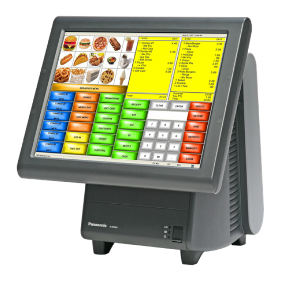
POS Workstation
JS-950
Model No.
Series
Contents
For USA / For CANADA
English
Read Me First .................... 2
3.Appendix
Before operating this product,please read the instructions carefully,
and save this manual for future use.
Advertisement
Table of Contents

Related Manuals for Panasonic JS-950 Series


Summary of Contents for Panasonic JS-950 Series
- Page 1 User’s Manual POS Workstation JS-950 Model No. Series Contents For USA / For CANADA English Read Me First …..….……..2 1.Getting Started 2.Operation 3.Appendix Before operating this product,please read the instructions carefully, and save this manual for future use.
- Page 2 ■ For USA Federal Communications Commission Radio Frequency Interference Statement This equipment has been tested and found to comply with the limits for a Class A digital device, pursuant to Part 15 of the FCC Rules. These limits are designed to provide reasonable protection against harmful interference when the equipment is operated in a commercial environment.
- Page 3 English Read Me First Introduction Thank you for purchasing the JS-950 series Panasonic POS Workstation. This manual describes the instructions for the POS Workstation. Please read this manual carefully before using this product. List of JS-950 series Product Name Model Number.
-
Page 4: Getting Started
1. Getting Started ■ Precautions [POS Workstation: JS-950 series] IMPORTANT Install a socket outlet adjacent to the equipment so that it will be easily accessible. CAUTION RISK OF EXPLOSION IF BATTERY IS REPLACED BY AN INCORRECT TYPE. DISPOSE OF USED BATTERIES ACCORDING TO THE INSTRUCTIONS. - Page 5 ■ Name of each part & function 1. Operator’s Display 2. Front SW cover 3. POP Holder 4. Rear Display 5. USB connector 6. Power SW Attention: Do not push Power SW by mistake when you insert the USB connector.
- Page 6 2. Operation ■ AC Cord Kit Installation 1. How to install the AC Cord (1) Carefully lay the Main Body Unit on a clear, flat surface as shown in figure (1). (2) Unpack the AC Cord, and then connect it to AC Inlet as shown in figure (2). (3) Fit the Cord Clamp to AC Cord, and fix it by attached screw as shown in figure (3)-1, 2 and (4) Carefully replace the Main Body Unit in upright position as shown in figure (4).
- Page 7 ■ Display Unit Installation Be sure to disconnect the power cable of the main block (POS Workstation) and confirm the power is “OFF” before the operation below. 1. How to install the display unit (1) Open the screw cover of the main unit (POS Workstation). (2) Hold the display unit with both hands and insert the connector section of the display unit into the connector inlet guide of the main unit slowly to connect the connector.
- Page 8 ■ Storage Unit Installation Be sure to disconnect the power cable of the main block (POS Workstation) and confirm the power is “OFF” before the operation below. 1. How to mount the storage unit (1) Disconnect the 2 latches on the upper portion of the filter cover of the main unit by both hands, pull the cover toward you while pressing the cover downward at the same time, and remove the filter cover.
- Page 9 ■ Rear Display Unit Installation Be sure to disconnect the power cable of the main block (POS Workstation) and confirm the power is “OFF” before the operation below. 1. How to mount the rear display unit (1) Loosen the thumbscrew on the lower portion of the rear cover at the rear display side of the main unit by hand, and remove the rear cover.
- Page 10 2. How to replace the rear display (1) Loosen the thumbscrew on the lower portion of the rear cover of the main unit by hand, and remove the rear cover. * The thumbscrew shall be loosened until the screw rotates without resistance. (2) Disconnect the connector of the rear display from the connector of the main unit.
- Page 11 ■ 2nd display unit Installation Be sure to disconnect the power cable of the main block (POS Workstation) and confirm the power is “OFF” before the operation below. 1. How to mount the 2nd Display Unit (1) Loosen the thumbscrew on the lower portion of the rear cover at the rear display side of the main block by hand, and remove the rear cover.
- Page 12 2. How to replace the 2nd Display Unit (1) In case of 950SD010, disconnect VGA cable and speaker cable from I/O panel. (2) Loosen the thumbscrew on the lower portion of the rear cover of the main block by hand, and remove the rear cover.
- Page 13 ■ ID module Unit installation Be sure to disconnect the power cable of the main block (POS Workstation) and confirm the power is “OFF” before the operation below. 1. Contents Cable cover Peripheral screw (Use only ID module 1pcs Screw 2pcs 2pcs Long type 1pcs Dallas KEY reader)
- Page 14 Tighten the screw to clamp the cable and wiring the cable as shown in the fig. (10)-4. (11) Slide USB cable cover as shown in the fig. (11)-1. In case of Dallas KEY reader, slide the USB cable cover with care to avoid the cable from the rib of the USB cable cover as shown in the fig.
- Page 15 (11)-2 (11)-1 (12) 3. How to replace the ID module unit (1) Remove Display Unit according to Display Unit Installation. (2) Prepare an ID module unit to be used. * The ID module unit is supplied with 2 pieces of peripheral screws, 2 pieces of screws, 1 piece of long cable cover, and 1 piece of short cable cover as accessories.
-
Page 16: Specifications
3. Appendix ■ Specifications [Common Specifications] Environmental condition Item Specification Operating Temperature +5°C – +40°C Operating Humidity 15% RH – 85% RH (no dew) Strage Temperature -30°C – +60°C Strage Humidity 10%RH – 90%RH [POS Workstation: JS-950WS-・・・ ] Item Specification Power Supply input AC100V-240V, 50/60 Hz, 6.0A Size... - Page 17 IO Connector layout (1) Bottom IO Connector layout USB4(+24V) COM 3 LINE-OUT Printer (Powered) USB3(+12V) ○○○○○ ○○○○○○○○○○○○○ ○○○○ ○○○○○○○○○○○○ ○○○○○ ○○○○○ ○○○○○ ○○○○○ ○○○○○ ○○○○ ○○○○○ ○○○○ ○○○○ C/D2 USB1 USB2 COM 1 COM 2 C/D1 COM 4 (Powered) (2) Rear Display Connector Layout Top of main block VFD 2lines (COM6) 2nd Display T/P &...
- Page 18 Outside drawing Main Body 12” Touch Screen 15” Touch Screen...
- Page 19 [Touch Display Unit: JS-950D・・・・・ ] Item Specification Size 12.1”: Approx. W320mm x D153mm x H256mm 15”: Approx. W364mm x D153mm x H300mm Mass 12.1”: Approx. 3.4 kg 15”: Approx. 4.4 kg Outside drawing (1) 12.1” resistive TP Display, 12.1” capacitive TP Display (2) 15”...
- Page 20 [Storage module Unit: JS-950H・・・・・ ] Item Specification Size Approx. W171mm x D126.5mm x H34mm Mass Approx. 0.8Kg (3.5”), 0.5Kg(2x CF) Outside drawing 3.5HDD module, Dual CF module...
- Page 21 [Rear Display Unit: JS-950RD-・・・ ] Item Specification Size Approx. W216.5mm x D29mm x H90mm Mass Approx. 0.4Kg (2 Lines), 0.5Kg (4Lines) Outside drawing Rear Display Module 2line, Rear Display Module 4line Rear Display module 2line Rear Display module 4line...
- Page 22 [2nd Display Unit: JS-950SD-・・・ ] Item Specification Note: It is not possible to use it together with the Rear Display Unit. Size Approx. W250mm x D72mm x H335mm Mass Approx. 1.4kg Outside drawing...
- Page 23 [MSR Unit: JS-950MG-010 ] Item Specification 2 pieces of peripheral screws accessories 2 pieces of screws 1 piece of long cable cover 1 piece of short cable cover MSR, Dallas Key and Fingerprint can not be used at the same Note: time.
- Page 24 [Dallas Key Reader Unit: JS-950DP-010 ] Item Specification 2 pieces of peripheral screws accessories 2 pieces of screws 1 piece of long cable cover 1 piece of short cable cover - Work in virtual COM I/F Note: - MSR, Dallas Key and Fingerprint can not be used at the same time.
- Page 25 [Fingerprint Sensor Unit: JS-950FS-010 ] Item Specification 2 pieces of peripheral screws accessories 2 pieces of screws 1 piece of long cable cover 1 piece of short cable cover MSR, Dallas Key and Fingerprint can not be used at the same Note: time.
- Page 26 ■ Cleaning Cleaning of outer case Light soil - Wipe case lightly with a dry, soft cloth. Heavy soil - Wipe case lightly with soft cloth pre-moistened with very diluted, mild detergent. Lightly wipe case dry with a dry, soft cloth. Cleaning of Display Wipe display gently with a dry, soft cloth to remove light dirt and dust.
- Page 27 ■ Operation Attention for capacitive touch screen (1) Do not touch it by finger nail, because capacitive touch screen can not recognize it. Touch it by finger tip. (2) Do not touch it during startup. It initializes touch screen during startup. If it is touched during startup, touch screen is not initialized correctly.
- Page 28 Intel and Celeron D are trademarks or registered trademarks of Intel Corporation in the United State of America and other countries. is a registered of trademark of Panasonic Corporation. Panasonic System Networks Company of America, Unit of Panasonic Corporation of North America Three Panasonic Way,Secaucus,New Jersey 07094 U.S.A.