Advertisement
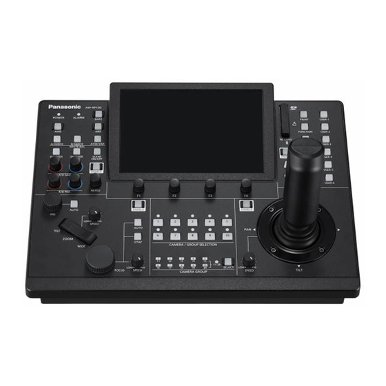
Operating guide for AW-RP150 Ver2
This document is described functions of AW-RP150 SYSTEM VERSION Ver 2.00-00-0.09. Please
see also the operating instructions of ROPs.
No.3 :A ROP setting menu is added so that the selected camera at the AW-RP150
can be activated on the connected ROP.
-
AK-HRP1000/AK-HRP1005 ver.4.80-00-0.03 or higher
-
To use the ROP linkage function, PORT number of RP150 has to be same as one of ROP.
<Setting ROP>
【MENU】>AW CONTROLLER LINK
Set up the PORT No. for RP150 to "RECEIVE PORT" and execute "INFO UPLOAD".
Set "AW CONT LINK" to ON.
<Setting RP150>
【MENU】 SYSTEM > ROP LINK
Set up "ROP IP" and "PORT" for ROP. And execute "UPLOAD".
Assign "CAMSEL" for RP150 and "ROP CAM" for ROP.
Target CAM No. can be set at "ROP CAM" against CAMSEL in RP150.
Initial setting : CAM1 –CAM99 is 1 – 99
In case of no assigned CAMERA, please set it "NON".
When "AW LINK" is turned on, RP150 starts to communicate to ROP.
CAM100 - CAM200 is NON
Advertisement

Related Manuals for Panasonic AW-RP150


Summary of Contents for Panasonic AW-RP150
- Page 1 This document is described functions of AW-RP150 SYSTEM VERSION Ver 2.00-00-0.09. Please see also the operating instructions of ROPs. No.3 :A ROP setting menu is added so that the selected camera at the AW-RP150 can be activated on the connected ROP.
- Page 2 No.4 :Linkage with AV-HS6000. Switching function is supported. 【MENU】>SYSTEM>SW LINK SETTING LINK:OFF/ON SW IP, PORT:IP Address and Port number at target BUSCONT:OFF/ON BUS:AUX1~16, ME1PVW, ME1KEY1-S/F, ME1KEY2-S/F, ME1KEY3-S/F, ME1KEY4-S/F, ME2PVW, ME2KEY1-S/F ME2KEY2-S/F, ME2KEY3-S/F, ME2KEY4-S/F, DSK1-S/K DSK2-S/K, DSK3-S/K, DSK4-S/K FOCUS ASSIST(FASIST) ON:Switch to assigned Remote Camera OFF(MV1):AUX Bus output from HS6000 switch to MV1 OFF(MV2):AUX Bus output from HS6000 switch to MV2 OFF(MV3):AUX Bus output from HS6000 switch to MV3...
- Page 3 【MENU】>SYSTEM>SW LINK ASSIGN SW INPUT:1 – 34 CAM No.:NO ASSIGN, 1 - 200 CAM No. can be assigned against SW INPUT 1- 34. No.5 : “All Delete” function of TMEM (Tracing Memory) is added. Delete function all TMEM data on the target camera. 【MENU】...
- Page 4 No7 : “ND Filter” is added to the assign items of 1-4 Knob. When you rotate dial, ND is selectable. 【MENU】 MAINTENANCE > RP SETTING > A.KNOB1~4 → 「ND」 No.8 : “ I.Zoom” status is added in Camera Info. The I.Zoom function is assignable to User Button.
- Page 5 No.10 : “IRIS LIMIT” function is added. (Only Close direction) When Iris position is decided, turn Iris Limit on, it activates 【MENU】 FUNCTION > PTZ INFP1 > IRIS LIMT → [ON/OFF] No.11 : “PRESET LIST NAME” Edit function is added. 【MENU】...
- Page 6 No.14 : Operation direction of PAN/TILT lever setting is added 【MENU】 FUNCTION > PTZ INFO2 > CTRLMODE → [CAMSEL/ALL] (Default setting is CAMSEL) ALL : Set same setting on all cameras CAMSEL : Set Individual camera Each direction of “PAN/TILT/Zoom/Focus/Iris” is according to direction information on each camera. Note: Direction information on each camera can be stored/loaded into SD card.