Table of Contents
Advertisement
Advertisement
Table of Contents

Related Manuals for Horizon Fitness APC-61 II

Summary of Contents for Horizon Fitness APC-61 II
-
Page 2: Important Information
APC-61II Important Information - This manual is designed to help you to install, operate and maintain the APC-61II Hydraulic Paper Cutter. Please read and understand this manual and keep it in a safe and convenient place. - Do not operate the APC-61II until you have read and understood the instructions in this manual. - Page 3 Safety Precautions - The term WARNING indicates a potentially hazardous situation which, if not avoided, could result in death or serious injury. - The term CAUTION indicates a potentially hazardous situation which, if not avoided, may result in damage to the machine. It may also be used to warn against unsafe practices.
- Page 4 Operating Precautions WARNING This machine must be operated by just one person at a time. When this machine is not in use, remove the key. An authorized person should keep the key so that other people can not run the machine. Various safety devices are installed on this machine.
-
Page 5: Table Of Contents
Contents Important Information ..................I Safety Precautions ....................II 1. Machine Description ............ 1 Machine Description ................. 1 Control Panel Screen Descriptions ............3 1-2-1 Mode Descriptions ..................3 1-2-2 Cutting - Normal Cutting Screen ............4 1-2-3 Cutting - Key Switch Screen ..............4 1-2-4 Cutting - Program Cutting Screen ............5 1-2-5... - Page 6 4. Operating Procedures ..........31 Cutting Operation on the Cutting Line ........... 31 Cutting Operation by Entering a Value ........... 33 Creating a Cutting Program ..............35 4-3-1 Entering the Values to Create a Program ..........35 4-3-2 Cutting the Sheets to Create a Program ..........39 4-3-3 Copying a Program ................42 4-3-4...
- Page 7 7. Installation Procedures..........81 Installation ....................81 Installing the Control Panel ..............82 Connecting the Power Cable ..............83 Adjusting the Hydraulic Pump to Match the Frequency (Only for Machines Used in 400 V Area) .............. 85 8. Appendix ..............87 Intended Use ...................
-
Page 8: Machine Description
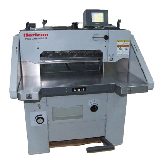
1. Machine Description This section describes the machine and the screens on the control panel. Machine Description Key Switch When this switch is ON, it turns on the hydraulic Control Panel pump. Cutting Button B The knife operates when both the A and B buttons are pressed at the same Cut Line Indicator time. - Page 9 Machine Description Locking Screw for Knife Angle Adjusting Lever Knife Angle Adjusting Lever The knife angle can be adjusted with The knife angle adjusting lever can this lever to get an even cut. be locked using this screw. Knife Paper Clamp This keeps the sheets from moving when they are cut.
-
Page 10: Control Panel Screen Descriptions
Control Panel Screen Descriptions 1-2-1 Mode Descriptions There are four modes for the control screens on the APC-61II. "Cutting" Mode Use this mode during a cutting operation. - Normal Cutting: Enter the cutting length manually for each cut. - Program Cutting: The position of the backgauge is set automatically by a saved program. -
Page 11: Cutting - Normal Cutting Screen
Control Panel Screen Descriptions 1-2-2 Cutting - Normal Cutting Screen Use this screen to enter the cutting length manually and cut the sheets to that length. Cutting Length Input When this is pressed, the numeric keypad screen appears. Enter the cutting length using the numeric keypad screen and then press The value is entered and the backgauge moves to that position. -
Page 12: Cutting - Program Cutting Screen
Control Panel Screen Descriptions 1-2-4 Cutting - Program Cutting Screen This screen is used to cut the sheets using a stored program. The backgauge is set automatically by the program, so a cutting operation can be repeated. Program Number Input When this is pressed, the Program Select Screen appears. -
Page 13: Memory- Programming Screen
Control Panel Screen Descriptions 1-2-5 Memory - Programming Screen This screen is used to create a cutting program, including settings such as cutting length and other functions, and store them as a program sequence. Program Number Input When this is pressed, the Program Select Screen appears. (See page 8.) On that screen, select the program number you want recall or save. -
Page 14: Memory- Even Divide Cutting/Total Cutting Screens
Control Panel Screen Descriptions 1-2-6 Memory - Even Divide Cutting/Total Cutting Screens Even Divide Cutting Screen Total Cutting Screen Even Divide Cutting/Total Cutting Button When this button is pressed, the "Even Divide Cutting" or the "Total Cutting" Screen is displayed. Total Length Input Enter the total length of the sheets after trimming. -
Page 15: Memory - Program Select Screen
Control Panel Screen Descriptions 1-2-7 Memory - Program Select Screen This screen is used to select a saved cutting program. Delete OK Screen Overwrite OK Screen Program Number Button (White) : This program is empty. (Gray) : This program has already saved some settings. (Black) : This program is currently selected. -
Page 16: Compression Mode Screen
Control Panel Screen Descriptions 1-2-8 Compression Mode Screen This screen is used to perform a compression operation. The paper clamp pressure can be used to press the spine of the stitched and folded booklets and reduce their bulk. Operation of the cutting buttons in the Compression Mode When the both cutting buttons are pressed, only the clamp lowers. -
Page 17: Maintenance - Knife Replacement Screen
Control Panel Screen Descriptions 1-2-9 Maintenance - Knife Replacement Screen This screen is used when replacing the knife. If this screen is displayed on the control panel, the machine changes automatically into the knife replacement mode. "Maintenance" Mode Screen "Knife Replacement" Screen Cutting Total Counter This indicates the total number of cutting cycles since the machine was new. -
Page 18: Maintenance - Lubrication Screen
Control Panel Screen Descriptions 1-2-10 Maintenance - Lubrication Screen This screen is used when lubricating the machine. The positions which require lubrication are shown on this screen. Maintenance Mode Screen Lubrication Screen Page 1 Lubrication Screen Page 2 Back Button Goes back to the Maintenance Mode Screen (11) -
Page 19: Maintenance - Push-Out Length Setting Screen
Control Panel Screen Descriptions 1-2-11 Maintenance - Push-out Length Setting Screen This screen is used to change the push-out length. The "push-out" function sets the distance the sheets are pushed forward after they are cut, so that they can be removed easily. This is set to 50 mm (1.970") at the factory. -
Page 20: Maintenance - Clamp Pressure Adjustment Screen
Control Panel Screen Descriptions 1-2-12 Maintenance - Clamp Pressure Adjustment Screen This screen is used to adjust the paper clamp pressure. If this screen is displayed on the control panel, the machine changes automatically into the pressure adjustment mode. Maintenance Mode Screen Clamp Pressure Adjustment Screen Back Button Goes back to the Maintenance... -
Page 21: Maintenance - Sensor/Switch Signal Monitor Screen
Control Panel Screen Descriptions 1-2-13 Maintenance - Sensor/Switch Signal Monitor Screen This screen is used to check the state of the sensors and switches which are installed on the machine. Maintenance Mode Screen Monitor Screen Page 1 Monitor Screen Page 3 Back Button Goes back to the Maintenance... -
Page 22: Maintenance - Backgauge Calibration Screen
Control Panel Screen Descriptions 1-2-14 Maintenance - Backgauge Calibration Screen If the actual cutting length is different from the setting on the screen, the home position of the backgauge should be calibrated. This screen is used when calibrating the home position of the backgauge. "Maintenance"... -
Page 23: Maintenance - Properties Screen
Control Panel Screen Descriptions 1-2-15 Maintenance - Properties Screen The version numbers for control ROM and the image ROM are indicated on this screen. (In case of a service call, you might be asked for the ROM numbers.) "Maintenance" Mode Screen "Properties"... -
Page 24: Safety Checks
2. Safety Checks This machine has been designed to be as safe as possible. However, if an accident occurs, it can cause severe personal injury. Before using the machine, always perform the safety checks listed in this chapter. WARNING If you notice a problem while making the safety checks, do not try to correct the problem by yourself. -
Page 25: Power Switch Check
Power Switch Check Check the software start up after turning CAUTION ON the power switch. Check that there is nothing on the rear table. When the power switch is turned ON, the backgauge moves to the home position. Control Panel Turn ON the power switch. -
Page 26: Hydraulic Pressure Unit Check
Hydraulic Pressure Unit Check The knife and clamp are driven by hydraulic pressure. Check that the hydraulic pump is working correctly. Check that the power switch is turned ON. Turn the key switch clockwise to turn it ON. Control Panel The pump will begin to operate. - Page 27 Hydraulic Pressure Unit Check Press both cutting buttons at the same time. Only the clamp lowers. Press and hold the cutting buttons. Read the pressure indicator that Designated is below the table. Range (5 to 17kN) - If the pressure indicator is within the specified (1100 to 3300 lb) range (5 to 17 kN or 1100 to 3300 lb), the hydraulic pressure is OK.
-
Page 28: Cutting Button Check
Cutting Button Check Check the cutting buttons. Check that the power switch and the key switch are both turned Press only one cutting button. Check that the machine does not run. Press and hold one cutting but- ton, and then press the other Cutting cutting button. - Page 29 Cutting Button Check Press both cutting buttons, then release one of them immediately. Check that during the cutting operation, if either button is released, the clamp and knife lift. Cutting Buttons Contimue pressing both cutting buttons after the machine com- pletes one cutting cycle.
-
Page 30: Backgauge Check
Backgauge Check Check the motion of the backgauge. Check that the power switch and the key switch are both turned Press the Cutting Length Input on Normal Cutting Screen Cutting Length Input the Normal Cutting Screen. The Numeric Keypad Screen appears. 25. - Page 31 Backgauge Check Press the Cutting Length Input on Normal Cutting Screen the Normal Cutting Screen. The Numeric Keypad Screen appears. 620. 0 Enter 620 (mm) (or 24.410"), and press the button. Check that the backgauge moves, and the current length is shown as 620 (mm) (or 24.410").
-
Page 32: Basic Operation
3. Basic Operation This chapter describes the basic operation of the machine. Please read the instructions on this chapter, then go to Chapter 4: "Operating Procedures." Selecting the Control Panel Screen Selecting a Mode - There are basic four operating modes for the control panel. - Page 33 Selecting the Control Panel Screen Menu Screen Selecting the Maintenance Mode Screens Select the Maintenance Mode. On the Menu Screen, press the button for the mode you want to select. To go back to the Menu Screen from the other Maintenance Mode Screens, press the (Back) button.
-
Page 34: Entering A Value
Entering a Value When you press a numeric input area on the screen such as Cutting Length Input, the Numeric Normal Cutting Screen Keypad Screen appears. On the Numeric Keypad Screen, the number can Cutting Length Input be entered directly. The results of a calculation can also be entered using the buttons. -
Page 35: Moving The Backgauge
Moving the Backgauge There are three ways to move the backgauge. Using the backgauge motion but- tons. - While one of the backgauge motion buttons (backward or forward) is pressed, the backgauge moves in the direction of the arrow on the button. - Each time the button is pressed, the backgauge moves by 0.1 mm or 0.004". -
Page 36: Lowering The Clamp And Knife
Lowering the Clamp and Knife From 1 to 4 During a cutting operation, the clamp and Knife the knife work as shown to the right. Clamp - The clamp compresses the sheets, then the knife lowers. - The knife lifts, then the clamp lifts. - Normally, when both cutting buttons are pressed at the same time, the knife and clamp move in the sequence shown to the right to cut the sheets. - Page 37 This page is intentionally left blank. (30)
-
Page 38: Operating Procedures
4. Operating Procedures Cutting Operation on the Cutting Line Use this procedure to cut the sheets at the Normal Cutting Screen cutting line (the line where the knife hits the paper.) Push-out Button Press the button, then the tab. To push out the sheets after they have been cut, press the button. - Page 39 Cutting Operation on the Cutting Line Press the backgauge forward button to align the desired cutting position with the cutting line. Each time the forward button is pressed, the backgauge moves forward by 0.1 mm (0.004"). As the backgauge pushes against the sheets, the sheets are aligned accurately.
-
Page 40: Cutting Operation By Entering A Value
Cutting Operation by Entering a Value This section describes the procedure for entering the value of the cutting length on the screen each time you make a cut. Normal Cutting Screen Press the button, then the tab. Unit Select Button - To push out the sheets after they are cut so they can be removed easily, press the button. - Page 41 Cutting Operation by Entering a Value Side Guide Backgauge Align the sheets using the backgauge and the side guide. - If you need more light, turn ON the light switch on the side of the electrical box. Press both cutting buttons. - The machine will cut the sheets.
-
Page 42: Creating A Cutting Program
Creating a Cutting Program 4-3-1 Entering the Values to Create a Program When you want to repeat the same cutting job, or do a complicated job, it is helpful to create and save a cutting program. The program includes the cutting length for each step. - Page 43 Creating a Cutting Program Input the cutting length. Programming Screen 1) Press the Cutting Length Input area. The Numeric Keypad Screen appears. Cutting Length Input 2) Input the value on the Numeric Keypad Screen, and press the button. The new input value is entered, and it is shown on the Cutting Length Input area for that step.
- Page 44 Creating a Cutting Program Set the repeat function. Programming Screen Use the repeat function to make the same cut more than once. To use the repeat function, press the button, and indicate how often the cut should be repeated. Input the frequency to repeat on the Numeric Keypad Screen.
- Page 45 Creating a Cutting Program Programming Screen Store the step settings to a pro- gram. - The sequence of the steps for the cutting Program Select Screen operation can be stored to a program. Each program has an identifying number. - The program number can range from 1 to 99, and up to 99 programs can be stored.
-
Page 46: Cutting The Sheets To Create A Program
Creating a Cutting Program 4-3-2 Cutting the Sheets to Create a Program This section describes the procedure for creating a program not by entering the cutting length values on the screen, but by cutting the sheets and saving the actual cutting lengths. - Page 47 Creating a Cutting Program Programming Screen Press the button to prepare to save the cutting length mea- surements. Move the backgauge to the posi- tion you want to save as the cut- ting length for the step. - For details, see Section 4-1: "Cutting Operation Backgauge Motion Buttons on the Cutting Line", steps through...
- Page 48 Creating a Cutting Program Programming Screen Save the settings to a program. - A program includes a sequence of steps for the cutting operations. Each program has an identifying number. Program Select Screen - The program number can range from 1 to 99, and up to 99 programs can be stored.
-
Page 49: Copying A Program
Creating a Cutting Program 4-3-3 Copying a Program This section describes the procedure for copying a stored program and correcting it, then storing the corrected program as a new program. Programming Screen 420. 0 Press the button. The Programming Screen appears. 000. - Page 50 Creating a Cutting Program Change the cutting length and push-out/repeat functions if nec- essary. Refer to steps through in Section 4-3- 1: "Entering Values to Create a Program." Repeat steps in this procedure for any other program steps which must be changed. Save the settings under another program number.
-
Page 51: Inserting A Step
Creating a Cutting Program 4-3-4 Inserting a Step Programming Screen A step can be added between the existing steps. 420. 0 000. 0 Press the button. 000. 0 The Programming Screen appears. Programming Screen Select the program into which you want to insert a new step. -
Page 52: Deleting A Step
Creating a Cutting Program 4-3-5 Deleting a Step You can delete an unnecessary step in the program. Programming Screen Press the button. The Programming Screen appears. Program Select Screen Select the program that has the step you want to delete. 1) Press the Program Number Input area. -
Page 53: Deleting A Program
Creating a Cutting Program 4-3-6 Deleting a Program The machine can save up to ninety-nine programs. Please delete any unnecessary programs. Programming Screen Press the button. The Programming Screen appears. Select the program you want to Program Select Screen delete. 1) Press the Program Number Input area. -
Page 54: Even Divide Cutting Program
Creating a Cutting Program 4-3-7 Even Divide Cutting Program This section describes the procedure for creating a program that trims the sheets on all four sides, then divides the rest of sheets evenly. Example: 1~4= Trimming 5~8= Even Divide Cutting Sheet Size: 620 x 420 mm Trim the sheets by 10 mm on each side, and then divide the remaining sheets in... - Page 55 Creating a Cutting Program Press the button. Programming Screen The Even Divide Cutting Screen appears. Input "600.0" into the area 600. 0 (Total Length Input). Press the Total Length Input area. On the Numeric Keypad Screen, press these buttons: 6 0 0 This enters the new value.
- Page 56 Creating a Cutting Program Programming Screen Save the settings to a program. - The steps of the cutting operation should be stored to a program. - The program numbers can range from 1 to 99, Program Select Screen and up to 99 programs can be stored. An unused program can be deleted.
-
Page 57: Total Cutting Program
Creating a Cutting Program 4-3-8 Total Cutting Program This section describes the procedure for creating a program to repeat two different cutting widths, such as a program to create Trim 2 Trim 4 business cards: cut 55 mm bleed trim cut 55 mm bleed trim. - Page 58 Creating a Cutting Program Check the cutting length of each 420. 0 step that is set automatically. 235. 0 - In this example, the steps from 5 to 10 are set as shown to the right. 180. 0 - The value of the fourth step (final trim) is set at 235.0.
- Page 59 Creating a Cutting Program To cut the sheets using the pro- Program Select Screen gram you just created, follow the procedure listed below. 1) Press the button on the Program Select Screen. 2) Press the button on the Programming Screen - The Program Cutting Screen appears.
-
Page 60: Using A Cutting Program
Using a Cutting Program This section describes the procedure used to cut the sheets using a stored program. Program Cutting Screen Press the button, then the tab. Program Cutting Screen Program Recall a program. Number Input 1) Press the Program Number Input area. The Program Select Screen appears. -
Page 61: Compression Operation
Compression Operation Using the pressure of the clamp, saddle- stitched or folded booklets can be com- pressed to reduce their bulk. Compression Mode Screen Press the button. The compression procedure is shown on the display. Move the backgauge to the front. Move the backgauge forward so the spine of the booklet sits under the clamp. -
Page 62: Clamp Support Plate
Clamp Support Plate If the sheets are marked by the clamp when they are cut, mount the clamp support plate. Installing the plate Turn OFF the key switch and power switch. Key Switch If the current backgauge position is set at less than 65 mm (2.560"), move the backgauge backwards to 65 mm (2.560") or more, then turn OFF the switches. - Page 63 Clamp Support Plate Removing the plate Turn OFF the key switch and the power switch. Key Switch Remove the backgauge cover. There are four mounting screws. Backgauge Cover Knife Replace- ment Tool Insert the knife replacement tool into the holes on the rear of the clamp.
-
Page 64: Changing The Push-Out Length
Changing the Push-out Length You can set the distance the sheets are pushed out after they are cut. This is set to 50 mm (1.970") at the factory. Maintenance Mode Screen Press the button. Press the button. Push-out Length Setting Screen Press the Push-out Length Input area on the screen. - Page 65 This page is intentionally left blank. (58)
-
Page 66: Troubleshooting
5. Troubleshooting The Bottom Sheet Is Longer Than The Top Sheet Sheets C a u s e R e m e d y The sheets have not been aligned correctly by the Check that the sheets are aligned by the backgauge. -
Page 67: The Sheets Are Not Cut Parallel
The Sheets Are Not Cut Parallel Top View Cutting Face C a u s e R e m e d y The sheets have not been aligned correctly by the Check that the sheets are aligned by the backgauge. backgauge correctly. Adjust the backgauge so it is parallel to the knife. -
Page 68: A Sheet Remains Partly Uncut
A Sheet Remains Partly Uncut C a u s e R e m e d y Correct the knife angle using the knife angle adjusting lever. (See Section 6-3: "Knife Angle The knife is installed diagonally. and Cutting Depth Adjustment"). If the knife is still mounted diagonally, reinstall the knife. -
Page 69: An Error Code Appears
An Error Code Appears Error Screen Note the number of the error code, then check the table below to correct the problem. 0101 Correct the problem, then to clear the error, press the button. Error R e f e r e n c e Code Error Type Remedy... -
Page 70: Maintenance
6. Maintenance Cutting Stick Replacement WARNING The knife makes a groove in the cutting stick. If this groove becomes too large, the - Turn OFF the power switch bottom sheet may remain partly uncut, or and key switch before replac- may be torn. -
Page 71: Knife Replacement
Knife Replacement 6-2-1 Precautions for Knife Replacement The knife should be replaced if the follow- ing problems occur: CAUTION 1. There is a scratched line on the cut faces of The weight of the knife is about the sheets. 5 kg (10 lb), and the edge is 2. -
Page 72: Outline And Notes On Knife Replacement
Knife Replacement 6-2-2 Outline and Notes on Knife Replacement Knife Holder 1. Knife mounting screws - There are eight mounting screws for the knife. - There are grooves on the knife holder for screw 3 Knife and 6. These allow the knife to slide down. Grooves Knife 2. -
Page 73: Removing The Knife
Knife Replacement 6-2-3 Removing the Knife CAUTION This section includes instructions for Before replacing the knife, removing the knife. please read and understand the outline and notes on the previous page. Cutting Depth Adjusting Dial Turn the cutting depth adjusting dial fully counterclockwise. - Page 74 Knife Replacement Remove screw 8 at the left end of the knife. A washer is attached to the screw. Do not remove this washer. If you tighten the screw without the washer, this may damage the clamp. Screw 8 Turn ON the key switch. Press both cutting buttons.
- Page 75 Knife Replacement Remove the knife using the two knife replacing tools. 1) Hold both of the knife replacing tools, and slowly Loosen Slowly turn them counterclockwise. You will feel the weight of the knife in the both hands. 2) Turn the tools counterclockwise a bit further. The weight of the knife will be held completely by the knife replacing tools.
-
Page 76: Installing The Knife
Knife Replacement 6-2-4 Installing the Knife This section describes the procedure for CAUTION installing the knife after it has been re- moved following Section 6-2-3: “Removing Before replacing the knife, the Knife”, on the previous page. read and understand Sections Before starting the procedure on this page, 6-2-1: “Precautions for Knife turn ON the power switch, and keep the key... - Page 77 Knife Replacement Tighten the screws in holes 2 and 5. (These are the holes to the right of the knife replacing tools.) Support the knife using these two screws, and remove the two knife replacing tools. Locking Screws Loosen the locking screw for the knife angle adjusting lever using a 6 mm Allen wrench (acces- Locking Screw for...
- Page 78 Knife Replacement Completely tighten the mounting 8 7 6 5 4 screws. Use the accessory tool. Tighten the screw completely. Do not tilt the knife during tightening. First, temporarily tighten center screw 5, then Mounting Screw tighten the other screws from the center to the outside in order: 4, 6, 3, 7, 2, 8.
-
Page 79: Knife Angle And Cutting Depth Adjustments
Knife Angle and Cutting Depth Adjustments Make a test cut and, depending on the result, adjust the knife angle. Set the cutting depth adjusting dial to “0.” Cutting Depth Adjusting Dial Turn ON the key switch. Put in a set of sheets. Cutting Buttons Press both cutting buttons at the same time. - Page 80 Knife Angle and Cutting Depth Adjustments Cutting Depth Adjusting Dial If the knife does not reach the cutting stick and some of the sheets are not cut completely, adjust the cutting depth adjusting dial. The knife moves by 0.2 mm (0.008”) each time the dial is turned by one notch.
-
Page 81: Clamp Pressure Adjustment
Clamp Pressure Adjustment The clamp pressure affects the cutting accu- racy. Too much pressure can cause marks on the sheets and change the color of pressure - sensitive paper. Adjust the pressure depend- ing on the number of sheets, weight, and type of printing. -
Page 82: Backgauge Home Position Calibration
Backgauge Home Position Calibration The home position of the backgauge is CAUTION slightly different on each machine. When The value set on the control the power is turned ON, the value that is panel must match the actual shown on the Normal Cutting Screen is the length of the cut sheet. -
Page 83: Backgauge Angle Adjustment
Backgauge Angle Adjustment Backgauge Cover If the lengths of the top and bottom sheets are different, the backgauge may not be perpendicular to the table. Check Check whether the backgauge is perpendicular to the table. 1. Set the backgauge position to 500 mm (20”). 2. -
Page 84: Backgauge Parallel Adjustment
Backgauge Parallel Adjustment If the sheets are not cut parallel, even though they are pushed up against the backgauge, the backgauge may not be parallel to the knife. Check Cutting Side Check whether the backgauge is parallel to the knife. 1. -
Page 85: Lubrication
Lubrication To keep the machine working accurately for a long time, lubricate the machine on a regular basis as described below. If the machine is used every day, lubricate once a week. CAUTION WARNING - Fit the end of the grease gun onto the grease nipple, then Turn OFF the power switch push the lever as you con-... -
Page 86: Oil Replacement
Oil Replacement After the machine has bee used for a long time, some foreign materials may mix with the oil and cause deterioration. To maintain the best machine performance, replace the oil after the first, third, and fifth year after purchase. -
Page 87: Cleaning The Cooling Fan
6-10 Cleaning the Cooling Fan Clean the cooling fan once a year. If it is dirty, the oil temperature rises, and oil deteriorates quickly. Cooling Fan (80) -
Page 88: Installation Procedures
7. Installation Procedures Installation Install the machine. WARNING - When installing the machine, be careful that your hands and feet will not be pinched by the machine. - Do not touch the knife. It may cause severe personal injury. - When using a fork lift or pallet lift, be careful not to drop the machine. -
Page 89: Installing The Control Panel
Installing the Control Panel Eyebolts WARNING Do not connect the power cable before installing the control panel. Install the control panel only when the power is OFF. Remove the two eyebolts. Control Panel Unit Install the control panel unit on the top of the machine. -
Page 90: Connecting The Power Cable
Connecting the Power Cable WARNING CAUTION Turn OFF the circuit breaker When the power switch is for the power board when turned ON, if the knife does connecting the power cable. not lower right away, turn the Otherwise, you may receive power switch OFF immedi- an electrical shock. - Page 91 Connecting the Power Cable Key Switch Turn ON the power switch. - Knife lowers CAUTION - Knife does not lower Perform the steps continuously. Otherwise, the Turn OFF the power hydraulic pump may be dam- switch immediately. aged. In step , press cutting buttons to perform the cut.
-
Page 92: Adjusting The Hydraulic Pump To Match The Frequency (Only For Machines Used In 400 V Area)
Adjusting the Hydraulic Pump to Match the Frequency (Only for Machines Used in 400 V Area) Machines used in 400 V area are set up for 50 Hz when they are shipped. When the machine is installed in the area of 60 Hz, set the following. - Page 93 This page is intentionally left blank. (86)
-
Page 94: Appendix
8. Appendix Intended Use The Horizon APC-61II Hydraulic Paper Cutter is designed to cut types of paper which are generally used for printing, wrapping, and writing, or for booklets. Specifications Cutting W idth Max. 610 mm (24.0") Cutting H e ight Max. -
Page 95: Accessories And Tools
Accessories and Tools Tool Box (4003344-00) 1 pc Caps for Eyebolt Holes (M013147-00) 2 pcs The parts marked with the symbol are inside the box. Grease Cartridge (4009667-00) 1 pc Wrench 1 pc each 4005400-00 13-17 mm 4005401-00 19-24 mm M10 Screws (spare mounting screws for knife) Knife Replacing Tools (A950137-00) 2 pcs (A950113-00) - Page 96 Accessories and Tools Grease Gun and Extension Nozzle 1 pc each T-Wrench for Knife Replacement (4003062-00) 1 pc 4003075-00 Operation Manual and Parts Book 1 each Knife with Safety Cover (C-61) 1 pc M013185-03 M013240-01 Cutting Stick (M013258-02) 1 pc Wedges for Installation (M013154-05) 7 pcs Control Panel Unit...
-
Page 97: Consumables
Consumables Cutting Stick (M013258-02) 1 pc Spare Knife (C-61) 1 pc M013185-03 Grease Cartridge (4009667-00) 1 pc Oil (For lubricating backgauge) (A932676-00) 1 pc (90) -
Page 98: Index
Index Adjusting Knob for Clamp Pressure ....2, 74 Frequency (repeating steps) ....... 36 Angle Adjusting Screw ......... 76 Area Sensor ............1 Grease ..............60 Grease Gun ............78 Backgauge Angle ..........76 Grease Nipple ............. 78 Backgauge Calibration Screen ...... 15, 75 Groove Cut ............ - Page 99 Index Normal Cutting Screen ....... 4, 19, 25, 31 Numeric Keypad Screen ......23, 27, 35 Oil Gauge ..........2, 17, 79 Oil Replacement ..........79 Overwrite OK Screen ......8, 38, 41, 43 Parallel Adjusting Screw ........77 Power Cable ............83 Power Switch ...........