Table of Contents
Advertisement
Advertisement
Table of Contents

Related Manuals for Woods PRECISION SUPER SEEDER Series


Summary of Contents for Woods PRECISION SUPER SEEDER Series
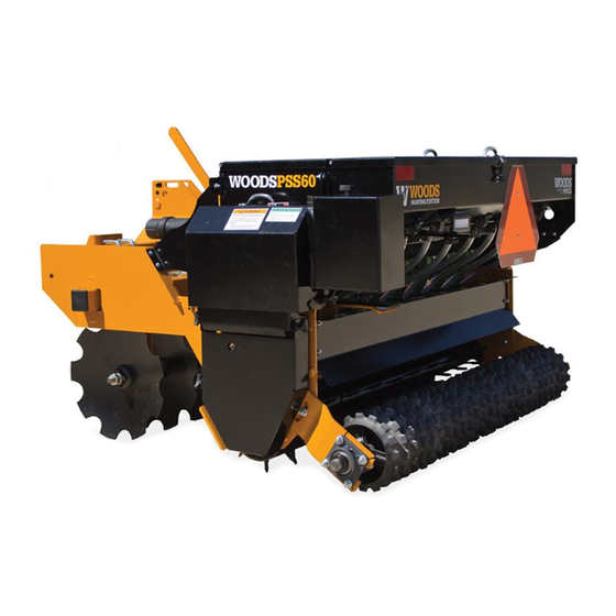
- Page 1 PRECISION SUPER SEEDER PSS48 PSS60 PSS72 PSS84...
-
Page 2: Introduction
TO THE OWNER: Read this manual before operating your Woods equipment. The information presented will prepare you to do a better and safer job. Keep this manual handy for ready reference. Require all operators to read this manual carefully and become acquainted with all adjustment and operating procedures before attempting to operate. -
Page 3: Table Of Contents
TABLE OF CONTENTS INTRODUCTION ..............2 SPECIFICATIONS . -
Page 4: Specifications
SPECIFICATIONS PSS48 PSS60 PSS72 PSS84 Working Width 49.25" 60" 72" 84" Overall Width (Maximum Configuration) 61.25" 72" 84" 96" Spike Roller Pins 1/2" x 1-3/4" 1/2" x 1-3/4" 1/2" x 1-3/4" 1/2" x 1-3/4" No. of Roller Pins (Front and Rear) Front roller Positions 0-20°... -
Page 5: Safety 5
SAFETY RULES ATTENTION! BECOME ALERT! YOUR SAFETY IS INVOLVED! A minimum 20% of tractor and equipment Safety is a primary concern in the design and weight must be on the tractor front wheels when manufacture of our products. Unfortunately, our attachments are in transport position. -
Page 6: Transportation
SAFETY RULES ATTENTION! BECOME ALERT! YOUR SAFETY IS INVOLVED! has been turned off. Hydraulic system leak-down, (Safety Rules continued from previous page) hydraulic system failures, mechanical failures, or Watch for hidden hazards on the terrain during movement of control levers can cause equipment operation. -
Page 7: Safety & Instructional Decals
Replacement safety decals can be ordered free from your Woods dealer. To locate your nearest dealer, check the Dealer Locator at www.WoodsEquipment.com, or in the United States and Canada call 1-800-319-6637. - Page 8 SAFETY & INSTRUCTIONAL DECALS ATTENTION! BECOME ALERT! YOUR SAFETY IS INVOLVED! Replace Immediately If Damaged! (Safety Decals continued from previous page) (Safety Decals continued from previous page) 2 - PN 1003751 1 - PN 55121 3 - PN 55122 4 - PN 15502 5 - PN 18868 8 - PN 1034504 9 - PN 1041910...
-
Page 9: Operation
SAFETY & INSTRUCTIONAL DECALS ATTENTION! BECOME ALERT! YOUR SAFETY IS INVOLVED! Replace Immediately If Damaged! (Safety Decals continued from previous page) 10 - PN W5669 12 - PN W19924 11 - PN 12777 13 - PN 614738 6 - PN 24611 Slow Moving Vehicle 14 - PN 614737 17 - PN 20106... - Page 10 OPERATION The operator is responsible for the safe operation of Front Rollers this seeder. The operator must be properly trained. When the front rollers are straight (Figure 1) and the Operators should be familiar with the equipment, the seeder is pulled forward, the large front pins will pene- tractor, and all safety practices before starting opera- trate the soil in a straight pushing action, and little dis- tion.
- Page 11 Front Disc Chain Drive Disconnect The front disc tool can be used to prepare a seedbed The Precision Super Seeder seed boxes can be without the need for a separate disc or tillage tool used engaged or disengaged so that any one seed box or all ahead of time.
-
Page 12: Attaching Ground Seeder To Tractor
A minimum 20% of tractor and equipment weight must be on the tractor front wheels when attachments are in transport position. Without this weight, front tractor wheels could raise up result- ing in loss of steering. The weight may be attained with front wheel weights, ballast in tires, front trac- tor weights or front loader. -
Page 13: Hitching Precision Super Seeder To Tractor
HITCHING PRECISION SUPER SEEDER 5. Attach the safety chain to the tractor as shown in Figure 10. Limit chain slack to only what is needed TO TRACTOR WITH TOW KIT for turning. Be sure to lock hook securely. Make sure shields and guards are properly installed and in good condition. - Page 14 PRECISION SUPER SEEDER ATTITUDE 4. Resume operation check performance. ADJUSTMENT Repeat as necessary. The Precision Super Seeder can be used as both a till- Drawbar Mounted age tool and a seeding tool. When used strictly as a till- age tool, a nose-down attitude will provide the most 1.
- Page 15 NOTICE: The 72" and 84" seeders use the front notch of the frame rail for the maximum roller angle (19° and 17° respectively). The 60" seeder uses the 2nd notch from the front for the maximum roller angle (20°). The 48" seeder uses the 3rd notch from the front for the maximum roller angle (20°).
- Page 16 10. Reverse this procedure to move front disc back as the size of the seed increases. Opening the con- cave ever further will also increase the seed rate. Seed into straight position. from the Primary seed box is dropped in front of the rear roller.
- Page 17 Figure 18. Seed Boxes IMPORTANT ■ Do not operate seeder in reverse. Operating seeder in reverse may result in damage to seed boxes and chain drive system. Figure 19. Transition Trays Filling the Seed Box seed cup must be restricted with seed in the seed box, place a piece of cardboard over the seed cup 1.
-
Page 18: Sample Seed Rate Charts
brace point in the covers spill guard notch. See 4. Lift brace and rotate to storage position. Close Figure 20. seed cover and engage cover latch. 3. Place seed in the seed box. SAMPLE SEED RATE CHARTS (STANDARD CHAIN DRIVE) NOTICE: For chain drives other than the standard drive, refer to the conversion charts for the multiplier to convert the application rate to the correct value. - Page 19 Legume Seed Rate Chart Legume Conversion Chart Chain Drive Multiply By Standard 40 Tooth Sprocket 0.75 Slow Kit 0.40 Super Slow Kit 0.25 Native Seed Rate Chart Native Conversion Chart Chain Drive - Left Side Multiply By Standard 40 Tooth Sprocket 0.75 Slow Kit 0.40...
- Page 20 DP16 Figure 21. Primary Seed Rate Adjustment Lever Figure 20. Seed Box Cover and Brace Seed Rate Adjustment Tractor speed and seed flow settings are critical for proper seed population. Use the calibration tray to adjust the seed cups for the desired seeding rate. Trac- tor speed (normally 2-5 mph) should be established so that uniform seed incorporation occurs with the action of the rollers.
- Page 21 Primary Seed Cup Concave Lever Adjustment Legume Seed Cup The Primary seed cup comes equipped with an adjust- The Legume seed box is equipped with PVC tubes to able concave to handle a wide variety of seed sizes. place the legume seed in the transition tray for the pri- For small seeds, including grass seeds, the concave mary seed box, ahead of the front roller.
- Page 22 Figure 27. Standard Drive Chains and Sprockets, Left Side Figure 28. Slow Drive Chains and Sprockets, P/N 1036395 (Rev. 9/20/2014) 22 Operation MAN0988 (11/5/2012)
- Page 23 Figure 29. Super Slow Drive Chains and Sprockets, P/N 1036396 Figure 30. Standard, Native Drive Chains and Sprockets, Right Side (Rev. 9/20/2014) Operation 23 MAN0988 (11/5/2012)
- Page 24 Cultipacker Procedure 1. Position tractor and seeder on a level surface. The optional cultipacker can be used to firm the seed bed for small seeds and increase seed to soil contact. 2. Adjust seed meter to closed position if applicable. The cultipacker is equipped to operate through an 3.
-
Page 25: Calibration Formula
5. Remove calibration tray (34 cu. in. capacity) from 8. Turn off engine and set parking brake. storage location. Install tray designated 9. Carefully remove calibration tray to retrieve collection slot and tighten against frame with two collected seed. Weigh seed and use formula to plastic nuts (check that calibration tray does not determine seed rate. -
Page 26: Transportation
TRANSPORTATION Transport Lock Up CAUTION IMPORTANT ■ Always transport with the cylinder in the full ■ Always raise unit and install transport lock extended, locked position. before transporting. Leak down or failure of mechanical/electrical or hydraulic system can 1. Fully extend cylinder. cause equipment to drop. -
Page 27: Owner Service 27
OWNER SERVICE REMOVING CULTIPACKER SHAFT FROM The information in this section is written for operators who possess basic mechanical skills. If you need help, FRAME your dealer has trained service technicians available. 1. Place cultipacker on level, dry surface, with the For your protection, read and follow the safety informa- cultipacker cast iron wheels on the ground. -
Page 28: Servicing Tires Safely
Figure 33. Lubrication Points SERVICING TIRES SAFELY Check wheels for low pressure, cuts, bubbles, dam- aged rims, or missing lug bolts and nuts. ARNING Never remove split rim assembly hardware (A) with the tire inflated. Do not attempt to mount a tire unless you have the proper equipment and experience to perform the job. -
Page 29: Cleaning
● parts. Sand down scratches and the edges of areas of ● Replace any safety decals that are missing or not missing paint and coat with Woods spray paint of ● readable. matching color (purchase from your Woods dealer). Periodically or Before Extended Storage Replace any safety decals that are missing or not ●... -
Page 30: 30 Assembly
Assembly of this equipment is the responsibility of the 8. Install bent pin and hair pin clip on disc slide in Woods dealer. It should be delivered to the owner com- fourth hole from rear. pletely assembled, lubricated, and adjusted for normal operating conditions. - Page 31 19. Install left hand shield with 1/4” hardware to 4. Loosen 3/4” u-bolts and flanged nuts from factory- primary box shield. installed hitch brackets. 20. Install right hand shields. 5. Position tongue between factory 3-point hitch brackets. Slide factory hitch brackets together until Legume Seed Box (For Illustration, see page 42) tongue is centered on frame and fit tightly between brackets.
- Page 32 oriented properly for readability from alongside NOTICE: Clamping the long hose by the ferrule will seeder. Install bent retainer pin with hairpin clip. provide additional support to the routing. See Figure 37A. 14. Install parking jack on mounting tube on tongue and pin in place.
-
Page 33: Dealer Check Lists 33
DEALER CHECK LISTS PRE-DELIVERY CHECK LIST ___ Show customer the safe, proper procedures to be used when mounting, dismounting, and storing (DEALER’S RESPONSIBILITY) equipment. Inspect the equipment thoroughly after assembly to ___ Make customer aware of optional equipment ensure it is set up properly before delivering it to the available so that customer can make proper customer. - Page 34 NOTES 34 Dealer Check Lists MAN0988 (11/5/2012)
-
Page 35: Parts Index
PARTS INDEX PRECISION SUPER SEEDER PSS48 PSS60 PSS72 PSS84 Main Frame and Roller Assembly .......36 - 37 Primary Seed Box Assembly . - Page 36 PSS48, PSS60, PSS72 & PSS84 MAIN FRAME & ROLLER ASSEMBLY (Rev. 4/24/2018) 36 Parts MAN0988 (11/5/2012)
- Page 37 PSS48, PSS60, PSS72, PSS84 MAIN FRAME & ROLLER ASSEMBLY PARTS LIST PSS48 PSS60 PSS72 PSS84 DESCRIPTION ………… ………… ………… ………… Frame, seeder 103877648RP 103877660RP 103877672RP 103877684RP Spiked drive roller W301117* W301117* W301117* W301117* 3/8 NC x 1-3/4 carriage bolt ZP 20A920 20A920 20A920...
- Page 38 PSS48, PSS60, PSS72, PSS84 PRIMARY SEED BOX ASSEMBLY (Rev. 1/08/2020) 38 Parts MAN0988 (11/5/2012)
- Page 39 PSS48, PSS60, PSS72, PSS84 PRIMARY SEED BOX PARTS LIST PSS48 PSS60 PSS72 PSS84 DESCRIPTION 103517948RP 103517960RP 103517972RP 103517984RP Seedbox, Primary 103569848RP 103569860RP 103569872RP 103569884RP Cover, seedbox Primary, Native 1035663RP 1035663RP 1035663RP 1035663RP Mount, bearing Primary 1034739RP 1034739RP 1034739RP 1034739RP Tube, transmission 1034694 1034694 1034694...
- Page 40 PSS48, PSS60, PSS72, PSS84 PRIMARY SEED BOX PARTS LIST (CONTINUED) PSS48 PSS60 PSS72 PSS84 DESCRIPTION 1035651RP 1035651RP 1035651RP 1035651RP Sleeve, .56 x .75 x .75 854* 854* 854* 854* 1/2 flat washer, ZP 27635* 27635* 27635* 27635* 1/2 NC x 3-1/2 carriage bolt 62043* 62043* 62043*...
- Page 41 PSS48, PSS60, PSS72, PSS84 FRONT SPIKE ROLLER OPTION PSS48 PSS60 PSS72 PSS84 DESCRIPTION 103876648RP 103876660RP 103876672RP 103876684RP Front roller 1038680RP 1038680RP 1034677RP 1034677RP Mount, bearing 20A920 20A920 20A920 20A920 1" bearing w/ housing 14350* 14350* 14350* 14350* 3/8 NC flanged lock nut W301117* W301117* W301117*...
- Page 42 PSS48, PSS60, PSS72, PSS84 LEGUME SEED BOX OPTION (Rev. 1/08/2020) 42 Parts MAN0988 (11/5/2012)
- Page 43 PSS48, PSS60, PSS72, PSS84 LEGUME SEED BOX PARTS LIST PSS48 PSS60 PSS72 PSS84 DESCRIPTION 103517848RP 103517860RP 103517872RP 103517884RP Seedbox, Legume 14350* 14350* 14350* 14350* 3/8 NC flanged lock nut 103569948RP 103569960RP 103569972RP 103569984RP Cover, Legume seedbox 20A635 20A635 20A635 20A635 Lid, handle 1001994* 1001994*...
- Page 44 PSS48, PSS60, PSS72, PSS84 NATIVE SEED BOX OPTION (Rev. 4/24/2018) 44 Parts MAN0988 (11/5/2012)
- Page 45 PSS48, PSS60, PSS72, PSS84 NATIVE SEED BOX PARTS LIST PSS48 PSS60 PSS72 PSS84 DESCRIPTION 103518048RP 103518060RP 103518072RP 103518084RP Seedbox, Native 103569848RP 103569860RP 103569872RP 103569884RP Cover, Native Primary seedbox 20A635 20A635 20A635 20A635 Lid, handle 1001978* 1001978* 1001978* 1001978* 3/16 No. 63 blind rivet 1035225 1035225 1035225...
- Page 46 PSS48, PSS60, PSS72, PSS84 NATIVE SEED BOX PARTS LIST (CONTINUED) PSS48 PSS60 PSS72 PSS84 DESCRIPTION 1038744 1038744 1038744 1038744 Plug, 1/4" 10378 10378 10378 10378 Bolt, 1/4 x 1 4378 4378 4378 4378 Washer, 5/16 flat 73758 73758 73758 73758 Cable, shield Washer, 3/8 flat Standard hardware, obtain locally...
- Page 47 PSS48, PSS60, PSS72, PSS84 FRONT DISC OPTION (SERIAL NO. 1285000 & BELOW) PSS48 PSS60 PSS72 PSS84 DESCRIPTION 1011274 (6) 1011274 (8) 1011274 (10) 1011274 (12) 18" notched blade 1011322 1011322 1011322 1011322 Washer, disc bumper 1035248 1011299 1011277 1011279 Axle, disc 1011324 1011324 1011324...
- Page 48 PSS48, PSS60, PSS72, PSS84 CAST IRON CULTIPACKER OPTION PSS48 PSS60 PSS72 PSS84 DESCRIPTION 103465048RP 103465060RP 103465072RP 103465084RP Shaft, cultipacker 1033740 1033740 1033740 1033740 1.38 flanged 4 bolt bearing 1035210RP 1035210RP 1035210RP 1035210RP Mount, cultipacker 1034676 1034676 1034676 1034676 1-3/4 clamp 1034651 (22) 1034651 (26) 1034651 (32)
- Page 49 PSS48, PSS60, PSS72, PSS84 NYLON CULTIPACKER OPTION PAGE 42 PSS48 PSS60 PSS72 PSS84 DESCRIPTION 103878048RP 103878060RP 103878072RP 103878084RP Shaft, cultipacker 1033740 1033740 1033740 1033740 1.38 flanged 4 bolt bearing 1038699RP 1038699RP 1038699RP 1038699RP Arm, cultipacker 1034676 1034676 1034676 1034676 1-3/4 clamp 1038781P (20) 1038781P (25) 1038781P (30)
- Page 50 PSS48, PSS60, PSS72, PSS84 SCRAPERS SPIKED ROLLER OPTION PSS48 PSS60 PSS72 PSS84 DESCRIPTION 1036465RP 1036465RP 1036465RP 1036465RP Scraper, mount, spiked front, LH 103642948RP 103642960RP 103642972RP 103642984RP Scraper, spiked front 1036464RP 1036464RP 1036464RP 1036464RP Scraper, mount, spiked front, RH 1036455RP 1036455RP 1036455RP 1036455RP Scraper, mount, middle LH...
- Page 51 PSS48, PSS60, PSS72, PSS84 SCRAPERS - DISC & SPIKED DRIVE ROLLER OPTION PSS48 PSS60 PSS72 PSS84 DESCRIPTION 1038754RP 1038754RP 1038754RP 1038754RP Scraper, disc mount, RH 1038752RP (1) 1038752RP(1) 1038752RP (2) 1038752RP (3) Scraper, disc link, LH 1038751RP 1038751RP 1038751RP 1038751RP Scraper, disc mount, LH 1038753RP (1) 1038753RP (1)
- Page 52 PSS48, PSS60, PSS72, PSS84 SCRAPERS - CAST IRON CULTIPACKER OPTION PSS48 PSS60 PSS72 PSS84 DESCRIPTION 103642648RP 103642660RP 103642672RP 103642684RP Scraper, cultipacker, cast iron 1036427RP 1036427RP 1036427RP 1036427RP Mount, scraper, cultipacker, cast iron, LH 1036428RP 1036428RP 1036428RP 1036428RP Mount, scraper, cultipacker, cast iron, RH 6697* 6697* 6697*...
- Page 53 PSS48, PSS60, PSS72, PSS84 SCRAPER - NYLON CULTIPACKER OPTION PSS48 PSS60 PSS72 PSS84 DESCRIPTION 103879248RP 103879260RP 103879272RP 103879284RP Scraper, cultipacker, nylon - rear 1038797RP 1038797RP 1038797RP 1038797RP Mount, scraper, cultipacker, nylon LH 1038798RP 1038798RP 1038798RP 1038798RP Mount, scraper, cultipacker, nylon RH 6697* 6697* 6697*...
- Page 54 PSS48, PSS60, PSS72, PSS84 ROW UNITS PSS48 PSS60 PSS72 PSS84 DESCRIPTION 103877148RP 103877160RP 103877172RP 103877184RP Guide, row unit 1038769RP (1) 1038769RP (1) 1038769RP (2) 1038769RP (2) Mount, row guide, LH 1038768RP (1) 1038768RP (1) 1038768RP (2) 1038768RP (2) Mount, row guide, RH 839* (2) 839* (2) 839* (4)
- Page 55 1036395 SLOW CHAIN DRIVE ACCESSORY PARTS (see Figure 28 in OPERATION) NOTE: Bearing mount and shields are hidden for component identification PART DESCRIPTION 1036379 WA, sprocket RC40 15-50 in. bore 1036402 Chain, seeder main A2040 40 link 1036422 Sprocket, RC40 22th 3/4 bore 1036404 Chain, Legume box A2040 54 links 1036405...
- Page 56 1036396 SUPER SLOW CHAIN DRIVE ACCESSORY PARTS (see Figure 29 in OPERATION) NOTE: Bearing mount and shields are hidden for component identification PART DESCRIPTION 1036376 WA, sprocket RC40 15-50 1 in. bore 1036401 Chain, seeder main A2040 38 link 1036422 Sprocket, RC40 22th 3/4 bore 1036404 Chain, Legume box A2040 54 links...
- Page 57 PLATFORM ACCESSORY PSS48 PSS60 PSS72 PSS84 DESCRIPTION ------- 1038757RP 1038757RP 1038757RP Platform, seeder ------- 1038762RP 1038762RP 1038762RP Clamp, platform ------- 10380* 10380* 10380* 1/2 NC x 4 HHCS, GR5 ------- 11900* 11900* 11900* 1/2 NC flanged lock nut HHCS - Hex Head Cap Screw Standard Hardware, Obtain Locally (Rev.
- Page 58 604387 LIGHT KIT OPTION PART DESCRIPTION 599771 Main harness, 4 ft 1040277 AG enhancer module 599772 Rear harness, 6 ft RH 1040275 LED AG combo lamp LH 1040276 LED AG combo lamp RH 602513RP Angle, plug holder, 7 pin 14350 Nut lock 3/8 NC flange 6697 Bolt crg 3/8 NC x GR5 ZP...
- Page 59 PSS48, PSS60, PSS72, PSS84 TOW KIT OPTION PSS48 PSS60 PSS72 PSS84 DESCRIPTION 609306RP 609306RP 609306RP 609306RP Tow tongue GS 609708 609708 609708 609708 Tow hitch 6110148RP 6110160RP 6110172RP 6110184RP Tow carrier LH 6110248RP 6110260RP 6110272RP 6110284RP Tow carrier RH 611103RP 611103RP 611103RP 611103RP...
- Page 60 PSS48, PSS60, PSS72, PSS84 TOW KIT HOSE ROUTING PSS48 PSS60 PSS72 PSS84 DESCRIPTION 17628 17628 17628 17628 1/4 NPT x 108 hose 34221 34221 1/4 NPT x 65 hose (PSS72 / 84 only) 31237 31237 1/4 NPT x 47 hose (PSS48 / 60 only) 597269 597269 597269...
-
Page 61: Appendix 61
BOLT TORQUE CHART Always tighten hardware to these values unless a different torque value or tightening procedure is listed for a specific application. Fasteners must always be replaced with the same grade as specified in the manual parts list. Always use the proper tool for tightening hardware: SAE for SAE hardware and Metric for metric hardware. Make sure fastener threads are clean and you start thread engagement properly. -
Page 62: Bolt Size Chart & Abbreviations
BOLT SIZE CHART NOTE: Chart shows bolt thread sizes and corresponding head (wrench) sizes for standard SAE and metric bolts. SAE Bolt Thread Sizes 5/16 Metric Bolt Thread Sizes 10MM 12MM 14MM 16MM 18MM ABBREVIATIONS AG .............. Agriculture MPa ............Mega Pascal ASABE ....American Society of Agricultural &... -
Page 63: Index 63
INDEX ASSEMBLY Seeding Operation 16 Calibration Tray 24 Dealer Set-Up Instructions 30 Cultipacker 24 Optional Accessories 30 Filling the Seed Box 17 Cultipacker 31 Legume Seed Cup 21 Front Disc 30 Primary Seed Cup Concave Lever Adjustment 21 Front Spike Roller 30 Sample Seed Rate Chart 18 Legume Seed Box 31 Seed Rate 20... -
Page 64: Repair Parts Warranty
Woods logo are trademarks of Woods Equipment Company. All other trademarks, trade names, or service marks not owned by Woods Equipment Company that appear in this manual are the property of their respective companies or mark holders. Specifications subject to change without notice. -
Page 65: Product Warranty
The limited warranty covers any defects in the material and/or workmanship. Following the proper, recommended installation by an authorized Woods Dealer and normal use of a Woods mounting and backhoe or loader, if a tractor incurs damage resulting from the attachment, Woods will cover the existing tractor warranty in the event the manufacturer voids its tractor warranty because of the attachment. - Page 66 Woods logo are trademarks of Woods Equipment Company. All other trademarks, trade names, or service marks not owned by Woods Equipment Company that appear in this manual are the property of their respec- tive companies or mark holders. Specifications subject to change without notice.