Table of Contents
Advertisement
Quick Links
Advertisement
Table of Contents

Related Manuals for Woods DS8.30


Summary of Contents for Woods DS8.30
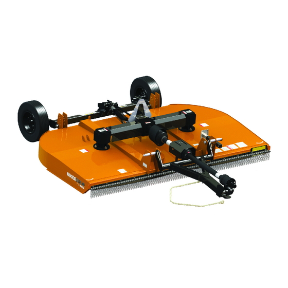
- Page 1 ROTARY CUTTER DS8.30 DS10.40...
-
Page 2: Introduction
TO THE OWNER: Read this manual before operating your Woods equipment. The information presented will prepare you to do a better and safer job. Keep this manual handy for ready reference. Require all operators to read this manual carefully and become acquainted with all adjustment and operating procedures before attempting to operate. -
Page 3: Table Of Contents
GEARBOX REPAIR - DS8.30 ......28 SEAL REPAIR - DS8.30 ......28 SPINDLE GEARBOX REPAIR - DS10.40 . -
Page 4: Specifications
If you would like to receive a free Spanish language translation of the Safety Rules section of this Si no lee Ingles, pida ayuda a manual, plus a set of Spanish language safety decals, please contact your local Woods dealer. alguien que si lo lee para que le traduzca las medidas de seguridad. -
Page 5: Safety 5
BE SAFE! BE ALERT! BE ALIVE! BE TRAINED Before Operating Mowers! Safety Training Does Make a Difference. ASSOCIATION OF EQUIPMENT MANUFACTURERS Watch a Mower Safety Video Online The AEM (Association of Equipment Manufacturers) offers a safety training video, Industrial and Agricultural Mower Safety Practices. The 22-minute video can be viewed online for free at TheAEMStore, https://youtu.be/EuktqJNAjhc It reinforces the proper procedures to follow while operating your mowing... - Page 6 Also, available from the Association of Equipment Manufacturers: A large variety of training materials (ideal for groups) are available for a nominal charge from AEM. Following is a partial list: Training Package for Rotary Mowers/Cutters-English Contains: DVD & VHS (English) Guidebook for Rotary Mowers/Cutters (English) AEM Industrial/Agricultural Mower Safety Manual (English) AEM Agricultural Tractor Safety Manual (English)
-
Page 7: Safety Rules
SAFETY RULES ATTENTION! BECOME ALERT! YOUR SAFETY IS INVOLVED! PREPARATION Safety is a primary concern in the design and man- ■ Check that all hardware is properly installed. ufacture of our products. Unfortunately, our efforts Always tighten to torque chart specifications to provide safe equipment can be wiped out by an unless instructed otherwise in this manual. -
Page 8: Operation
SAFETY RULES ATTENTION! BECOME ALERT! YOUR SAFETY IS INVOLVED! ■ Make sure shields and guards are proper- ■ Power unit must be equipped with ROPS or ly installed and in good condition. Replace if ROPS cab and seat belt. Keep seat belt secure- damaged. -
Page 9: Maintenance
SAFETY RULES ATTENTION! BECOME ALERT! YOUR SAFETY IS INVOLVED! MAINTENANCE ■ Frequently check blades. They should be sharp, free of nicks and cracks, and securely fastened. ■ Before dismounting power unit or perform- ■ Do not handle blades with bare hands. Careless ing any service or maintenance, follow these or improper handling may result in serious steps: disengage power to equipment, lower... -
Page 10: Safety & Instructional Decals
Replace safety decals if they are missing or illegible. Replacement safety decals can be ordered free from your Woods dealer, or in the United States and Canada call 1-800-319-6637. - Page 11 SAFETY & INSTRUCTIONAL DECALS ATTENTION! BECOME ALERT! YOUR SAFETY IS INVOLVED! Replace Immediately If Damaged! 5 - PN 1003751 6 - PN 15503 7 - PN 18865 8 - PN 18866 WARNING WARNING DO NOT EXCEED PTO SPEED OF FALLING OFF CAN RESULT IN BEING RUNOVER. ■...
- Page 12 SAFETY & INSTRUCTIONAL DECALS ATTENTION! BECOME ALERT! YOUR SAFETY IS INVOLVED! Replace Immediately If Damaged! 14 - PN 1004991 13 - PN W19924 15 - PN 33347 PN 1006348 (LOCATED ON WHEEL RIMS) WARNING EXPLOSION HAZARD RELEASE ALL AIR PRESSURE BEFORE LOOSENING BOLTS. FAILURE TO DO SO COULD RESULT IN SERIOUS INJURY OR DEATH.
-
Page 13: Operation 13
OPERATION The operator is responsible for the safe operation TRACTOR STABILITY of the cutter. The operator must be properly trained. Operators should be familiar with the cutter, the tractor, WARNING and all safety practices before starting operation. Read the safety rules and safety decals on pages 7 to 12. ■... -
Page 14: Connect Cutter To Tractor (Mounted)
1" pin supplied with tractor mum turn that should be made. top link. See Figure 2. DS8.30 Category 1 & 2 Quick Hitch 1. Insert lower hitch pins (1), 1-1/8" OD sleeves (2), and 1-7/16" OD sleeves (3) through mast plates. -
Page 15: Driveline Adjustment
(less than 4" overlap) contact 2. The upper hook on the quick hitch will engage the your Woods dealer for a longer drive. 1-1/4" sleeve (7) between break links (8) as shown for Category 2. Break links and sleeve will need to... - Page 16 4. Cut the shield to the overall dimension. 4" Maximum Distance Between Tractor PTO Shaft and Gearbox Input Shaft CD7155-1 Figure 4. 4 Inch Minimum Overlap Shortening Driveline Figure 7. Cut Shield 1. Separate driveline into two halves and connect them to the tractor PTO and gearbox.
-
Page 17: Cutting Height Adjustment
CUTTING HEIGHT ADJUSTMENT Adjust the position of the tailwheel arms between the tailwheel height adjustment brackets to obtain a dis- NOTICE tance greater than 2-3/4" at position “B” Adjust top link to provide 1-1/2" of clearance between ■ Avoid ground contact with blades. Striking the break link (2) and the rear lift links. -
Page 18: Tractor Operation
TRACTOR OPERATION Cutter Operation When beginning operation of the cutter, make sure that Use care when operating around tree limbs and other all persons are in a safe location. Slowly move into the low objects. material with the tractor PTO set at 540 rpm. Use care and reduce ground speed on rough terrain. -
Page 19: Transporting
TRANSPORTING ON PULL-TYPE CUTTERS: ■ Raise cutter and block securely. Block wheels WARNING and raise tongue with jack. Disconnect hydraulic lines to optional cylinder. Disconnect driveline and secure up off the ground. ■ The maximum transport speed for towed and semi-mounted machines is 20 mph (32 km/h). -
Page 20: 20 Owner Service
OWNER SERVICE 2. Consider the overall stability of the blocked unit. The information in this section is written for operators who possess basic mechanical skills. If you need help, Just placing jackstands underneath will not ensure your dealer has trained service technicians available. your safety. -
Page 21: Blade Servicing
MOUNTED MOUNTED CD8560 DESCRIPTION FREQUENCY DESCRIPTION FREQUENCY Driveline U-Joint 10 hrs. Side Drive Yoke 40 hrs. Telescoping Shaft 10 hrs. Gearbox (Check Oil Level) Daily CV Body Assembly 10 hrs. Tailwheel Spindle 20 hrs. (10 pumps minimum) Caster Wheel Swivel 40 hrs. -
Page 22: Slip Clutch Adjustment
3. Align crossbar (5) with blade access hole in cut- DS8.30 - 3-Point Mounted ter frame. Apply a liberal coating of Never Seez or equivalent to blade pin and crossbar hole. Make 1. Turn off tractor engine and remove key. -
Page 23: Rubber Disk Replacement
DS8.30 3-Point Mounted Outer Plates 1.26" DS8.30 Pull-Type DS10.40 Pull-Type 1/8" DS10.40 3-Point Mounted 1. Flange yoke 2. Friction disc 3. Hub, 1-3/8" round bore 4. Thrust plate 5. Belleville spring plate 6. 10 mm x 1.5P x 55 mm Cap screw 7. -
Page 24: Shielding Repair
6. Shaped washer 7. Bushing 8. M16-2.0P x 65 mm HHCS 9. M16-2.0P x 90 mm HHCS A. Complete Flex Coupler Drive, DS8.30 10. M16-2.0P Lock nut B. Complete Flex Coupler Drive, DS10.40 11. M8 x 1.0P Grease fitting CD8564 Figure 15. -
Page 25: Cleaning Cutter
■ Inspect machine and replace worn or damaged parts. ■ Sand down scratches and the edges of areas of missing paint and coat with Woods spray paint of matching color (purchase from your Woods dealer). ■ Replace any safety decals that are missing or not readable (supplied free by your Woods dealer). -
Page 26: 26 Troubleshooting
TROUBLESHOOTING PROBLEM POSSIBLE CAUSE SOLUTION Does not cut Dull blades Sharpen blades. Worn or broken blades Replace blades. (Replace in pairs only.) Incorrect PTO speed Set at rated PTO speed. Ground speed too fast Reduce ground speed. Drive not functioning (blades do Check drive shaft connection. -
Page 27: Dealer Service 27
DEALER SERVICE The information in this section is written for dealer ser- Seal Replacement vice personnel. The repair described here requires special skills and tools. If your shop is not properly Recommended sealant for gearbox repair is Permatex ® equipped or your mechanics are not properly trained in Aviation 3D Form-A-Gasket or equivalent. -
Page 28: Gearbox Repair - Ds8.30
GEARBOX REPAIR - DS8.30 14. Inspect vertical and horizontal shafts for grooves, nicks, or bumps in the areas where the seals seat. (Figure 19) Resurface any damage with emery cloth. 15. Inspect housing and caps for cracks or other NOTE: Repair to this gearbox is limited to replacing damage. - Page 29 13 12 21. Ball bearing 22. Sealing washer CD7690 23. M8 Lock washer 24. M8 x 1.5 x 25 Cap screw 25. Bearing Cup and Cone 26. Shim Kit Figure 19. DS8.30 Gearbox Assembly Dealer Service 29 MAN1167 ( 07/25/2023 )
-
Page 30: Spindle Gearbox Repair - Ds10.40
SPINDLE GEARBOX REPAIR - DS10.40 15. Support housing upside down (top cover surface) and remove bearing (15) by using a punch and (Figure 20) hammer from the bottom side of the housing. 16. Inspect gears for broken teeth and wear. Some wear NOTE: Replacing gears, shafts, bearings, and seals is normal and will show on loaded side. - Page 31 1. Gearbox housing 2. Cap screw 8 mm x 14 (8.8) 3. Vent plug 4. Top cover 5. Shim kit 6. Crown gear 7. Bearing cup & cone 8. Cotter pin B6 x 60 mm 9. Snap ring 10. Seal 11.
-
Page 32: Splitter Gearbox Repair
Assemble Gearbox - DS10.40 16. Press in input oil seal (10), using tube of correct di- ameter. Be careful not to damage seal lip. 1. Clean housing, paying specific attention to areas 17. Press oil cap (24) on to cover the rear of housing, where gaskets will be installed. - Page 33 1. Gearbox 2. Lock nut 3. M10 x 1.5 x 22 Cap screw 4. Cross shaft 5. Shim, 45.3 x 65.3 x 2.5 6. Vent plug 7. Crown gear 8. Pinion gear 9. Shim, 45.3 x 65.3 x 1 10. Key, 14 x 9 x 40 11.
-
Page 34: Side Drive Service
6. Shaped washer 7. Bushing 8. M16-2.0P x 65 mm HHCS 9. M16-2.0P x 90 mm HHCS A. Complete Flex Coupler Drive, DS8.30 10. M16-2.0P Lock nut B. Complete Flex Coupler Drive, DS10.40 11. M8 x 1.0P Grease fitting CD8564 Figure 22. -
Page 35: Crossbar
CROSSBAR Crossbar Removal 1. It is necessary to gain access to bottom side of cutter for crossbar removal. See BLOCKING METHOD, page 20. NOTE: You will need to use either the puller screw (Item 6, Figure 23) or a small hydraulic jack to re- move the crossbar. - Page 36 Crossbar Installation 2. Install crossbar (5) on splined shaft. Install washer (18), castle nut (19), and cotter pin (20). Torque nut 1. Using emery cloth (220 or finer), remove surface to 450 lbs-ft. rust, and foreign material from hub, splined gearbox 3.
-
Page 37: Universal Joint Repair
UNIVERSAL JOINT REPAIR 3. Clamp cup in vise as shown in Figure 30 and tap on yoke to completely remove cup from yoke. Repeat Step 2 and Step 3 for opposite cup. 1. Yoke 2. Bearing cup 3. Retaining ring 4. -
Page 38: Servicing Tires Safely
U-Joint Assembly SERVICING TIRES SAFELY 1. Place seals securely on bearing cups. Insert cup into Used Aircraft Tires (Figure 33) yoke from outside and press in with hand pressure as far as possible. Insert journal cross into bearing WARNING cup with grease fitting away from shaft. Be careful not to disturb needle bearings. -
Page 39: Assembly 39
DEALER SET-UP INSTRUCTIONS Install Tongue 1. Remove lower hitch pins (2) and klik pins (4) from These instructions are for the assembly of the DS8.30 mast plates. and DS10.40 mounted and pull-type cutters. Many of the procedures apply to all units. When an instruction 2. - Page 40 26. 1/4 x 1-1/2 Cotter pin 40. Grease fitting (DS10.40 only) 13. SMV Emblem 27. 1/2 NC x 3 HHCS 14. Parking jack 28. 1/2 NC x 5-1/4 HHCS Figure 34. DS8.30 & DS10.40 Pull-Type Assembly 40 Assembly MAN1167 ( 07/25/2023 )
-
Page 41: Assemble Ds8.30 & Ds10.40 3-Point Mounted Cutter
19. 1/4-28 Straight grease fitting (DS10.40 only) 8. Sleeve, 5/8 x 1 x 11/16 20. 1/2 Flat washer 33. 5/8 NC x 7 HHCS (DS8.30 (DS8.30 only) 21. 1/2 NC x 1 HHCS only) 8. Sleeve, 5/8 x 1 x 13/16 22. -
Page 42: Fill Gearboxes
3. Rear band 4. Front reflector bracket 5. 3/8 NC x 1-1/4 Carriage bolt 6. 3/8 NC x 1 Carriage bolt 7. 3/8 NC Flange lock nut Figure 36. DS8.30 & DS10.40 Rubber Shield Installation 42 Assembly MAN1167 ( 07/25/2023 ) -
Page 43: Install Chain Or Rubber Shielding
5. 5/16 - 4 link chain 6. .243 Dia bent pin 7. .243 Dia bent pin 8. 3/8 NC x 1 Carriage bolt 9. 3/8 NC Flange lock nut Figure 37. DS8.30 & DS10.40 Optional Chain Shielding Installation Assembly 43 MAN1167 ( 07/25/2023 ) -
Page 44: 44 Dealer Checklists
DEALER CHECKLISTS DEALER PRE-DELIVERY CHECKLIST DELIVERY CHECKLIST (DEALER’S RESPONSIBILITY) (DEALER’S RESPONSIBILITY) Show customer how to make adjustments. Inspect cutter thoroughly after assembly to make sure Describe the options available for this cutter and it is set up properly before delivering it to the customer. explain their purpose. -
Page 45: Parts Index
WHEEL & TIRE ASSEMBLY ......61 DS8.30 & DS10.40 BELT SHIELDING ......62 DS8.30 &... - Page 46 DS8.30 / DS10.40 MAIN FRAME ASSEMBLY 34 - Complete decal set 35 - Safety decal set 36 - Spanish safety decal set CD8561 25, 26 46 Parts MAN1167 ( 07/25/2023 )
- Page 47 DS8.30 / DS10.40 MAIN FRAME PARTS LIST PART DESCRIPTION PART DESCRIPTION Spindle gearbox (DS8.30) 39323 M30-2.0P Castle nut (DS10.40) 1032585RP (See page 56) -or- 64803RP * 3/16 x 2 Cotter pin Spindle gearbox (DS10.40) 58803 66840RP 3/8 NC Knob (See page 57) 3/4 Hardened flat Splitter gearbox (DS8.30)
- Page 48 3132RP * NC Hex nut 1041677 Stub shaft (DS10.40) 1003606RP NC x 6 HHCS, GR5 1041676 CV Drive (DS8.30) (See page 59) 34279RP NC Hex lock nut 1040720 CV Drive (DS10.40) (See page 60) M12-1.75P x 30 mm 62542 1009234RP SMV Bracket HHCS (DS8.30) -or-...
- Page 49 DS8.30 & DS10.40 MOUNTED ASSEMBLY 20 21 CD8563 PART DESCRIPTION PART DESCRIPTION 57134RP A-Frame bar (DS8.30) -or- 1030523 M24-2.0P Axle bolt 1040701RP A-Frame bar (DS10.40) 12296 * 1/4-28 Straight grease fitting 1040654RP Break link ----- * 1/2 Flat washer 1040655RP Lift arm (DS8.30) -or-...
- Page 50 DS8.30 SPLITTER GEARBOX ASSEMBLY 23, 24, 25 5, 6, 7 13, 14, 15 CD8644 PART DESCRIPTION PART DESCRIPTION 1043025 Complete gearbox Spacer, 41.5 x 47.5 x 8.3 Gearbox housing Snap ring, 40 x 2.5 Retaining ring 20890 Ball bearing, 6207...
- Page 51 DS10.40 SPLITTER GEARBOX ASSEMBLY 1 - Complete Gearbox CD6664 PART PART DESCRIPTION DESCRIPTION 1008192 Complete gearbox 1008148 Bearing cup and cone 1008130 Lock nut 1008149 Input shaft 1-3/4 20 spline 39274 * 16 M10 x 1.5 x 22 mm Cap screw 1008151 Housing extension 1008131...
- Page 52 DS8.30 SPINDLE GEARBOX ASSEMBLY Use Silicone Sealer Between Cap and Housing 10, 11 CD7690-1 PART DESCRIPTION PART DESCRIPTION 1032585RP Gearbox repair assembly 1018328RP Output seal Housing 1038357 Output cap 1019632 Inspection cover Output bearing spacer 22 Tooth gear Output shaft and pinion...
- Page 53 DS10.40 SPINDLE GEARBOX ASSEMBLY 1 - Complete Gearbox CD6665 PART PART DESCRIPTION DESCRIPTION 58803 Complete gearbox 39263 Bearing, cup & cone 57150 * M8-1.25P x 14 mm HHCS 39289RP Seal, 50 x 90 x 10 57076 1/2 Vent plug 57338 Screen protection 57139 Cover...
- Page 54 DS8.30 / DS10.40 FLEXIBLE COUPLER ASSEMBLY CD8564 DS8.30 DS10.40 PART DESCRIPTION 1040670 ----- Complete flex coupler drive (DS8.30) 1009207 ----- Complete flex coupler drive (DS10.40) 1008143 Yoke, 1-3/8 6-spline 1008147 ----- Yoke, 1-3/4 20 spline ----- Single yoke & tube assembly ----- Double yoke &...
- Page 55 DS8.30 CV DRIVE ASSEMBLY CD8635 22 23 PART DESCRIPTION PART DESCRIPTION 1041676 Complete CV drive 38353 Yoke, outer profile 40589 Slide lock repair kit 38352 U-Joint repair kit 44671 Yoke, QD CV 1-3/8 - 6 spline 1027217 Flange yoke 1041684...
- Page 56 DS10.40 CV DRIVE ASSEMBLY CD7035C PART DESCRIPTION 1040720 Complete CV drive 19851 Slide lock repair kit 1032289 Yoke QD CV 1-3/8 - 6 1032290 CV U-Joint repair kit Cat 4 35E 1032291 CV Body with fitting 1032292 Yoke and shaft CV 1.31-20 spline 1024636 Drive shield bearing kit WALTERSCHEID...
- Page 57 DS10.40 REAR FIXED LENGTH DRIVE ASSEMBLY 15 16 CD8636 PART DESCRIPTION 1041677 Drive assembly complete 1041682 Drive without shield 38352 U-Joint cross & bearing kit 1019114 Friction clutch 40766 Bearing ring 40767 Support bearing 18864RP Decal, danger, rotating driveline 33347RP Decal, danger, guard missing 40778 Screw, (package of 10)
- Page 58 DS8.30 SLIP CLUTCH DRIVE ASSEMBLY CD8640 PART DESCRIPTION PART DESCRIPTION 1040710 Complete drive assembly 1043042 Clutch spring Complete collar yoke, 1028779 Flanged yoke 1028775 1-3/8 - 6 spline 1028780 Bushing 36990 U-Joint cross & bearing kit 1028781 Clutch lining ring 53464 Yoke &...
- Page 59 DS10.40 SLIP CLUTCH DRIVE ASSEMBLY A - Complete Drive Assembly CD5775 PART DESCRIPTION PART DESCRIPTION 57413RP Complete drive assembly 40779 Grease fitting, (package of 10) 40589 Slide lock collar repair kit 40574 Yoke, 1-3/8 - 6 spline 57268 Outer guard half, complete 110RP U-joint cross &...
- Page 60 DESCRIPTION 1040726RP Tongue, WA (DS8.30) -or- 1040721 Tongue, WA (DS10.40) 1038933 Hitch, Cat 1 clevis (DS8.30) -or- 1038085RP Hitch, Cat 2 clevis (DS10.40) 13087 Sleeve, HT 3/4 x 1 x 9/16 28873 3/4 ID x 1-1/2 OD x 1/4 Washer...
- Page 61 WHEEL & TIRE ASSEMBLY 15" Rim for Pneumatic Tire STYLE A STYLE B CD6885 Severe Duty Ag Tire & Rim Solid Tire & Rim PART DESCRIPTION PART DESCRIPTION Heavy hub assembly - Style A 15" Rim for pneumatic 1017050RP 1017088 (includes items 2 - 15) tire - 5 bolt -or- Hub assembly - Style B...
- Page 62 DS8.30 / DS10.40 BELT SHIELDING CD8567 DS8.30 DS10.40 PART DESCRIPTION PART DESCRIPTION 1040657 Front rubber deflector 1040706 Front rubber deflector 1043035 Front belt bracket 1043045 Front belt bracket 1043036 Rear band 1043046 Rear band 1043037 Front reflector bracket w/reflector 1043037...
- Page 63 DS8.30 / DS10.40 CHAIN SHIELDING (OPTIONAL) CD8568 DS8.50 / DSO8.50 DS10.50 / DSO10.50 PART DESCRIPTION PART DESCRIPTION 1043038 Front chain bracket 1043048 Front chain bracket 1043039 Rear chain bracket 1043049 Rear chain bracket 1043037 Front reflector bracket w/reflector 1043037 Front reflector bracket w/reflector...
- Page 64 REPLACEABLE SKID SHOES (OPTIONAL) CD8647 PART DESCRIPTION 1042775 Kit, bolt-on skid shoes 1042776RP Skid shoe 3/8 NC x 1-1/4 Clipped 21636 head plow bolt 14350RP * 3/8 NC Flanged lock nut Standard hardware, obtain locally 64 Parts MAN1167 ( 07/25/2023 )
- Page 65 HYDRAULIC CYLINDER STROKE CONTROL KIT PART DESCRIPTION Stroke control set for 24098 1-1/4" cylinder rod (contains items 2 - 5) ----- 1-1/2" Segment ----- 1-1/4" Segment ----- 1" Segment ----- 3/4" Segment CROSSBAR PULLER (OPTIONAL) CD1249A PART DESCRIPTION PART DESCRIPTION 8811 Crossbar puller, complete 24876...
- Page 66 NOTES 66 Parts MAN1167 ( 07/25/2023 )
-
Page 67: Appendix 67
BOLT TORQUE CHART Always tighten hardware to these values unless a different torque value or tightening procedure is listed for a specific application. Fasteners must always be replaced with the same grade as specified in the manual parts list. Always use the proper tool for tightening hardware: SAE for SAE hardware and Metric for metric hardware. Make sure fastener threads are clean and you start thread engagement properly. -
Page 68: Bolt Size Chart & Abbreviations
BOLT SIZE CHART NOTICE: Chart shows bolt thread sizes and corresponding head (wrench) sizes for standard SAE and metric bolts. SAE BOLT THREAD SIZES 5/16 10mm 12mm 14mm 16mm 18mm METRIC BOLT THREAD SIZES ABBREVIATIONS AG ....Agriculture HT . -
Page 69: Index 69
Connect Cutter to Tractor - Mounted 14 Assemble - DS8.30 & DS10.40 DS8.30 Category 1 Standard Hitch 14 Pull-Type Cutter 39 DS8.30 Category 1 & 2 Quick Hitch 14 Install Attitude Rod 39 DS8.30 Category 2 Standard Hitch 14 Install H-Frame & CV Drive 39 DS10.40 Category 2 Standard Hitch 15... - Page 70 Woods logo are trademarks of Woods Equipment Company. All other ® trademarks, trade names, or service marks not owned by Woods Equipment Company that appear in this manual are the property of their respec tive companies or mark holders. Specifications subject to change without notice.