
Related Manuals for Bose L1 Compact


Summary of Contents for Bose L1 Compact
- Page 1 ® Compact Portable Line Array System ©2009 Bose Corporation Service Manual Reference Number 318882-SM Rev. 01 Electronic Copy Only...
-
Page 2: Table Of Contents
L1 Compact Accessory Pack ......................5 Product Description ........................6-8 Packaging Part List, L1 Compact Power Stand (includes Array) (see Figure 1) ......9 Figure 1. L1 Compact Power Stand Packaging View ................9 Packaging Part List, L1 Compact Array Extensions (see Figure 2) .......... 10 Figure 2. -
Page 3: Safety Information
THE BOSE PRODUCT, AND SHALL NOT BE REPRODUCED OR USED FOR ANY OTHER PURPOSE. Warranty The Bose L1 Compact Power Stand is covered by a limited 2-year transferable warranty. The L1 Compact Array and the Power Stand woofer are covered by a 5-year limited warranty. -
Page 4: Specifications
24.6 lbs (11.2 kg) Loudpseaker Array (41.8 cm x 33.9 cm x 42.6 cm) L1 Compact Loudpseaker Array 16” H x 2.75” W x 2.75” D 3.0 lbs (1.35 kg) (40.8 cm x 7 cm x 7.1 cm) L1 Compact Extensions (2) 32.5”... -
Page 5: Electrostatic Discharge Sensitive (Esds) Device Handling
Cable, Input, 3.5mm, 6ft, Black 271994-001 L1 Compact System Versions ® Description Bose Part Number L1 Compact Power Stand, 120V (US) 318882-1100 L1 Compact Power Stand, 220V (China) 318882-2100 L1 Compact Power Stand, 100V (Japan) 318882-3100 L1 Compact Power Stand, 230V (Euro) -
Page 6: Product Description
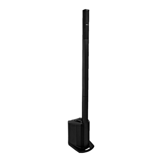
• Carry it in one trip – The entire system is light enough to be carried in a single trip. • Set it up in one minute – The interlocking components of the L1 Compact system allow system setup in less than a minute. There are no external speaker wires required. An integrated bass enclosure with an intuitive user interface eliminates the need for separate components. - Page 7 ® you quickly identify the position that can work best for you. Collapsed position Extended position The L1 Compact Extensions are not re- Loudspeaker quired when using the L1 Compact Portable Array Line Array System in the collapsed position. They are included for situations where you...
- Page 8 Product Description Connections and controls The power stand control panel provides all the necessary connectors, controls, and indicators for operation. Channel 1 Channel 2 (Microphone input) (Utility channel – multiple input) The channel 1 input is for use only with a 6.
-
Page 9: Packaging Part List, L1 Compact Power Stand (Includes Array) (See Figure 1)
Packaging Part List L1 Compact Power Stand (includes Array) (see Figure 1) ® Item Description Bose Part Vendor Part Note Number Number Number Inner Sheet, Cardboard 324116-001S 1451-0340+0 Power Cord, 120V, (US) 298165 7012-7340+0 Power Cord, 220V (China) 318882-210S 7013-0580+0... -
Page 10: Packaging Part List, L1 Compact Array Extensions (See Figure 2)
L1 Compact Array Extensions (see Figure 2) ® Item Description Bose Part Vendor Part Note Number Number Number Carton, Extensions 317385-000S 1481-4701+0 Extensions Carry Bag 317404-010S 4201-1170+0 L1 Compact Extension 318881-010S svc-cajun11+exte Figure 2. L1 Compact Array Extensions Packaging View... -
Page 11: Main Part List, L1 Compact Power Stand (See Figure 3)
Main Part List L1 Compact Power Stand (see Figure 3) ® Item Description Bose Part Vendor Part Number Note Number Number Grille, Power Stand, Left 317363-010S 4135+8921+0 Grille, Power Stand, Right 317364-010S 4135-8931+0 Guide, Array, ABS, Blk 4155-3811+0 Woofer, 8 inch... - Page 12 Main Part List L1 Compact Power Stand, continued (see Figure 3) ® Item Description Bose Part Vendor Part Number Note Number Number PCB Assy, COB COM 317371-000S SVC-CAJUN01+COB (Includes: PRE-AMP ASSY/3.5MM Jack Input Card/Line Output Card) PCB Assy, IN COM...
-
Page 13: Main Part List, L1 Compact Array Speaker (See Figure 4)
3, 4 L=250/180, RD/BLK Array Logo 317407-010S 2150-7311+0 EVA Gasket, Baffle 4149-1121+0 Screw, M3x13, 5.6MM, BK-ZN/CR HD 2931-3013+3000 Label, Serial Number, 30x7mm Guide Strip, Array 317366-010S 4155-3861+0 Screw, M3x12, CSH, BK 2901-3012+3000 Figure 4. L1 Compact Array Speaker Exploded View... -
Page 14: Main Part List, L1 Compact Array Extension Exploded View (See Figure 5)
Main Part List L1 Compact Array Extension Exploded View (see Figure 5) ® Item Description Bose Part Vendor Part Number Note Number Number Array Extension, Complete Assembly, 318881-010S svc-cajun11+exte Consists of below items Wire, 2P, #20, UL2468, L=850 7013-0750+0 3, 4... -
Page 15: Electrical Part List
Electrical Part List Input/Output PCB Assembly Resistors Reference Description Vendor Part Number Note Designator R100 100 OHM, RMG, 1/16W, 1%, 0603 4723-101A+P R101 100 OHM, RMG, 1/16W, 1%, 0603 4723-101A+P R102 2K, RMG, 1/16W, 1%, 0603/1608 4723-202A+P R103 2K, RMG, 1/16W, 1%, 0603/1608 4723-202A+P R104 4.99K, RMG, 1/16W, 1%, 0603... -
Page 16: Input/Output Pcb Assembly
Electrical Part List Input/Output PCB Assembly Resistors (continued) Reference Description Vendor Part Number Note Designator R148 10K, RMG, 1/16W, 1%, 0603 4723-103A+P-R R149 270 OHM, RMG, 1/16W, 1%, 0603 4723-271A+P-R R150 270 OHM, RMG, 1/16W, 1%, 0603 4723-271A+P-R R151 34.8K, RMG, 1/10W, 1%, 0603 4720-3482+P R152 68K, RMG, 1/16W, 1%, 0603... - Page 17 Electrical Part List Input/Output PCB Assembly Resistors (continued) Reference Description Vendor Part Number Note Designator R209 12K, RMG, 1/16W, 1%, 0603 4723-123A+P R210 150 OHM, RMG, 1/16W, 1%, 0603 4723-154A+P-R R211 75K, RMG, 1/16W, 1%, 0603 4723-753A+P R213 1K, RMG, 1/16W, 1%, 0603/1608 4723-102A+P R214 1K, RMG, 1/16W, 1%, 0603/1608...
- Page 18 Electrical Part List Input/Output PCB Assembly Resistors (continued) Reference Description Vendor Part Number Note Designator R272 510 OHM, RMG, 1/4W, 5%, 1206 4725-511J+6 R275 100K, RMG, 1/16W, 1%, 0603 4723-104A+P-R R276 15.8K, RMG, 1/10W, 1%, 0603 4720-1582+P R277 470K, RMG, 1/16W, 1%, 0603 4723-474A+P R278 0 OHM, RMG, 1/16W, 5%, 0603...
- Page 19 Electrical Part List Input/Output PCB Assembly Resistors (continued) Reference Description Vendor Part Number Note Designator R340 10K, RMG, 1/16W, 1%, 0603 4723-103A+P-R R341 158K, RMG, 1/10W, 1%, 0603 4720-1583+P R342 23.2K, RMG, 1/16W, 1%, 0603/1608 4723-2322+P R343 24.3K, RMG, 1/10W, 1%, 0603 4720-2432+P R344 24.3K, RMG, 1/10W, 1%, 0603...
- Page 20 Electrical Part List Input/Output PCB Assembly Resistors (continued) Reference Description Vendor Part Number Note Designator R413 24.3K, RMG, 1/10W, 1%, 0603 4720-2432+P R414 24.3K, RMG, 1/10W, 1%, 0603 4720-2432+P R424 20K, RMG, 1/16W, 1%, 0603/1608 4723-203A+P R425 1M, RMG, 1/16W, 1%, 0603 4723-105A+P R426 510 OHM, RMG, 1/4W, 5%, 1206...
- Page 21 Electrical Part List Input/Output PCB Assembly Capacitors Reference Description Vendor Part Number Note Designator C100 0.1uF, CC, 50V, 5%, 0603 150F-104J+P-AC C101 0.01uF, CC, 50V, 5%, 0603 150F-103J+P-AC C102 100pF, CC, 50V, 5%, 0603/1608, 1X2 150F-101J+P-AC C103 100pF, CC, 50V, 5%, 0603/1608, 1X2 150F-101J+P-AC C105 22uF, CE, 16V, 20%, RLT, 4X7, RC2...
- Page 22 Electrical Part List Input/Output PCB Assembly Capacitors (continued) Reference Description Vendor Part Number Note Designator C148 0.1uF, CC, 50V, 5%, 0603 150F-104J+P-AC C149 10pF, CC, 50V, 5%, 0603 150F-100J+P-AC C151 10uF, CE, 16V, 20%, RLT, 4X7, ELNA 157D-106M+K-GME C152 100pF, CC, 50V, 5%, 0603/1608, 1X2 150F-101J+P-AC C153 1000pF, CC, 50V, 5%, 0603, X7R...
- Page 23 Electrical Part List Input/Output PCB Assembly Capacitors (continued) Reference Description Vendor Part Number Note Designator C240 10uF, CE, 16V, 20%, RLT, 4X7, ELNA 157D-106M+K-GME C242 0.1uF, CC, 50V, 5%, 0603 150F-104J+P-AC C243 10uF, CE, 16V, 20%, RLT, 4X7, ELNA 157D-106M+K-GME C244 10uF, CE, 16V, 20%, RLT, 4X7, ELNA 157D-106M+K-GME...
- Page 24 Electrical Part List Input/Output PCB Assembly Capacitors (continued) Reference Description Vendor Part Number Note Designator C337 0.1F, CC, 25V, 10%, 0603, X7R 150E-104K+P-AC C338 0.1F, CC, 25V, 10%, 0603, X7R 150E-104K+P-AC C339 0.047uF, CC, 50V, 5%, 0603, 0.8X1.6 150F-473J+P-AC C340 0.1uF, CC, 50V, 5%, 0603 150F-104J+P-AC C341...
- Page 25 Electrical Part List Input/Output PCB Assembly Capacitors (continued) Reference Description Vendor Part Number Note Designator C407 0.1uF, CC, 50V, 5%, 0603 150F-104J+P-AC C408 0.1uF, CC, 50V, 5%, 0603 150F-104J+P-AC C409 1000pF, CC, 50V, 5%, 0603, X7R 150F-102J+P-AC C410 1000pF, CC, 50V, 5%, 0603, X7R 150F-102J+P-AC C411 100pF, CC, 50V, 5%, 0603/1608, 1X2...
- Page 26 Electrical Part List Input/Output PCB Assembly Capacitors (continued) Reference Description Vendor Part Number Note Designator C515 0.1uF, CC, 50V, 5%, 0603 150F-104J+P-AC C518 0.1uF, CC, 50V, 5%, 0603 150F-104J+P-AC C519 0.1uF, CC, 50V, 5%, 0603 150F-104J+P-AC C520 47uF, CE, 16V, 20%, RLT, 5X7 157D-476M+K-IME C521 47uF, CE, 16V, 20%, RLT, 5X7...
- Page 27 Electrical Part List Input/Output PCB Assembly Diodes (continued) Reference Description Vendor Part Number Note Designator D304 DIODE, BAV99, SOT23, PHILIPS 4840-8970+3 D305 DIODE, BAV99, SOT23, PHILIPS 4840-8970+3 D306 DIODE, BAV99, SOT23, PHILIPS 4840-8970+3 D401 DIODE, BAV99, SOT23, PHILIPS 4840-8970+3 D402 DIODE, BAV99, SOT23, PHILIPS 4840-8970+3 D500...
- Page 28 Electrical Part List Input/Output PCB Assembly Integrated Circuits Reference Description Vendor Part Number Note Designator U100 NJM2068M-#ZZZB, DUAL OP AMP 3130-6890+0 U101 TL072CDR, DUAL J-FET INPUT, OP-AMP 3130-8020+0 U102 TL072CDR, DUAL J-FET INPUT, OP-AMP 3130-8020+0 U103 TL072CDR, DUAL J-FET INPUT, OP-AMP 3130-8020+0 U104 TL072CDR, DUAL J-FET INPUT, OP-AMP...
-
Page 29: 3.5Mm Line Input Pcb Assembly
Electrical Part List Input/Output PCB Assembly Miscellaneous Reference Description Vendor Part Number Note Designator CN300A WAFER, 10 PIN, P2 2102-100S+003 CN302A WIRE-CONN, 10P, P2.0, #26, UL2468, L=110, 7012-7033+0 CN308A CONNECTOR, 5 PIN, P2.5 (JST 05JQ-BT) 2101-1371+0 J100 XLR, FEMALE CONN, NC3FAV1-0 2113-1337+1 J200 JACK, RCA, 2P, UPRIGHT, W/R, SILVER... - Page 30 Electrical Part List Output PCB Assembly Capacitors Reference Description Vendor Part Number Note Designator C351 1000pF, CC, 50V, 5%, 0603, X7R 150F-102J+P-AC C361 100pF, CC, 50V, 5%, 0603/1608, 1X2 150F-101J+P-AC C362 100pF, CC, 50V, 5%, 0603/1608, 1X2 150F-101J+P-AC C447 1000pF, CC, 50V, 5%, 0603, X7R 150F-102J+P-AC C449 100pF, CC, 50V, 5%, 0603/1608, 1X2...
-
Page 31: Power Amplifier Pcb Assembly
Electrical Part List Power Amplifier PCB Assembly Resistors Reference Description Vendor Part Note Designator Number 110K, RMG, 1/4W, 5%, 1206 4725-114J+6 10 OHM, RMG, 1/8W, 1%, 1206 4721-100A+6 49.9 OHM, RMG, 1/4W, 1%, 1206 4725-49R9+6 20 OHM, RMG, 1/4W, 1%, 1206 4725-200A+6 1M, RMG, 1/16W, 1%, 0603 4723-105A+P... - Page 32 Electrical Part List Power Amplifier PCB Assembly Resistors (continued) Reference Description Vendor Part Note Designator Number 20K, RMG, 1/16W, 1%, 0603/1608 4723-203A+P 5.6K, RMG, 1/16W, 1%, 0603/1608 4723-562A+P 39K, RMG, 1/16W, 5%, 0603 4723-393J+P-R 100K, RMG, 1/16W, 1%, 0603 4723-104A+P-R 5.6K, RMG, 1/16W, 1%, 0603/1608 4723-562A+P 39K, RMG, 1/10W, 1%, 0603...
- Page 33 Electrical Part List Power Amplifier PCB Assembly Capacitors (continued) Reference Description Vendor Part Note Designator Number 1000uF, CE, 35V, 20%, RLT, 12.5X25, 105C, 157Q-108M+K- LOW ESR X&TR 0.01uF, CC, 50V, 5%, 0603 150F-103J+P-AC 1000pF, CC, 1000V, 10%, RLT, 6X3, 125C, X7R 1511-102K+K-0N 1000pF, CC, 1000V, 10%, RLT, 6X3, 125C, X7R 1511-102K+K-0N...
- Page 34 Electrical Part List Power Amplifier PCB Assembly Capacitors (continued) Reference Description Vendor Part Note Designator Number 0.1uF, CC, 100V, 10%, 1206, AVX 150H-104K+6-CFD 0.01uF, CC, 50V, 5%, 0603 150F-103J+P-AC 0.01uF, CC, 50V, 5%, 0603 150F-103J+P-AC 0.01uF, CC, 50V, 5%, 0603 150F-103J+P-AC 0.01uF, CC, 50V, 5%, 0603 150F-103J+P-AC...
- Page 35 Electrical Part List Power Amplifier PCB Assembly Capacitors (continued) Reference Description Vendor Part Note Designator Number XYC1 680pF, CC, 400V, 10%, RL, 10X8 150T-681K+5-SO XYC3 680pF, CC, 400V, 10%, RL, 10X8 150T-681K+5-SO XYC5 1000pF, CC, 400V, 20%, RL, Y5, U, 9.5X8, 150T-102M+5-RO AH09E102MLO 1000pF, CC, 400V, 20%, RL, Y5, U, 9.5X8,...
- Page 36 Electrical Part List Power Amplifier PCB Assembly Diodes Reference Description Vendor Part Note Designator Number DIODE BRIDGE, 800V, 8A, GBU8K, RL 4840-9218+5 3, 4 BAV21W, 200V, 0.2A, SOD-123, SMD 480V-21W0+3 RECTIFIER, UF4006-T GI, AT 4840-8530+2 MUR1640, ULTRA, 400V, 16A, TO-220AB 4801-6400+9 MUR1640, ULTRA, 400V, 16A, TO-220AB 4801-6400+9...
- Page 37 Electrical Part List Power Amplifier PCB Assembly Miscellaneous Reference Description Vendor Part Note Designator Number HEATSINK, AMP, 160X120, AL PLATE 5401-0191+0 WAFER, 3 PIN, P=3.96 2101-3065+0 CONNECTOR, 2P, P3.96, STRAIGHT, M 2101-2780+0 WAFER, 10 PIN, P2 2102-100S+003 0.33uF, CM, 300V, 10%, RB, P15, 18X15.5X10 1511-334K+9-03Z 3, 4 0.33uF, CM, 300V, 10%, RB, P15, 18X15.5X10...
-
Page 38: Disassembly Procedures
Disassembly Procedures L1 Compact Power Stand Procedures CAUTION: The SMD integrated circuits used on the Input / Output PCB are extremely sensitive to ESD damage. Be sure to use an approved and tested ESD strap that is properly grounded to your work bench before attempting disassembly or repair of the L1 Compact Power Stand. - Page 39 Disassembly Procedures 2. Input / Output PCB Removal CAUTION: The SMD integrated circuits used on the Input / Output PCB are extremely sensitive to ESD damage. Be sure to use an approved and tested ESD strap that is properly grounded to your work bench before attempting disassembly or repair of the L1 Compact Power Stand.
- Page 40 Disassembly Procedures Input/Output PCB Re-assembly Note: Be sure that the LED lightpipes are properly aligned with the holes in the PCB and the openings in the top cover when re-installing the I/O PCB assembly. 4. Line Output Card Removal 4.1 Perform procedure 1. 4.2 Remove the one screw at the RCA jacks and the plastic nut at the 1/4”...
- Page 41 Disassembly Procedures 5.2 Remove the four screws that secure the power amplifier / SMPS PCB assembly to the power stand’s mounting bracket. 5.3 Carefully slide the power amplfier / SMPS PCB downward until the top of the board clears the upper part of the bracket. 5.4 Slide the PCB assembly out through the access panel opening and disconnect the four wire harnesses.
- Page 42 Disassembly Procedures 6. AC Inlet and Power Switch Removal 6.1 Perform procedure 5. 6.2 Disconnect the three wires that connect to the AC inlet jack. Remove the two screws that secure the AC inlet to to the cabinet. Lift out the jack. 6.3 Disconnect the two wires that connect to the AC power switch.
- Page 43 Re-assembly Note: Be sure to align the woofer grilles to the slots in the top cover and the plastic foot when replacing the foot. L1 Compact Array Procedures 1. Grille Removal 1.1 Grasp the grille and carefully pull it away from the array.
- Page 44 Disassembly Procedures 2. Driver Removal 2.1 Perform procedure 1. 2.2 Remove the four screws that secure the driver to the baffle. Lift out the driver. 2.3 Cut the wires as close to the driver terminals as possible. Re-assembly Note: Be sure to observe polarity when re-connecting the driver wires.
-
Page 45: Test Procedures
Test Procedures ® Compact Power Stand Tests 2. Channel 2 LED/Gain Test 2.1 Set the channel 2 ToneMatch switch to CAUTION: The SMD integrated circuits used the OFF position (down). on the Input / Output PCB are extremely sensitive to ESD damage. Be sure to use an 2.2 Using an balanced TRS cable, apply a approved and tested ESD strap that is balanced, 1kHz, -50dBV (3.16mVrms) sine... - Page 46 Test Procedures 3.6 Measure the output level at the 5. Channel 2 ToneMatch Not Active EQ 1/4” balanced line output jack. It should be Check 0dBV +/- 1dBV (1Vrms). 5.1 Set the channel 2 volume control to the 3.7 Measure the output level at the unbal- 12 o’clock position.
- Page 47 Test Procedures Note: The following tests will check the 8.5 Connect a 4 Ohm, 50 Watt load resistor performance of the Power Supply / Amplifier to pins 1 and 2 of the bass amplifier output PCB assembly connector CN2. These connectors are located near the bottom of the PCB assem- bly.
- Page 48 Suspen- sion noise will not be heard with program material. L1 Compact Line Array Tests Set up the unit under test as shown below. 3. Transducer Phase Test 3.1 Momentarily apply a DC voltage of 5V,...
-
Page 49: Ic Diagrams
IC Diagrams Y Package (TO-220-7C) CONTROL (C) DRAIN (D) INTERNAL SUPPLY Note: Y package for TOP254-258 SHUNT REGULATOR/ ERROR AMPLIFIER SOFT START 5.8 V 4.8 V 5.8 V INTERNAL UV PS(UPPER) COMPARATOR V I (LIMIT) CURRENT LIMIT ADJUST ÷ 16 PS(LOWER) ON/OFF SHUTDOWN/... - Page 50 IC Diagrams DDA2 DDA1 STABI PROT DDP2 DDP1 SSA2 3 (20) 10 (4) 13 (7) 23 (16) 15 (9) SGND2 DDP2 BOOT1 9 (3) RELEASE1 IN1M DRIVER DDA2 INPUT HIGH SWITCH1 CONTROL 8 (2) STAGE MODULATOR 16 (10) IN1P OUT1 ENABLE1 HANDSHAKE DRIVER...
-
Page 51: Service Manual Revision History
Service Manual Revision History Date Revision Description of Change Change Driven Pages Level Affected 5/09 Document released at revision 00. Service manual release 5/09 Added power stand packing sheet. Vendor change... - Page 52 SPECIFICATIONS AND FEATURES SUBJECT TO CHANGE WITHOUT NOTICE Bose Corporation The Mountain Framingham Massachusetts USA 01701 P/N: 318882-SM Rev. 01 5/2009 (P) http://serviceops.bose.com...