Table of Contents
Advertisement
TECHNICAL DATA & SERVICE MANUAL
R32
Middle Static Pressure Duct
R32 Models
Model No.
Indoor Units
Indoor
Type
Units Type
U3
4-Way Cassette
Middle Static
F3
Pressure Duct
Outdoor Units
Type
Outdoor Units Type
PZ3
Single Split (1-phase)
Indoor Unit
4-Way Cassette
36
50
S-3650PU3E
S-3650PF3E
36
50
U-36PZ3E5
U-50PZ3E5
60
71
S-6071PU3E
S-6071PF3E
60
71
U-60PZ3E5
U-71PZ3E5
Order No. SBPAC1908013CE
Outdoor Unit
SM830283-00
REFERENCE NO.
Advertisement
Chapters
Table of Contents

Related Manuals for Panasonic S-3650PU3E


Summary of Contents for Panasonic S-3650PU3E
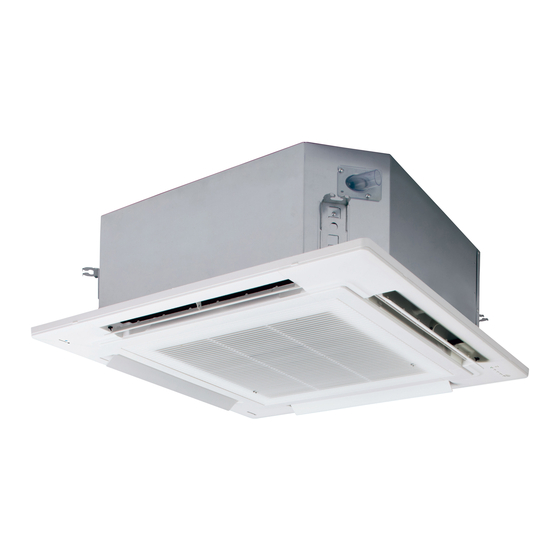
- Page 1 Indoor Unit Outdoor Unit Middle Static Pressure Duct 4-Way Cassette R32 Models Model No. Indoor Units Indoor Type Units Type 4-Way Cassette S-3650PU3E S-6071PU3E Middle Static S-3650PF3E S-6071PF3E Pressure Duct Outdoor Units Type Outdoor Units Type Single Split (1-phase) U-36PZ3E5...
- Page 2 IMPORTANT! For appliances connected via an Please Read Before Starting air duct system to one or more rooms, only auxiliary devices This air conditioner must be installed by the sales dealer approved by the appliance or installer. manufacturer or declared suitable This information is provided for use only by authorized persons.
- Page 3 (Type F3) • Check that cabling will not be subject to wear, corrosion, excessive pressure, • Ducts connected to an appliance shall not contain a potential ignition source; vibration, sharp edges or any other adverse environmental effects. • For appliances connected via an air duct The check shall also take into account system to one or more rooms, the supply the effects of aging or continual vibration...
- Page 4 • Ensure that the detector is not a WARNING potential source of ignition and is suitable for the refrigerant used. • When performing piping work, do not mix air except for specified • Leak detection equipment shall be set refrigerant (R32) in refrigeration at a percentage of the lower flammable cycle.
- Page 5 Others WARNING When disposal of the product, do follow • This product must not be the precautions in “11. Recovery” on modified or disassembled under page 1-11-2-1-6 and comply with national any circumstances. Modified or regulations. disassembled unit may cause fire, electric shock or injury. WARNING • Do not clean inside the indoor and outdoor units by users. Engage • Do not sit or step on the authorized dealer or specialist for unit.
- Page 6 SERVICING CAUTION • Any qualified person who is involved with working on or breaking into a refrigerant circuit should hold a current valid certificate from an industry-accredited assessment authority, which authorizes their competence to handle refrigerants safely in accordance with an industry recognised assessment specification. •...
- Page 7 Marking to the equipment continues to be visible and legible. Markings and signs • that are illegible shall be corrected. Refrigerating pipe or components are installed in a position where they are • unlikely to be exposed to any substance which may corrode refrigerant containing components, unless the components are constructed of materials which are inherently resistant to being corroded or are suitably protected against being so corroded.
- Page 8 REMOVAL AND EVACUATION CAUTION • When breaking into the refrigerant circuit to make repairs – or for any other purpose – conventional procedures shall be used. However, it is important that best practice is followed since flammability is a consideration. The following procedure shall be adhered to: Remove refrigerant.
- Page 9 Recovery equipment and cylinders conform to the appropriate standards. • d) Pump down refrigerant system, if possible. e) If a vacuum is not possible, make a manifold so that refrigerant can be removed from various parts of the system. f) Make sure that cylinder is situated on the scales before recovery takes place. g) Start the recovery machine and operate in accordance with instructions.
- Page 10 Check of Density Limit 1. Outdoor The refrigerant (R32), which is used in the air conditioner, is a fl ammable refrigerant. So the requirements for installation space of appliance are determined according to the refrigerant charge amount (m ) used in the appliance. The minimum indoor fl...
- Page 11 2. Indoor 2-1. Type U3 The refrigerant (R32), which is used in the air conditioner, is a flammable refrigerant. So the requirements for installation space of appliance are determined according to the refrigerant charge amount [m ] used in the appliance. Regarding the refrigerant charge amount [m ] used in the appliance, refer to the installation instructions for the outdoor unit.
- Page 12 2-2. Type F3 The refrigerant (R32), which is used in the air conditioner, is a flammable refrigerant. So the requirements for installation space of appliance are determined according to the refrigerant charge amount [m ] used in the appliance. Regarding the refrigerant charge amount [m ] used in the appliance, refer to the installation instructions for the outdoor unit.
- Page 13 Table 2 [Amin] m ] kg Line 1 Line 2 Line 3 1.22 12.8 14.5 16.8 19.3 22.0 24.8 27.8 ≤ 1.22 : Can be installed ≤ m 1.22 < m : Can be installed above “Density Limit Line” *1 *1 See Table 1-2 and Fig.
- Page 14 Precautions for Installation Using New Refrigerant 1. Care regarding tubing 1-1. Process tubing Material: Use seamless phosphorous deoxidized copper tube for refrigeration. Wall thickness shall comply with the applicable legislation. The minimal wall thickness must be in accordance with the table below. Tubing size: Be sure to use the sizes indicated in the table below.
- Page 15 Important Information Regarding The Refrigerant Used This product contains fluorinated greenhouse gases. Do not vent gases into the atmosphere. Refrigerant type: R32 value: 675 GWP = global warming potential Periodical inspections for refrigerant leaks may be required depending on European or local legislation. Please contact your local dealer for more information.
- Page 16 Combination of Indoor and Outdoor Units Single-phase S-6071PU3E S-6071PU3E S-3650PU3E S-3650PU3E (S-3650PU3E(36)) (S-3650PU3E(50)) (S-6071PU3E(60)) (S-6071PU3E(71)) U-60PZ3E5 U-71PZ3E5 U-36PZ3E5 U-50PZ3E5 S-6071PF3E S-3650PF3E S-3650PF3E S-6071PF3E (S-3650PF3E(36)) (S-6071PF3E(60)) (S-6071PF3E(71)) (S-3650PF3E(50)) U-71PZ3E5 U-36PZ3E5 U-50PZ3E5 U-60PZ3E5...
-
Page 17: Table Of Contents
—— CONTENTS —— Section 1. SPECIFICATIONS ....................1-i 1-1. Unit Specifications ......................1-1-1-1-1 Dimensional Data ......................1-2-1-1-1 3. Refrigerant Flow Diagram .....................1-3-1 4. Operating Range ........................1-4-1 5. Capacity Correction Graph According to Temperature Condition ..........1-5-1 6. Noise Criterion Curves ....................1-6-1-1-1 7. Indoor Fan Performance ......................1-7-1 8. - Page 18 Section 4. CONTROL FUNCTIONS ..................4-i 4-1. Room Temperature Control ...................... 2. Heating Standby ........................4-3. Automatic Fan Speed Control ....................4. Drain Pump Control ......................... 4-5. Automatic Heating/Cooling Control ..................6. Automatic Flap Control ......................4-7. Filter Sign ..........................4-8.
- Page 19 Section 8. HOW TO INSTALL THE WIRELESS (INFRARED) REMOTE CONTROLLER RECEIVER .. 8-i ..................... 8-1 8-1. Important Safety Instructions 8-2. Optional Controller (Remote Controller) ................8-2-1-1 ..................8-2-1-1 8-2-1-1. Names and Operations ....................8-2-1-3 8-2-1-2. Installing Batteries ..................8-2-1-3 8-2-1-3. Setting the Current Time ......................
- Page 20 – MEMO –...
-
Page 21: Unit Specifications
1. SPECIFICATIONS 1-1. Unit Specifications .................... 1-1-1-1-1 1. 4-Way Cassette Type (U3) ......................1-1-1-1-1 2. Middle Static Pressure Duct Type (F3) ..................1-1-1-2-1 1-2. Dimensional Data ....................1-2-1-1-1 (A) Indoor Units ..........................1-2-1-1-1 (B) Outdoor Units ..........................1-2-2-1-1 1-3. Refrigerant Flow Diagram ..................1-3-1 1-4. - Page 22 Single - Type 1-1. Unit Specifications 1. 4-Way Cassette Type S-3650PU3E(36) / U-36PZ3E5 INDOOR MODEL S-3650PU3E(36) PANEL MODEL Standard type : CZ-KPU3 or CZ-KPU3W / ECONAVI type : CZ-KPU3A or CZ-KPU3AW OUTDOOR MODEL U-36PZ3E5 Branch pipe MODEL Performance test condition ISO5151 / EN14511 / EN12102 / EN14825 Ø, Hz...
- Page 23 Single - Type 1-1. Unit Specifications 1. 4-Way Cassette Type S-3650PU3E(50) / U-50PZ3E5 INDOOR MODEL S-3650PU3E(50) PANEL MODEL Standard type : CZ-KPU3 or CZ-KPU3W / ECONAVI type : CZ-KPU3A or CZ-KPU3AW OUTDOOR MODEL U-50PZ3E5 Branch pipe MODEL Performance test condition ISO5151 / EN14511 / EN12102 / EN14825 Ø, Hz...
- Page 24 Single - Type 1-1. Unit Specifications 1. 4-Way Cassette Type S-6071PU3E(60) / U-60PZ3E5 INDOOR MODEL S-6071PU3E(60) PANEL MODEL Standard type : CZ-KPU3 or CZ-KPU3W / ECONAVI type : CZ-KPU3A or CZ-KPU3AW OUTDOOR MODEL U-60PZ3E5 Branch pipe MODEL Performance test condition ISO5151 / EN14511 / EN12102 / EN14825 Ø, Hz 1Ø...
- Page 25 Single - Type 1-1. Unit Specifications 1. 4-Way Cassette Type S-6071PU3E(71) / U-71PZ3E5 INDOOR MODEL S-6071PU3E(71) PANEL MODEL Standard type : CZ-KPU3 or CZ-KPU3W / ECONAVI type : CZ-KPU3A or CZ-KPU3AW OUTDOOR MODEL U-71PZ3E5 Branch pipe MODEL Performance test condition ISO5151 / EN14511 / EN12102 / EN14825 Ø, Hz 1Ø...
- Page 26 Single - Type 1-1. Unit Specifications 2. Middle Static Pressure Duct Type S-3650PF3E(36) / U-36PZ3E5 INDOOR MODEL S-3650PF3E(36) PANEL MODEL OUTDOOR MODEL U-36PZ3E5 Branch pipe MODEL Performance test condition ISO5151 / EN14511 / EN12102 / EN14825 Ø, Hz 1Ø 50Hz 1Ø...
- Page 27 Single - Type 1-1. Unit Specifications 2. Middle Static Pressure Duct Type S-3650PF3E(50) / U-50PZ3E5 INDOOR MODEL S-3650PF3E(50) PANEL MODEL OUTDOOR MODEL U-50PZ3E5 Branch pipe MODEL Performance test condition ISO5151 / EN14511 / EN12102 / EN14825 Ø, Hz 1Ø 50Hz 1Ø...
- Page 28 Single - Type 1-1. Unit Specifications 2. Middle Static Pressure Duct Type S-6071PF3E(60) / U-60PZ3E5 INDOOR MODEL S-6071PF3E(60) PANEL MODEL OUTDOOR MODEL U-60PZ3E5 Branch pipe MODEL Performance test condition ISO5151 / EN14511 / EN12102 / EN14825 Ø, Hz 1Ø 50Hz 1Ø...
- Page 29 Single - Type 1-1. Unit Specifications 2. Middle Static Pressure Duct Type S-6071PF3E(71) / U-71PZ3E5 INDOOR MODEL S-6071PF3E(71) PANEL MODEL OUTDOOR MODEL U-71PZ3E5 Branch pipe MODEL Performance test condition ISO5151 / EN14511 / EN12102 / EN14825 Ø, Hz 1Ø 50Hz 1Ø...
- Page 30 Detailed view Y cannot be installed. Air intake Discharge outlet Refrigerant tubing joint (liquid tube) S-3650PU3E : ø6.35 (flared) S-6071PU3E : ø9.52 (flared) *1 Refrigerant tubing joint (gas tube) 4 - M4 S-3650PU3E : ø12.7 (flared) Tapping screw holes S-6071PU3E(60) : ø15.88 (flared) *2...
- Page 31 1-2. Dimensional Data (A) Indoor Units: S-3650PF3E, S-6071PF3E Unit: mm Type 3650 450 (Pitch 150 × 3) 6071 1,067 1,000 750 (Pitch 150 × 5) Unit: mm 80.6 8-ø3.2 hole For M4 self-tapping screw A (Suspension bolt ptich) (200) 33.5 33.5 D (Flange O.D.) Refrigerant tubing joint (liquid tube)
- Page 32 1-2. Dimensional Data (B) Outdoor Units: U-36PZ3E5, U-50PZ3E5 Mounting Hole (4-R6.5), anchor bolt:M10 Refrigerant tubing(liquid tube), flared connection ( Ø 6.35) Refrigerant tubing(gas tube), flared connection( Ø 12.7) Air Intake 68.7 62.6 394.3 Drain hole Ø Air Discharge 32.2 327.1 357.1 1-2-2-1-1...
- Page 33 1-2. Dimensional Data (B) Outdoor Units: U-60PZ3E5, U-71PZ3E5 Mounting hole (4-R6.5), anchor bolt : M10 Refrigerant tubing (liquid tube), flared connection (Ø 6.35) Refrigerant tubing (gas tube), flared connection U-60PZ3E5 ( Ø 12.7) U-71PZ3E5 ( Ø 15.88) Air Intake 34.7 65.4 Drain hole Ø...
- Page 34 1-3. Refrigerant Flow Diagram Outdoor Units: U-36PZ3E5 S-3650PU3E (36) S-3650PF3E (36) Ø6.35 Ø6.35 Ø6.35 Distributor Heat exchanger Ø12.7 Ø12.7 Ø12.7 1-3-1...
- Page 35 1-3. Refrigerant Flow Diagram Outdoor Unit: U-50PZ3E5 S-3650PU3E (50) S-3650PF3E (50) Ø6.35 Ø6.35 Ø6.35 Distributor Heat exchanger Ø12.7 Ø12.7 Ø12.7 1-3-2...
- Page 36 1-3. Refrigerant Flow Diagram Outdoor Unit: U-60PZ3E5 S-6071PU3E (60) S-6071PF3E (60) Liquid socket tube (Ø9.52-Ø6.35) Ø6.35 Ø9.52 Ø6.35 Distributor Heat exchanger Ø12.7 Ø15.88 Ø12.7 Gas socket tube (Ø15.88-Ø12.7) 1-3-3...
- Page 37 1-3. Refrigerant Flow Diagram Outdoor Unit: U-71PZ3E5 S-6071PU3E (71) S-6071PF3E (71) Liquid socket tube (Ø9.52-Ø6.35) Ø6.35 Ø9.52 Ø6.35 Distributor Heat exchanger Ø15.88 Ø15.88 Ø15.88 1-3-4...
-
Page 38: Operating Range
1-4. Operating Range Type PZ3 Temperature Indoor air intake temp. Outdoor air intake temp. Maximum 32°C DB / 25°C WB 43°C DB Cooling Minimum 18°C DB / 14°C WB -10°C DB Maximum 30°C DB / − WB 24°C DB/18°C WB Heating Minimum 16°C DB / −... -
Page 39: Capacity Correction Graph According To Temperature Condition
1-5. Capacity Correction Graph According to Temperature Condition U-36PZ3E5 (For 50 Hz) Cooling capacity ratio (maximum capacity) Heating capacity ratio (maximum capacity) Indoor air intake temp (°C WB) Indoor air intake temp (°C DB) 24°C 20°C 16°C 22℃ 19℃ 16℃ Indoor air intake temp (°C WB) Indoor air intake temp (°C DB) 22°C... - Page 40 1-5. Capacity Correction Graph According to Temperature Condition U-50PZ3E5 (For 50 Hz) Cooling capacity ratio (maximum capacity) Heating capacity ratio (maximum capacity) Indoor air intake temp (°C WB) Indoor air intake temp (°C DB) 24°C 20°C 16°C 22℃ 19℃ 16℃ Indoor air intake temp (°C WB) Indoor air intake temp (°C DB) 22°C...
- Page 41 1-5. Capacity Correction Graph According to Temperature Condition U-60PZ3E5 (For 50 Hz) Cooling capacity ratio (maximum capacity) Heating capacity ratio (maximum capacity) Indoor air intake temp (°C WB) Indoor air intake temp (°C DB) 24°C 20°C 16°C 22℃ 19℃ 16℃ Indoor air intake temp (°C WB) Indoor air intake temp (°C DB) 22°C...
- Page 42 1-5. Capacity Correction Graph According to Temperature Condition U-71PZ3E5 (For 50 Hz) Cooling capacity ratio (maximum capacity) Heating capacity ratio (maximum capacity) Indoor air intake temp (°C WB) Indoor air intake temp (°C DB) 24°C 20°C 16°C 22℃ 19℃ 16℃ Indoor air intake temp (°C WB) Indoor air intake temp (°C DB) 22°C...
- Page 43 U-36PZ3E5 Type U3 Rated capacity ratio for heating Rated capacity ratio for cooling 149% 127% Capacity (kW) Capacity (kW) Type F3 Rated capacity ratio for heating Rated capacity ratio for cooling 160% 127% Capacity (kW) Capacity (kW) NOTE 1. Each type of the characteristics shows the value under the following conditions. Equivalent tubing length : 5m Difference of elevation...
- Page 44 U-50PZ3E5 Type U3 Rated capacity ratio for cooling Rated capacity ratio for heating 170% 137% Capacity (kW) Capacity (kW) Type F3 Rated capacity ratio for cooling Rated capacity ratio for heating 140% 107% Capacity (kW) Capacity (kW) NOTE 1. Each type of the characteristics shows the value under the following conditions. Equivalent tubing length : 5m Difference of elevation...
- Page 45 U-60PZ3E5 Type U3 Rated capacity ratio for cooling Rated capacity ratio for heating 147% 164% Capacity (kW) Capacity (kW) Type F3 Rated capacity ratio for cooling Rated capacity ratio for heating 176% 149% Capacity (kW) Capacity (kW) NOTE 1. Each type of the characteristics shows the value under the following conditions. Equivalent tubing length : 5m Difference of elevation...
- Page 46 U-71PZ3E5 Type U3 Rated capacity ratio for cooling Rated capacity ratio for heating 143% 128% 10.0 10.0 Capacity (kW) Capacity (kW) Type F3 Rated capacity ratio for cooling Rated capacity ratio for heating 157% 134% 10.0 10.0 Capacity (kW) Capacity (kW) NOTE 1.
-
Page 47: Noise Criterion Curves
4000 8000 Frequency at center of sound pressure band (Hz) Frequency at center of sound pressure band (Hz) * For S-3650PU3E (36) and S-3650PU3E (50), see the Combination Table items 36 and 50 on page 15. MODEL : S-6071PU3E(71) MODEL... - Page 48 1-6. Noise Criterion Curves (A) Indoor Units High 2. Middle Static Pressure Duct Type : S-3650PF3E(50) MODEL : S-3650PF3E(36) MODEL : High 30 dB(A) : High 34 dB(A) SOUND LEVEL SOUND LEVEL 22 dB(A) 25 dB(A) : Under the unit 1.5m : Under the unit 1.5m CONDITION CONDITION...
- Page 49 1-6. Noise Criterion Curves (B) Outdoor Units : U-36PZ3E5 : U-36PZ3E5 MODEL MODEL : Cooling 46 dB(A) : Heating 47 dB(A) SOUND LEVEL SOUND LEVEL : 1 m in front at height of 1.5 m : 1 m in front at height of 1.5 m CONDITION CONDITION SOURCE...
- Page 50 1-6. Noise Criterion Curves (B) Outdoor Unit : U-60PZ3E5 : U-60PZ3E5 MODEL MODEL : Cooling 47 dB(A) : Heating 48 dB(A) SOUND LEVEL SOUND LEVEL : 1 m in front at height of 1.5 m : 1 m in front at height of 1.5 m CONDITION CONDITION SOURCE...
-
Page 51: Indoor Fan Performance
1-7. Indoor Fan Performance (Type F3) EXTERNAL STATIC PRESSURE SETTING For middle static pressure duct type indoor units, the ventilating resistance so-called “external static pressure” becomes greatly different depending on the connected duct length, shape, number of air outlet ports and types of filters. When installing this unit, be sure to carry out the external static pressure setting in order to operate in the rated airflow volume. - Page 52 (3) See Table 1-7-2, 1-7-3 and Fig. 1-7-2 for details on the relationship between the value of item code “b0” and the external static pressure. (4) When set in group control (connecting multiple indoor units with one wired remote controller), set each indoor unit to item code “b0”. When amending the setting after selecting [b.
- Page 53 Operating the High-spec Wired Remote Controller 4. Select the “Set data” by pressing the (CZ-RTC5B) button. Select one of the “Set data” among “0001” – “0010” according to the desired external static pressure setting by 20:30 (THU) pressing the button. Then press the button.
- Page 54 Auto External Static Pressure Setting Operation Press the button. Test run will be started. Test run setting mode screen appears on the LCD display. Keep pressing the buttons simultaneously for 4 or more seconds. 20:30 (THU) The “Maintenance func” screen appears on the LCD TEST FAN SPEED display.
- Page 55 Operating the Timer Remote Controller (CZ-RTC4) Setting Item Code “ ” 1. Press and hold down the buttons simultaneously for 4 or more seconds. , the unit no., item code and detailed data will blink on the LCD display.) 2. The indoor unit numbers in the group control will be sequentially displayed whenever the Unit Select button is pressed Only the fan motor for the selected indoor unit will operate...
- Page 56 External static pressure 130Pa, 50Pa Indoor Units Type 3650 (36) U-36 S-3650 Indoor Fan Performance PQ diagram (Fig. 1-7-2) External static pressure 150Pa, 90Pa Airflow Volume (m /minute) External static pressure 120Pa, 30Pa Airflow Volume (m /minute) External static pressure 140Pa, 70Pa Airflow Volume (m /minute) External static pressure 110Pa, 10Pa...
- Page 57 External static pressure 130Pa, 50Pa Indoor Units Type 3650 (50) U-50 S-3650 Indoor Fan Performance PQ diagram (Fig. 1-7-2) External static pressure 150Pa, 90Pa Airflow Volume (m /minute) External static pressure 120Pa, 30Pa Airflow Volume (m /minute) External static pressure 140Pa, 70Pa Airflow Volume (m /minute) External static pressure 110Pa, 10Pa...
- Page 58 External static pressure 130Pa, 50Pa Indoor Units Type 6071 (60, 71) U-60 U-71 S-6071 S-6071 Indoor Fan Performance PQ diagram (Fig. 1-7-2) External static pressure 150Pa, 90Pa Airflow Volume (m /minute) External static pressure 120Pa, 30Pa Airflow Volume (m /minute) External static pressure 140Pa, 70Pa Airflow Volume (m /minute)
-
Page 59: Airflow Distance Chart
1-8. Airflow Distance Chart 4-Way Cassette (Type U3) S-3650PU3E Heating : Distribution of wind velocity (Strong wind : Discharge angle approx.65°) (Room temperature approx.20°C) 1.5m/s 1.0m/s 0.5m/s 0.3m/s Horizontal air flow distance (m) Heating : Distribution of temperature (Strong wind : Discharge angle approx.65°) (Room temperature approx.20°C) - Page 60 4-Way Cassette (Type U3) S-6071PU3E Heating : Distribution of wind velocity (Strong wind : Discharge angle approx.65°) (Room temperature approx.20°C) 1.5m/s 1.0m/s 0.5m/s 0.3m/s Horizontal air flow distance (m) Heating : Distribution of temperature (Strong wind : Discharge angle approx.65°) (Room temperature approx.20°C) Horizontal air flow distance (m) Cooling : Distribution of wind velocity...
-
Page 61: Fresh Air Intake
1-9. Fresh Air Intake 1-9-1. Precautions Regarding External Air Intake (1) Ventilation Load Ensure that the design of the air-conditioner takes air-conditioning loads into consideration when external air intake is involved. (2) Restrictions on External Air Intake Ensure that the design conforms to the restrictions on air intake volume stipulated in accordance with the model of the indoor unit and the intake method. - Page 62 The amount of external air that is possible to feed when it is fed directly into the unit (ø100) Type S-3650PU3E S-6071PU3E Permissible Air Intake 17 (60)* 18 (71)* Volume (m³/h)
- Page 63 Under normal circumstances, the diagram shown above is greater owing to the effects of surrounding noise and reverberation when the unit is actually installed. The amount of external air that is possible to feed when external air intake chamber is in use (CZ-FDU3+CZ-ATU2) Type S-3650PU3E S-6071PU3E Permissible air intake 190 (60)* volume (m 240 (71)* * For S-6071PU3E (60) and S-6071PU3E (71), see the Combination Table items 60 and 71 on page 15.
- Page 64 1-9-2-2. Middle Static Pressure Duct (Type F3) In a Case of External Air Intake to Unit Directly (Using external air intake cylindrical flange) Operation noise (External air intake only) Resistance within the unit (High speed wind) External air intake cylindrical flange Connection duct: diameter ø150 External Air Intake Volume (m External Air Intake Volume &...
-
Page 65: Electrical Wiring
1-10. Electrical Wiring Indoor Unit 1. Type U3 S-3650PU3E, S-6071PU3E General Precautions on Wiring (1) Before wiring, confirm the rated voltage of the unit as shown on its nameplate, then carry out the wiring closely following the wiring diagram. WARNING (2) This equipment is strongly recommended to be installed with Earth Leakage Circuit Breaker (ELCB) or Residual Current Device (RCD). - Page 66 Wiring System Diagrams 3-LINE CONNECTION * Single-phase model connections Example : Single connection Power supply Outdoor unit 220-230-240V~ 50Hz (single-phase) Indoor unit Ground Remote controller Integrated control system Indoor unit wiring sample Remote control wiring Earth wiring: Make the earth wiring 25 - 30 mm longer than connecting wires to L/1, N/2, 3.
- Page 67 NOT E (1) See the section “ Recommended Wire Length and Wire 4P terminal board 3P terminal board Diameter for Power Supply System” on page 1-10-1-1-1 for the explanation of “C”, “D”, “E” and “F” under the section “Wiring System Diagrams” on page 1-10-1-1-2. (2) The basic connection diagram of the indoor unit shows the terminal boards, so the terminal boards in your equipment may differ from the diagram.
- Page 68 (2) Do not install the inter-unit control wiring in a way that forms a loop. Outdoor unit Outdoor unit Outdoor unit Prohibited Prohibited Indoor unit Indoor unit Indoor unit Indoor unit Indoor unit (3) Do not install inter-unit control wiring such as star branch wiring. Star branch wiring causes mis-address setting. Outdoor unit Indoor unit Indoor unit...
- Page 69 How to connect wiring to the terminal For stranded wiring Examples of shield wires (1) Cut the wire end with cutting pliers, then strip the (1) Remove cable coat not to scratch braided shield. insulation to expose the stranded wiring about 10 mm and tightly twist the wire ends.
- Page 70 2. Type F3 S-3650PF3E, S-6071PF3E General Precautions on Wiring (1) Before wiring, confirm the rated voltage of the unit as shown on its nameplate, then carry out the wiring closely following the wiring diagram. WARNING (2) This equipment is strongly recommended to be installed with Earth Leakage Circuit Breaker (ELCB) or Residual Current Device (RCD).
- Page 71 Wiring System Diagrams 3-LINE CONNECTION Example : Single connection * Single-phase model connections Outdoor unit Power supply (single-phase) 220-230-240V~ 50Hz Indoor unit Ground Remote controller Integrated control system Indoor unit wiring sample Use this screw when connecting the shield Earth wiring: for the Inter-unit control wiring to ground.
- Page 72 After all of the wires are connected, close the lid of 2 Remote control wiring / Integrated control wiring the electrical component box. Make the distance between two cables ( 1 and 2 ) as shown in the figure to the right. 1 Power supply cable / Connection cable between outdoor and indoor unit...
- Page 73 (2) Do not install the inter-unit control wiring in a way that forms a loop. Outdoor unit Outdoor unit Outdoor unit Prohibited Prohibited Indoor unit Indoor unit Indoor unit Indoor unit Indoor unit (3) Do not install inter-unit control wiring such as star branch wiring. Star branch wiring causes mis-address setting. Outdoor unit Indoor unit Indoor unit...
- Page 74 How to connect wiring to the terminal shield wires For stranded wiring Examples of (1) Cut the wire end with cutting pliers, then strip the (1) Remove cable coat not to scratch braided shield. insulation to expose the stranded wiring about 10 mm and tightly twist the wire ends.
-
Page 75: Outdoor Unit
Outdoor Unit 1. U-36PZ3E5, U-50PZ3E5, U-60PZ3E5, U-71PZ3E5 ELECTRICAL WIRING This air conditioner must be installed in accordance with national wiring regulations. Cables connected to outdoor unit must be approved polychloroprene sheathed type 60245 IEC 57 or H05RN-F/H07RN-F or heavier. The units must be connected to the supply cables for fi xed wiring by qualifi ed technician. Circuit breaker must be incorporated in the fixed wiring in accordance with the national wiring regulations. - Page 76 This equipment complies with EN/IEC 61000-3-12 provided that the short-circuit power Ssc is greater than or equals to 2 kVA at the interface point between the user’s supply and the public system. It is the responsibility of the installer or user of the equipment to ensure; by consultation with the distribution network operator if necessary that the equipment is connected only to supply with a short-circuit power Ssc greater than or equals to 2 kVA.
- Page 77 1-11. Installation Instructions ■ Indoor Unit 1. 4-Way Cassette Type (U3) S-3650PU3E, S-6071PU3E 2. SELECTING THE INSTALLATION SITE ● SELECTING THE INSTALLATION SITE 4-Way Cassette Type 2-1. Indoor Unit AVOID: ● areas where leakage of flammable gas may be expected.
- Page 78 ■ 3. HOW TO INSTALL THE INDOOR UNIT HOW TO INSTALL THE INDOOR UNIT ● Preparation for Suspending Note: For DC Fan Tap Change Procedure for 4-Way This unit uses a drain pump. Use a carpenter’s level to check Cassette, see page 1-11-1-1-14. that the unit is level.
- Page 79 ● Placing the Unit Inside the Ceiling (3) Thread the 3 hexagonal nuts and 2 washers onto each of the 4 suspension bolts. Use 1 nut and 1 washer for the This unit is equipped with the drain pump. Check a tape upper side, and 2 nuts and 1 washer for the lower side, measure or carpenter’s level.
- Page 80 Installing the Drain Pipe ● Before Performing the Installation Drain Piping (3) Limitations of Drain Hose Connection (1) Limitations of Raising the Drain Pipe Connection CAUTION CAUTION Do not bend the supplied drain hose 90° or more. The drain pipe can be raised to a maximum height of ●...
- Page 81 Installing the Drain Pipe CAUTION Do not apply force to the drain port when connecting the ● 3) Move the hose band so that the center position of the drain pipe. Install and fix it near the indoor unit as close as possible.
- Page 82 ● Checking the Drainage Important Note for Wiring 4-Way Cassette Type Be careful since the fan will start CAUTION when you short the pin on the indoor unit control PCB. After wi ring (see 1-10. ELECTRICAL WIRING) and drain piping are completed, use the following procedure to check that the water will drain smoothly.
- Page 83 HOW TO PROCESS TUBING Caution Before Connecting Tubes Tightly (1) Apply a sealing cap or water-proof tape to prevent dust or Must ensure mechanical connections be accessible for water from entering the tubes before they are used. maintenance purposes. (2) Be sure to apply refrigerant lubricant (ether oil) to the ●...
- Page 84 Connecting Tubing Between Indoor and Outdoor Units (1) Tightly connect the indoor-side refrigerant tubing extended from the wall with the outdoor-side tubing. Indoor Unit Tubing Connection Unit : mm Indoor unit type S-3650PU3E S-6071PU3E Gas tube ø12.7 ø15.88 Liquid tube ø6.35...
- Page 85 Taping the flare nuts ● For the flare nuts at tubing connections, be sure to use the flare nuts that were supplied with the unit, or else flare nuts Wind the white insulating tape around the flare nuts at the gas for R410A, R32 (type 2).
- Page 86 ● Finishing the Installation Part Name Figure Q’ty Remarks After finishing insulating and taping over the tubing, use sealing putty to seal off the hole in the wall to prevent rain and draft Packing from entering. Apply putty here Drain insulator Clamper For electrical wiring Tubing...
- Page 87 ■ HOW TO INSTALL THE PANEL FOR CASSETTE 4-Way Cassette Type (Type U3) CAUTION CZ-KPU3, CZ-KPU3W Accessories Never place the panel face-down. Either hang it vertically or place it on top of a Panel for cassette ×1 Screws ×4 projecting object. Placing it face-down will damage the surface.
- Page 88 (2) Removing the corner cover Drain tube corner Push the latches on the corner cover in the direction of Refrigerant tube the arrow 1 and remove them by sliding in the direction corner of the arrow 2. Marking with DRAIN Panel for cassette Push latches upward to disengage.
- Page 89 22P (white) Corner cover installation position marked with the Electrical component Lock Panasonic Logo at shipment. l l a of 4 corners (5) How to Attach the Corner & Air Intake Grille A. Attaching the corner cover Check that the safety strap from the corner cover is fastened to the panel for cassette pin, as shown in the figure.
- Page 90 The “Maintenance func” screen appears on the LCD setting No. display. *2 Ceiling height (m) Maintenance func 20:30 (THU) Indoor unit type S-3650PU3E S-6071PU3E 1. Outdoor unit error data 2. Service contact Standard 3. RC setting mode (factory setting) 4. Test run Sel.
- Page 91 <Procedure of CZ-RTC4> 3 Select the “Unit no.” by pressing the Stop the system before performing these steps. button for changes. 1 Press and hold the buttons Detailed settings 20:30 (THU) simultaneously for 4 seconds or longer. Unit no. Code no. Set data 2 If group control is in effect, press the button to set.
- Page 92 <Procedure of CZ-RTC5 > Stop the system before performing these steps. Keep pressing the buttons simultaneously for 4 or more seconds. The “Maintenance func” screen appears on the LCD display. Press the button to see each menu. If you wish to see the next screen instantly, press the Select the “Set data”...
- Page 93 Press the button. Detailed settings 20:30 (THU) (The display stops blinking and remains lit, and setting is xit detailed settings Unit no. Code no. Set data and restart? completed.) 0002 If you wish to change the selected indoor unit, follow the step (2).
- Page 94 Panel for Cassette (ECONAVI type) CZ-KPU3A, CZ-KPU3AW Applicable indoor unit : 4-Way Cassette Accessories Supplied Q’ty Part Name Figure Remarks ECONAVI ECONAVI type panel Screw 4 × 12 Operating Instructions Installation Instructions Since the accessories need for installation work, do not dispose of them until the unit of work is complete.
- Page 95 How to Install the Panel for Cassette Preparation for Panel for Cassette Installation (1) Checking the unit position (1) Removing the air intake grille 1) Remove the 2 screws on the latch of the air intake 1) Check that the ceiling hole is within this range: grille.
- Page 96 (3) Installing the panel for cassette 4) Check that the panel is attached tightly to the ceiling. The power must be turned ON in order to change the At this time, make sure that there are no gaps flap angle. (Do not attempt to move the flap by hand. between the unit and the panel for cassette, or Doing so may damage the flap.) between the panel for cassette and the ceiling surface.
- Page 97 Optional wireless receiver kit * This position is only possible for installation. 22P (white) Connector Corner cover installation position marked with the Panasonic Logo at shipment. * Installation possible at every corner Electrical component box Lock ECONAVI sensor *This installation position cannot be moved to another location.
- Page 98 The “Maintenance func” screen appears on the LCD setting No. display. n i l Maintenance func 20:30 (THU) Indoor unit type S-3650PU3E S-6071PU3E 1. Outdoor unit error data 2. Service contact Standard 3. RC setting mode (factory setting) 4. Test run Sel.
- Page 99 <Procedure of CZ-RTC4> 3 Select the “Unit no.” by pressing the Stop the system before performing these steps. button for changes. 1 Press and hold the buttons Detailed settings 20:30 (THU) simultaneously for 4 seconds or longer. Unit no. Code no. Set data 2 If group control is in effect, press the button to set.
- Page 100 <Procedure of CZ-RTC5B> Stop the system before performing these steps. Detailed settings 20:30 (THU) 1 Keep pressing the buttons Unit no. Code no. Set data simultaneously for 4 or more seconds. 1 - 1 YYYY The “Maintenance func” screen appears on the LCD display.
- Page 101 Press the button. Detailed settings 20:30 (THU) (The display stops blinking and remains lit, and setting is xit detailed settings Unit no. Code no. Set data and restart? completed.) 0002 If you wish to change the selected indoor unit, follow the step (2).
- Page 102 4. Start settings. ECONAVI SYSTEM SETTING By pressing the buttons, select “YES” and Change the settings of main and sub indoor units to press the button. correspond to the ECONAVI system function. For the benefit of using the ECONAVI function, the main indoor unit should be provided with the ECONAVI function.
- Page 103 4. Check the sensor status shows “Normal”. ECONAVI TEST OPERATION (By pressing the buttons, the status of Preparation: Refer to the manuals of the indoor unit and turn each indoor unit can be scrolled on the screen.) on the main power switch in advance. The sensor status of all indoor units are displayed.
- Page 104 When actuating the external device interlock, use the thermostat signal. OPTION Connector (CN060) Output external signals PAW-OCT: Panasonic has developed an optional accessory (consisting of plug + wires) called PAW-OCT to enable an easy connection to this OPTION Connector (CN060).
- Page 105 CHECKLIST AFTER INSTALLATION WORK Work List Content Check Possibility of Failure & Checkpoint Are the indoor units installed following the There is a possibility of light injure or loss of Installation content on page 1-11-1-1-1 “ SELECTING property. THE INSTALLATION SITE”? Is the earth leakage circuit breaker (all-pole switching function provided) installed?
- Page 106 High-spec Wired Wired Remote APPENDIX Remote Controller Controller Filter indicator Filter indicator WARNING ● For safety, be sure to turn the air conditioner off and also to disconnect the power before cleaning. ● Do not pour water on the indoor unit to clean it. This will damage the internal components and cause an electric shock hazard.
- Page 107 CAUTION Care: After a prolonged idle period Check the indoor and outdoor unit air intakes and outlets for blockage; if there is a blockage, remove it. Certain metal edges and the condenser fins are sharp and may cause injury if handled improperly; special care Care: Before a prolonged idle period should be taken when you clean these parts.
- Page 108 Check Before Requiring Services Symptom Cause Remedy Air conditioner does not run Power failure or after power failure Press ON/OFF operation button on remote at all although power is turned controller again. Operation button is turned off. Switch on power if breaker is turned off. If breaker has been tripped, consult your dealer without turning it on.
- Page 109 Important Information Regarding The Refrigerant Used N OTE ■ See “ Outdoor Unit” under the Section 1-11. Installation Instructions. SERVICING CAUTION Any qualified person who is involved with working on or breaking into a refrigerant circuit should hold a current valid certificate from an industry-accredited assessment authority, which authorizes their competence to handle refrigerants safely in accordance with an industry recognised assessment specification.
- Page 110 REMOVAL AND EVACUATION CAUTION When breaking into the refrigerant circuit to make repairs – or for any other purpose – conventional procedures shall be used. However, it is important that best practice is followed since flammability is a consideration. The following procedure shall be adhered to: •...
-
Page 111: Installation Instructions
Option Parts ■ Air Intake Chamber CZ-FDU3 Installation Instructions Accessory parts The accessory parts are required for the installation work so they should not be discarded until the work is completed. ● The following parts are provided inside the package so check that they are accounted for. No. - Page 112 Mounting procedure (continued) Indoor unit Through-hole for 22P cable connector (white) Electrical component box Air intake chamber Cover Ceiling panel 22P cable connector Fig. 1-11-1-1-2 (white) Clamp 1-11-1-1-36...
- Page 113 Selecting the DC fan motor taps It is necessary to set the fan speed in accordance with the intended application and the optional parts to be used if any such part is used. (Table 1-11-1-1-1) If this speed is not changed, a reduction in the air flow may result, causing the air outlet temperature to drop and condensation to form during cooling.
- Page 114 1. Accessory parts ■ Air-flow Blocking Kit CZ-CFU3 The accessory parts are required for the installation work so they should not be discarded until the work is completed. Installation Instructions No. of No. of No. of Part name Part name Part name parts parts...
- Page 115 Air outlet blocking patterns As seen from underneath the indoor unit ● When a 2- or 3-way air outlet configuration is used or when the air outlet duct connection flange (Ø150):field supply Air outlet duct is connected, block the air outlets as per the air outlet blocking connection flange patterns illustrated below.
- Page 116 Selecting the DC fan motor taps It is necessary to set the fan speed in accordance with the intended application and the optional parts to be used if any such part is used. (Table 1-11-1-1-2) If this speed is not changed, a reduction in the air flow may result, causing the air outlet temperature to drop and condensation to form during cooling.
- Page 117 ■ Thermal Insulation Kit CZ-INSU3 Installation Instructions Parts installed on the indoor unit ● Details of parts Part Side panel insulator Side panel insulator Side panel insulator Side panel insulator name <1> <2> <3> <4> Perforations Perforations Perforations Perforations Shape Square Slit Slit...
- Page 118 Parts installed on the indoor unit (continued) <2> <3> <5> <4> <1> Fig. 1-11-1-1-9 <6> <8> <9> <7> Fig. 1-11-1-1-10 When attaching the insulators, ensure that they overlap. (Side insulators <1> to <5>) Fig. 1-11-1-1-11 <10> (In 4 places) 1-11-1-1-42...
- Page 119 Parts mounted on ceiling panels ● Details of parts Part Insulator Insulator Insulator Insulator Insulator Insulator name <11> <12> <13> <14> <15> <16> Slit Slit Shape Slit Perforations Slit Perforations Slit Perforations (Receiver used for (Receiver used for ECONAVI) wireless remote controller) No.
- Page 120 2. Middle Static Pressure Duct Type (F3) S-3650PF3E, S-6071PF3E < Horizontal installation > SELECTING THE INSTALLATION SITE AVOID: 20 mm areas where leakage of flammable gas may be expected. places where large amounts of oil mist exist. 350 mm direct sunlight. 650 mm locations near heat sources which may affect the performance of the unit.
- Page 121 HOW TO INSTALL THE INDOOR UNIT Required Minimum Space for Installation and Maintenance Services < Horizontal installation > This air conditioner is usually installed above the ceiling so that the indoor unit and ducts are not visible. Only the air intake and air outlet ports are visible from below. The minimum space for installation and maintenance services is shown in the figure.
- Page 122 Max. 10 Max. 10 Grille * Min. 650 Grille * Min. 250 Min. 20 Min. 300 Unit: mm * Make it possible to open / close for maintenance services. It is recommended that space be provided (450 × 450 mm) for checking and servicing the electrical system. Detailed dimensions of indoor unit Unit: mm Type...
- Page 123 Preparation Before Installation Main Types of Installation Case A (Standard installation) Case B Horizontal installation in the ceiling, rear side air intake Horizontal installation in the ceiling, lower side air intake Rear side air intake Lower side air intake Case C Case D Vertical installation on the sidewall, lower side air intake Vertical installation on the sidewall, front side air intake...
- Page 124 Case B and Case D are shown below. For Case B and Case D, replace the cover plates in the procedure shown in the figure. Type 3650 Type 6071 1. Remove the cover plates (2 pcs). 1. Remove the cover plate. Cover plate Cover plate Cover plate...
- Page 125 Fix the Indoor Unit (3) Thread the 3 hexagonal nuts and 2 washers (field supply) onto each of the 4 suspension bolts. Use Horizontal Installation 1 nut and 1 washer for the upper part, and 2 nuts and 1 washer for the lower part, so that the unit will not fall Depending on the ceiling type: off the suspension lugs.
- Page 126 Installing the Drain Pipe Horizontal Installation (1) Prepare standard hard PVC pipe (O.D.26 mm) for the NOT E drain and use the supplied hose band to prevent water Make sure the drain pipe has a downward gradient leaks. (1/100 or more) and that there are no water traps. The PVC pipe must be purchased separately.
- Page 127 Vertical Installation Insert the connectors to the place where the supplied short-circuit connection was removed. Replace with the drain cap Short-circuit connection (Accessories) 2-pin Upper drain port (Not used) 2-pin 3-pin 3-pin Bottom drain port The rubber stopper can be inserted easily by using a screwdriver or similar tool to push the stopper into the drain port on the main unit.
- Page 128 How to make drain pump ineffective and changing 3. Select the “Code no.” by pressing the heating intake temperature button. Change the “Code no.” to “3F” by pressing button (or keeping it pressed). Operating the High-spec Wired Remote Controller (CZ-RTC5B) Detailed settings 20:30 (THU) Unit no.
- Page 129 Operating the Timer Remote Controller (CZ-RTC4) Setting Item Code “ ” and “ ” 1. Press and hold down the buttons simultaneously for 4 or more seconds. , the Unit No., Item Code and Detailed Data will blink on the LCD display.) 2.
- Page 130 ● Never allow water traps to occur in the course of NOT E the piping. Make sure the drain pipe has a downward gradient (1/100 or more) and that there are no water traps. ● Insulate any piping inside the room to prevent dripping.
- Page 131 Connecting Duct to Air Intake Port Side (1) Install the duct (field supply). See the figure for the dimension of the installation hole. Use M4 self-tapping screws for installation. 8-ø3.2 hole For M4 self-tapping screw 80.6 12-ø3.2 hole For M4 self-tapping screw Remove the cover plate (Only S-3650PF3E) 80.6...
- Page 132 EXTERNAL STATIC PRESSURE SETTING For middle static pressure duct type indoor units, the ventilating resistance so-called “external static pressure” becomes greatly different depending on the connected duct length, shape, number of air outlet ports and types of filters. When installing this unit, be sure to carry out the external static pressure setting in order to operate in the rated airflow volume. Choose one of the following methods from “a”, “b”, “c”...
- Page 133 (3) See Table 1-11-1-2-2, 1-11-1-2-3 and Fig. 1-11-1-2-2 for details on the relationship between the value of item code “b0” and the external static pressure. (4) When set in group control (connecting multiple indoor units with one wired remote controller), set each indoor unit to item code “b0”. When amending the setting after selecting [b.
- Page 134 Operating the High-spec Wired Remote Controller 4. Select the “Set data” by pressing the (CZ-RTC5B) button. Select one of the “Set data” among “0001” – “0010 ” according to the desired external static pressure setting by pressing the button. 20:30 (THU) Then press the button.
- Page 135 Auto External Static Pressure Setting Operation 9. Press the button. Test run will be started. Test run setting mode screen appears on the LCD display. Keep pressing the buttons simultaneously for 4 or more seconds. 20:30 (THU) The “Maintenance func” screen appears on the LCD TEST FAN SPEED display.
- Page 136 Operating the Timer Remote Controller Table 1-11-1-2-3 Setting the external static pressure (CZ-RTC4) Indoor unit type Item code 3650 6071 Setting Item Code “ ” Outdoor unit type Press and hold down the buttons – simultaneously for 4 or more seconds. External static pressure of the rated , the Unit No., Item Code and Detailed Data will airflow volume (Pa)
- Page 137 External static pressure 130Pa, 50Pa Indoor Units Type 3650 (36) U-36 S-3650 Indoor Fan Performance PQ diagram (Fig. 1-11-1-2-2) External static pressure 150Pa, 90Pa Airflow Volume (m /minute) External static pressure 120Pa, 30Pa Airflow Volume (m /minute) External static pressure 140Pa, 70Pa Airflow Volume (m /minute) External static pressure 110Pa, 10Pa...
- Page 138 External static pressure 130Pa, 50Pa Indoor Units Type 3650 (50) U-50 S-3650 Indoor Fan Performance PQ diagram (Fig. 1-11-1-2-2) External static pressure 150Pa, 90Pa Airflow Volume (m /minute) External static pressure 120Pa, 30Pa Airflow Volume (m /minute) External static pressure 140Pa, 70Pa Airflow Volume (m /minute) External static pressure 110Pa, 10Pa...
- Page 139 External static pressure 130Pa, 50Pa Indoor Units Type 6071 (60, 71) U-60 U-71 S-6071 S-6071 Indoor Fan Performance PQ diagram (Fig. 1-11-1-2-2) External static pressure 150Pa, 90Pa Airflow Volume (m /minute) External static pressure 120Pa, 30Pa Airflow Volume (m /minute) External static pressure 140Pa, 70Pa Airflow Volume (m /minute)
- Page 140 Optional Duct Frange How to Install Duct Frange 3 circle duct frange (CZ-90DAF2) 2 circle duct frange (CZ-56DAF2) 1. Remove the air outlet duct frange. 2. Attach the duct frange to the side of the unit with the supplied screws. Duct frange 1-11-1-2-21...
- Page 141 Dimensional Diagram : CZ-56DAF2 unit: mm Ø200 Ø200 (45) (170) Dimensional Diagram : CZ-90DAF2 unit: mm Ø200 Ø200 Ø200 (45) Dimensional Diagram : CZ-160DAF2 unit: mm Ø200 Ø200 Ø200 Ø200 1240 (45) (185) 1-11-1-2-22...
- Page 142 HOW TO PROCESS TUBING Caution Before Connecting Tubes Tightly (1) Apply a sealing cap or water-proof tape to prevent dust or Must ensure mechanical connections be accessible for water from entering the tubes before they are used. maintenance purposes. (2) Be sure to apply refrigerant lubricant (ether oil) to the ●...
- Page 143 ● Connecting Tubing Between Indoor and Outdoor Units (1) Tightly connect the indoor-side refrigerant tubing extended from the wall with the outdoor-side tubing. Indoor Unit Tubing Connection Unit : mm Indoor unit type S-3650PF3E S-6071PF3E Gas tube ø12.7 ø15.88 Liquid tube ø6.35 ø9.52 Different-diameter-tube joint for the indoor unit tubing connection part is supplied with S-6071PF3E.
- Page 144 Taping the flare nuts ● For the flare nuts at tubing connections, be sure to use the flare nuts that were supplied with the unit, or else flare nuts Wind the white insulating tape around the flare nuts at the gas for R410A, R32 (type 2).
- Page 145 Finishing the Installation Part Name Figure Q’ty Remarks After finishing insulating and taping over the tubing, use sealing Operating putty to seal off the hole in the wall to prevent rain and draft Instructions from entering. Apply putty here Installation Instructions For vertical installation (Located...
- Page 146 CHECKLIST AFTER INSTALLATION WORK □ Work List Content Check Possibility of Failure & Checkpoint Are the indoor units installed following the □ There is a possibility of light injure or loss of Installation content of the section " SELECTING property. THE INSTALLATION SITE"? (on page 1-11-1-2-1) Is the earth leakage circuit breaker...
- Page 147 High-spec Wired Wired Remote APPENDIX Remote Controller Controller Filter indicator Filter indicator WARNING ● For safety, be sure to turn the air conditioner off and also to disconnect the power before cleaning. ● Do not pour water on the indoor unit to clean it. This will damage the internal components and cause an electric shock hazard.
- Page 148 Troubleshooting If your air conditioner does not work properly, first check the following points before requesting service. If it still does not work properly, contact your dealer or a service center. Indoor unit Symptom Cause Noise Sound like streaming water during Sound of refrigerant liquid flowing inside unit operation or after operation Sound of drainage water through drain pipe...
- Page 149 Tips for Energy Saving Avoid Do not block the air intake and outlet of the unit. If either is obstructed, the unit will not work well, and may be damaged. Do not let direct sunlight into the room. Use sunshades, blinds or curtains. If the walls and ceiling of the room are warmed by the sun, it will take longer to cool the room.
- Page 150 (8) Repair and maintenance to electrical components shall include initial safety checks and component inspection procedures. If a fault exists that could compromise safety, then no electrical supply shall be connected to the circuit until it is satisfactorily dealt with. If the fault cannot be corrected immediately but it is necessary to continue operation, an adequate temporary solution shall be used.
- Page 151 It is essential that electrical power is available before the task is commenced. a) Become familiar with the equipment and its operation. b) Isolate system electrically. c) Before attempting the procedure ensure that: • Mechanical handling equipment is available, if required, for handling refrigerant cylinders. •...
-
Page 152: Outdoor Unit
Outdoor Unit 1. U-36PZ3E5, U-50PZ3E5, U-60PZ3E5, U-71PZ3E5 WARNING The appliance shall be stored, installed and operated in a well ventilated room with indoor fl oor area larger than (m²) [refer to Check of Density Limit] and without any continuously operating ignition source. Keep away from open fl... - Page 153 CAUTION 1. General • Must ensure the installation of pipe-work shall be kept to a minimum. Avoid use dented pipe and do not allow acute bending. • Must ensure that pipe-work shall be protected from physical damage. • Must comply with national gas regulations, state municipal rules and legislation. Notify relevant authorities in accordance with all applicable regulations.
- Page 154 2-6. Presence of fi re extinguisher • If any hot work is to be conducted on the refrigerating equipment or any associated parts, appropriate fi re extinguishing equipment shall be available at hand. • Have a dry powder or CO fi...
- Page 155 3. Repairs to sealed components • During repairs to sealed components, all electrical supplies shall be disconnected from the equipment being worked upon prior to any removal of sealed covers, etc. • If it is absolutely necessary to have an electrical supply to equipment during servicing, then a permanently operating form of leak detection shall be located at the most critical point to warn of a potentially hazardous situation.
- Page 156 • remove refrigerant -> • purge the circuit with inert gas -> • evacuate -> • purge with inert gas -> • open the circuit by cutting or brazing • The refrigerant charge shall be recovered into the correct recovery cylinders. •...
- Page 157 k) Recovered refrigerant shall not be charged into e) If a vacuum is not possible, make a manifold so another refrigerating system unless it has been that refrigerant can be removed from various parts cleaned and checked. of the system. •...
- Page 158 Check of Density Limit 1. Outdoor The refrigerant (R32), which is used in the air conditioner, is a fl ammable refrigerant. So the requirements for installation space of appliance are determined according to the refrigerant charge amount (m ) used in the appliance. The minimum indoor fl...
- Page 159 Check of Density Limit [Type U3] The refrigerant (R32), which is used in the air conditioner, is a flammable refrigerant. So the requirements for installation space of appliance are determined according to the refrigerant charge amount [m ] used in the appliance. Regarding the refrigerant charge amount [m ] used in the appliance, refer to the installation instructions for the outdoor unit.
- Page 160 Check of Density Limit [Type F3] The refrigerant (R32), which is used in the air conditioner, is a flammable refrigerant. So the requirements for installation space of appliance are determined according to the refrigerant charge amount [m ] used in the appliance. Regarding the refrigerant charge amount [m ] used in the appliance, refer to the installation instructions for the outdoor unit.
- Page 161 Table 1-11-2-1-3 [Amin] m ] kg Line 1 Line 2 Line 3 1.22 12.8 14.5 16.8 19.3 22.0 24.8 27.8 ≤ 1.22 : Can be installed 1.22 < m ≤ m : Can be installed above “Density Limit Line” *1 *1 See Table 1-11-2-1-2 and Fig.
- Page 162 Please install according to 「Warning」「Caution」 on page1-11-2-1-1 to 1-11-2-1-6. 1. SELECT THE OUTDOOR UNIT INSTALLATION LOCATION Be careful when picking up and moving the indoor and outdoor units. Get a partner to help, and bend your knees when lifting to reduce strain on your back. Warning Sharp edges or thin aluminum fi...
- Page 163 2. SELECTING THE LOCATION FOR INSTALLATION SERVICE Please secure necessary space to guarantee performance and service & maintenance. For multiple installations, please secure enough space to enable removal of side face screws between units. (unit:mm) (A) When an obstruction is present on the air inlet side When the upward area is open (1) One outdoor unit installed individually (2) Two or more outdoor units installed side by side...
- Page 164 (B) When an obstruction is present on the air outlet side When the upward area is open (1) One outdoor unit installed individually (2) Two or more units installed side by side a 500 mm or more a 1,000 mm or more b 250 mm or more c 250 mm or more * When also using the air-discharge chamber, provide a space...
- Page 165 Case 2: When an obstruction on the air outlet side is lower than the outdoor unit (L ≤ H) (There is no height restriction on the air inlet side.) When the upward area is open (1) One outdoor unit installed individually (2) Two or more units installed side by side a 100 mm or more a 100 mm or more...
- Page 166 (E) When outdoor units are installed in rows, such as on a rooftop (L < H) (1) One outdoor unit installed in each row 500 mm or more 300 mm or more 1,000 mm or more 50 mm or more (2) Two or more units installed side by side.
- Page 167 4. TRANSPORT AND INSTALL THE OUTDOOR UNIT Transporting 1. Transport the outdoor unit in its original packaging as close as possible to the installation location. 2. In the event that the unit needs to be lifted or suspended, use a rope or belt and use cloth or wood as padding to avoid dam aging the unit. 3.
- Page 168 Insulation material and silicone sealant. Please ensure Ensure to do the re-fl aring of pipes before connecting to units to avoid leaking. there are no gaps where moisture can enter the joint. To prevent the ingress of moisture into the joint which could have the potential to freeze and then cause leakage, the joint must be sealed with suitable silicone and insulation material.
- Page 169 6. AIR TIGHTNESS TEST ON THE REFRIGERATING SYSTEM AIR PURGING METHOD IS PROHIBITED FOR R32 SYSTEM Do not purge the air with refrigerants but use a vacuum pump to vacuum the installation. There is no extra refrigerant in the outdoor unit for air purging. •...
-
Page 170: Capacity Table
0.731 0.834 0.949 1.02 0.619 0.727 0.830 0.945 1.01 0.610 0.717 0.818 0.931 0.996 0.622 0.731 0.834 0.949 1.02 S-3650PU3E 220V-230V-240V (S-3650PU3E(36)) 0.619 0.727 0.830 0.945 1.01 50Hz 1phase U-36PZ3E5 0.610 0.717 0.818 0.931 0.996 0.622 0.731 0.834 0.949 1.02 0.619... - Page 171 1-12. Capacity Table :Cooling Capacity SHC :Sensible Heat Capacity 1. Cooling Capacity Performance Data Type F3 Series IPT :Cooling Power Consumption unit : kW Outdoor air intake temp(°C D.B.) Ambient Power Model Return 25°C 30°C 35°C 40°C 43°C Source 0.675 0.793 0.905 1.03...
-
Page 172: Heating Capacity Performance Data
: kW Outdoor air intake temp(°C W.B.) Ambient Power Model Return -16°C -8°C 6°C 10°C 15°C Source 0.817 0.877 1.00 1.04 1.10 S-3650PU3E 220V-230V-240V (S-3650PU3E(36)) 0.869 0.933 1.06 1.10 1.17 50Hz 1phase U-36PZ3E5 0.924 0.992 1.13 1.17 1.24 1.35 1.50 1.73... - Page 173 1-12. Capacity Table :Heating Capacity 2. Heating Capacity Performance Data Type F3 Series IPT :Heating Power Consumption unit : kW Outdoor air intake temp(°C W.B.) Ambient Power Model Return -16°C -8°C 6°C 10°C 15°C Source 1.01 1.08 1.23 1.28 1.35 S-3650PF3E 220V-230V-240V (S-3650PF3E(36))
-
Page 174: Product Fiche
1-13. Product Fiche U-36PZ3E5 1-13-1... - Page 175 1-13. Product Fiche U-50PZ3E5 1-13-2...
- Page 176 1-13. Product Fiche U-60PZ3E5 1-13-3...
- Page 177 1-13. Product Fiche U-71PZ3E5 1-13-4...
- Page 178 – MEMO – 1-13-5...
- Page 179 2. TEST RUN 2. TEST RUN 2-1. Preparing for Test Run ....................2-1-1 2-2. Precautions ........................ 2-2-1 2-3. Indoor Units ......................2-3-1-1 Type U3, Type F3 2-3-1-1. Caution ........................2-3-1-1 2-3-1-2. Test Run Procedure ....................2-3-1-1 2-3-1-3. Items to Check Before the Test Run ................2-3-1-1 2-3-1-4.
-
Page 180: Preparing For Test Run
2-1. Preparing for Test Run U-36PZ3E5, U-50PZ3E5, U-60PZ3E5, U-71PZ3E5 Check Before Test Run Content check • Power supply cable Is the wire set up and connected as described in the instructions? Check for any phase sequence. • Connection cable between indoor Are the wire connection’s screws loose? and outdoor unit •... -
Page 181: Precautions
2-2. Precautions Request that the customer be present when the test run is performed. At this time, explain the operation manual and have the customer perform the actual steps. INDOOR UNIT CONTROL PCB Check that the 220 – 240 VAC power is not connected to the inter-unit control wiring connector terminal. *If 220 –... -
Page 182: Indoor Units
2-3. Indoor Units Type U3, Type F3 2-3-1-1. Caution The indoor and outdoor unit control PCB utilizes a semiconductor memory element (EEPROM). The settings required for operation were made at the time of shipment. Only the correct combinations of indoor and outdoor units can be used. This test run section describes primarily the procedure when using the wired remote controller. -
Page 183: Test Run Using The Remote Controller
2-3-1-4. Test Run Using the Remote Controller CZ-RTC5B (High-spec wired remote controller) 20:30 (THU) Keep pressing the buttons simultaneously for 4 or more seconds. The “Maintenance func” screen appears on the LCD display. ] START Maintenance func 20:30 (THU) 1. Outdoor unit error data 2. -
Page 184: Contents Of Remote Controller Switch Alarm Display
2-3-1-5. Contents of Remote Controller Switch Alarm Display U-36PZ3E5, U-50PZ3E5, U-60PZ3E5, U-71PZ3E5 Blinking: OFF: Wireless remote controller receiver display Abnormal Alarm contents Error location display • Faulty remote controller • Replace the remote controller • Disconnection / Contact failure of remote controller wiring • Correct the remote controller wiring •... - Page 185 Blinking: OFF: Wireless remote controller receiver display Abnormal Alarm contents Error location display • Indoor unit fan motor locked • Remove the cause • Indoor unit fan motor layer short • Replace the fan motor • Contact failure in thermostat protector circuit •...
- Page 186 Blinking: OFF: Wireless remote controller receiver display Abnormal Alarm contents Error location display E12 Operating lamp • Auto address setting start is prohibited • Check the inter-unit control wiring blinking • Check the inter-unit control wiring • Duplication of main unit in group control •...
- Page 187 Wireless remote controller receiver display Abnormal Alarm contents Error location display • Check the refrigerant cycle (gas leak) • Compressor discharge temperature trouble • Trouble with the electronic expansion valve • Check the discharge temperature sensor (TD) • Check the refrigerant cycle Operating •...
-
Page 188: System Control
2-3-1-6. System Control System control refers to the link wiring connection for control of simultaneous-operation multi systems, group control, and main-sub remote controller control. 2-3-1-6-1. Basic wiring diagram Be careful to avoid miswiring when connecting the wires. (Miswiring will damage the units.) (for 1-phase Outdoor unit) (Example of SINGLE type) Ground... - Page 189 2-3-1-6-2. Address Setting : 3-LINE CONNECTION NOT E The displays of the earth, outdoor unit power supply wiring and earth leakage circuit breaker are omitted. 2-3-1-6-2-1. Basic connection 1 : Single type operations It is not necessary to make setting of the refrigerant system address. When turning on all indoor and outdoor units, the auto address will start.
- Page 190 2-3-1-6-2-2. Basic connection 2 : Group control operation (when not using integrated control system) Turn on the system 1 indoor and outdoor units (earth leakage circuit breaker) and make indoor unit auto address setting. (See section 2-3-1-6-3) Two group control Refrigerant system 1 Refrigerant system 2 Do not turn on the system 2...
- Page 191 2-3-1-6-2-3. Basic connection 3 : Example of link wiring (when using integrated control system) Turn on the power supply of each refrigerant system and select the system auto address setting by the remote controller. (See section 2-3-1-6-4) After setting the system address, make auto address setting of the indoor unit. Refrigerant system 1 Refrigerant system 2 Refrigerant system 3...
- Page 192 2-3-1-6-3. Auto Address Setting Using the Remote Controller Auto Address Setting from the High-spec Wired Remote Controller (CZ-RTC5B) Keep pressing the buttons simultaneously for 4 or more seconds. 20:30 (THU) The “Maintenance func” screen appears on the LCD display. Press the button to see each menu.
- Page 193 2-3-1-6-4. How to Set Refrigerant System Address Turn on the power in the indoor and outdoor units of the refrigerant system 1. Switch the power on and wait at least 1 minute and 30 seconds or more. Short-circuit the auto address pin of the outdoor unit with turned on and release.
- Page 194 CZ-RTC4 (Timer remote controller) <If 1 indoor unit is connected to 1 remote controller> Press and hold the button and button for 4 seconds or Number changes to indicate which indoor unit is currently selected. longer (simple settings mode). The address is displayed for the indoor unit that is connected to the remote controller.
- Page 195 2-3-1-6-6. Main-Sub Remote Controller Control Control using 2 remote controller switches Main-sub remote controller control refers to the use of 2 remote controllers to control 1 or multiple indoor units. (A maximum of 2 remote controllers can be connected.) Connecting 2 remote controllers to control 1 Indoor unit Remote controller Remote controller switch (main)
-
Page 196: Outdoor Units
2-4. Outdoor Units 2-4-1-1. CHECKS AFTER INSTALLATION HAVE COMPLETED Check the following items after completing installation. Is there a short circuit with the intake air flow? Is the insulation secure? (Refrigerant piping) Are there any errors with the wiring? Are the terminal screws loose? Tightening torque (Unit: N•m {kgf•cm}) M4...1.57~1.96 {16~20}, M5...1.96~2.45 {20~25} Is the drain water flowing smoothly? Is the insulation material properly installed? -
Page 197: Caution For Pump-Down
2-4-1-3. Caution for Pump-Down Pump down means refrigerant gas in the system is returned to the outdoor unit. Pump down is used when the unit is to be moved, or before servicing the refrigerant circuit. How to perform Pump-Down (Refrigerant recovery) properly 1 Stop operation of the unit (cooling, heating etc.). - Page 198 – MEMO – 2-4-1-3...
- Page 199 3. ELECTRICAL DATA Indoor Units (Electric Wiring Diagram) .............. 3-1-1-1 Way Cassette Type ......................... 3-1-1-1 Middle Static Pressure Duct Type ...................... 3-1-2-1 3-2. Outdoor Units (Electric Wiring Diagram) ............3-2-1-1...
-
Page 200: Indoor Units (Electric Wiring Diagram)
3-1. Indoor Units 4-Way Cassette Type S-3650PU3E, S-6071PU3E Electric Wiring Diagram 3-1-1-1... -
Page 201: Middle Static Pressure Duct Type
3-1. Indoor Units Middle Static Pressure Duct Type S-3650PF3E, S-6071PF3E Electric Wiring Diagram 3-1-2-1... -
Page 202: Outdoor Units (Electric Wiring Diagram)
3-2. Outdoor Units U-36PZ3E5 Electric Wiring Diagram 3-2-1-1... - Page 203 3-2. Outdoor Units U-50PZ3E5, U-60PZ3E5, U-71PZ3E5 Electric Wiring Diagram 3-2-1-2...
- Page 204 – MEMO – 3-2-1-3...
- Page 205 4. CONTROL FUNCTIONS 4-1. Room Temperature Control ..................4-1 4-2. Heating Standby ......................4-3 4-3. Automatic Fan Speed Control ................... 4-4 4-4. Drain Pump Control ....................4-5 4-5. Automatic Heating/Cooling Control ................. 4-6 4-6. Automatic Flap Control ..................... 4-7 4-7. Filter Sign ........................
-
Page 206: Room Temperature Control
4-1. Room Temperature Control The body sensor or remote controller sensor detects temperature in the room. The detected temperature is called the room temperature. The body sensor is the one contained in the indoor unit. Body sensor is enabled Remote controller sensor is enabled Set temp. - Page 207 Remote controller sensor is enabled Remote controller sensor is enabled Set temp. in remote Set temp. in remote 28℃ 28℃ 28℃ 20℃ 20℃ 20℃ controller controller Detected temp. by Detected temp. by 30.0℃ 27.0℃ 26.5℃ 17.0℃ 21.0℃ 21.5℃ sensor sensor Detected temp.
-
Page 208: Heating Standby
4-2. Heating Standby In heating mode, the indoor fan speed decreases to prevent cold air discharge from the indoor unit. During this time, (heating standby) is displayed on the remote controller. ① This condition occurs in the following cases. ・ Thermostat OFF ・... -
Page 209: Automatic Fan Speed Control
4-3. Automatic Fan Speed Control ① The indoor fan mode is controlled as shown below during the automatic fan mode. ② The fan mode does not change for 3 minutes during cooling operation and 1 minute during heating operation once it is changed. ③... -
Page 210: Drain Pump Control
4-4. Drain Pump Control The drain pump operates in the following conditions. ① Cooling thermostat ON ② The float switch worked. ③ The drain pump may often operate for a while when the cooling thermostat turns OFF or the indoor unit is stopped. -
Page 211: Automatic Heating/Cooling Control
4-5. Automatic Heating/Cooling Control ① The operating mode is selected according to the set temperature and room temperature when the operation is started. Room temperature > set temperature in remote controller – 1˚C → Cooling mode Room temperature < set temperature in remote controller – 1˚C → Heating mode ②... -
Page 212: Automatic Flap Control
4-6. Automatic Flap Control The flap position can be selected from 5 positions. Close 5 (Fully open) Type U3 Operating mode Flap position Cooling/Dry Heating The flap will be closed automatically when the indoor unit is stopped. For 4-Way cassette type (U3), the flap closes once and moves to the set position when the operating mode is changed. -
Page 213: Fan Control During Dry Mode
4-8. Fan Control during Dry Mode The fan control during dry mode is as follows. T (deg) +3.5 +0.5 Set temp. in remote controller -3.0 Fan mode A:Fan mode is set in the remote controller B:Fan mode is DRY-L during thermostat ON, LL during thermostat OFF ( L ≥... -
Page 214: Parameter
4-11. Parameter Heat/cool switching Correction temp. (heating) correction temp. (automatic heat/cool) Type Model Setting at time of factory Setting at time of factory shipment shipment 4-Way Cassette 4 deg 2 deg Middle Static Pressure Duct 4 deg 2 deg The parameter may sometimes increase or decrease in accordance with the outdoor temperature, the use of indoor fan tap and operating mode. -
Page 215: Control Functions
4-12. Control Functions Single-phase : U-36PZ3E5, 50PZ3E5, 60PZ3E5, 71PZ3E5 4-12-1. Compressor Frequency Control The frequency of the compressor's inverter is limited by either of the following controls depending on whether the cooling or heating mode is in operation. Heating Mode : Cooling Mode : Indoor air temperature control Indoor air temperature control... - Page 216 4-12-4. Cooling Overload Control Detects the outdoor pipe temperature and carry out below restriction/limitation (Limit the compressor operation frequency). The compressor stop if outdoor pipe temperature exceeds 60°C. 4-11...
- Page 217 4-12-5. Heating Overload Control The compressor operating frequency is regulated in accordance to indoor heat exchanger temperature as shown below. If the heat exchanger temperature exceeds 60°C, compressor will stop. 60°C Frequency Reduce 55°C 52°C Frequency Limited 49°C 46°C Free Indoor Heat Exchanger Temp.
- Page 218 4-12-6. Cooling Freeze Prevention Control The following control is performed during cooling operations (including dry mode operation), in accordance with whichever of the indoor heat exchanger temperatures (E1 or E2) is lower. (See the chart below.) (a) Frequency will not be decreased less than 5.5 minutes after thermostat ON. (b) The threshold value is increased in accordance with the indoor load (differences of temperature).
- Page 219 4-12-9. Outdoor Fan Motor Operation Outdoor fan motor is operated with one fan speed only. It starts when compressor starts operation and it stops 30 seconds after compressor stops operation. Compressor: Fan Speed Outdoor Fan: 30 sec During cooling operation, and outdoor ambient temperature is below 8°C, outdoor fan speed will be controlled according to outdoor piping temperature as following: OD Pipe Temperature 26°C...
-
Page 220: Indoor Unit Control Pcb Switches And Fanctions
4-13. Indoor Unit Control PCB Switches and Functions [Indoor unit control PCB] T10 (CN061): 6P plug (YEL) / Used for remote control operation. (See the Remote Control Section.) Control items: (1) Start/stop input (2) Remote controller prohibit input (3) Start signal output (4) Alarm signal output EXCT (CN073): 2P plug (RED) / Can be used for demand control. - Page 221 ■ ACXA73-3129* : 4-Way Cassette Type (Type U3) Indoor Unit Control Board FAN DRIVE (CN032) T10 (CN061) OPTION (CN060) EXCT (CN073) POWER LED (D002) JP001 DISP EEPROM (IC010) CHK (CN062) ■ ACXA73-3440* : Middle Static Pressure Duct Type (Type F3) Indoor Unit Control Board FAN DRIVE (CN032) T10 (CN061) OPTION (CN060)
-
Page 222: Outdoor Units Control Pcb (Cr-Pcb)
4-14. Outdoor Units Control PCB 4-14-1. Single-Phase Unit CR-PCB ACXA73-3379* (U-36PZ3E5) POWER TRANSISTOR (IPM) RAT1 RAT2 CN-HOT CN-TH CN-TANK CN-S CN-STM CN-MTR1 CN-MTR2 AC-L AC-N DATA 4-17... - Page 223 CR-PCB ACXA73-3380* (U-50PZ3E5, U-60PZ3E5, U-71PZ3E5) POWER TRANSISTOR (IPM) RAT1 CN-S CN-MTR2 CN-MTR1 CN-STM1 CN-TH1 DATA CN-HOT AC-N CN-TANK AC-L RAT2 4-18...
-
Page 224: Self-Diagnostics Function Table
4-15. Self-Diagnostics Function Table • Causes and corrections in instances when auto address setting cannot be started. Trouble Cause and correction An alarm appears immediately when auto address setting is started Check the "Alarm Displays" table and from the remote controller. correct the problem. - Page 225 Check items Check that the indoor unit power is turned ON. Check that the inter-unit control wiring is connected correctly. (Check that there are no open circuits, short circuits, terminal plugs, incorrect wiring to the remote controller terminals, or similar problems.) Check that the remote controller wiring is connected correctly.
- Page 226 Alarm Alarm Meaning Code Remote Controller Reception Error Remote Controller Transmission Error Error in Indoor Unit Receiving Signal from Remote Controller (central) Error in Indoor Unit Receiving Signal from the Outdoor Unit Duplicate Indoor Unit Address Settings Error More Than One Remote Controller Set to Main Error Auto Address Setting Start is Prohibited while Auto address Setting in Progress.
- Page 227 5. TROUBLE DIAGNOSIS Contents of Remote Controller Switch Alarm Display .......... 5-1-1 5-2. PAC System Alarm Codes 1. Indoor ........................5-2-1-1 2. Outdoor ........................5-2-2-1 5-3. Inspection of Parts (Outdoor Unit) ................5-3-1 5-4. How to Replace Fan Motor ..................5-4-1...
-
Page 228: Contents Of Remote Controller Switch Alarm Display
5-1. Contents of Remote Controller Switch Alarm Display Blinking: OFF: Wireless remote controller receiver display Wired remote Possible cause of malfunction control display Faulty remote controller Failure in receiving serial signal from remote controller's Disconnection/Contact failure of remote controller wiring indoor unit CHK(check) pins on the indoor unit control PCB are short circuited In the case of non-group control:... - Page 229 Blinking: OFF: Wireless remote controller receiver display Wired remote Possible cause of malfunction control display Faulty wiring connections of Correct the wiring connection (ceiling) indoor unit panel Correct insertion direction of connector (Hook is outside) Indoor unit fan motor locked Indoor unit fan motor trouble Indoor unit fan motor layer short Contact failure in thermostat protector circuit...
-
Page 230: Pac System Alarm Codes
5-2. PAC System Alarm Codes 1. Indoor Alarms for indoor units Alarm Alarm Meaning Code Remote Controller Reception Error Remote Controller Transmission Error Error in Indoor Unit Receiving Signal from Remote Controller (central) Error in Indoor Unit Receiving Signal from the Outdoor Unit Duplicate Indoor Unit Address Settings Error More Than One Remote Controller Set to Main Error Automatic Address Setting Start is Prohibited while Auto-address Setting in Progress. -
Page 231: Outdoor
Check Prior to Auto Address Setting * If an outdoor unit displays an alarm, conduct this process after diagnosing the problem. 1 Auto Address Is the power of the indoor unit(s) and outdoor unit(s) on? Power on Indoor/ Has the wiring of the indoor/outdoor been completed? outdoor Connect the wiring Is it all connected correctly? - Page 232 E01 Remote Controller Reception Error (When indoor unit(s) are connected) Error Detection Method It is judged an error if no self-addressed communication is sent to the remote controller in a 3-minute period. When a remote controller is set to sub remote controller. •...
- Page 233 ACXA73-3129* : 4-Way Cassette Type (Type U3) Indoor Unit Control Board TEST Pin CHK Pin EEPROM OPTION DISP Pin ACXA73-3440* : Middle Static Pressure Duct Type (Type F3) Indoor Unit Control Board TEST Pin CHK Pin EEPROM OPTION DISP Pin 5-2-1-4...
- Page 234 4. Mini VRF System Alarm Codes E02 Remote Controller Transmission Error Error Detection Method When the remote controller itself cannot transmit. Or when it cannot receive the signal it transmitted itself, or when they are different and judged an error. •...
- Page 235 4. Mini VRF System Alarm Codes E03 Error in Indoor Unit Receiving Signal from Remote Controller (central) (When indoor unit(s) are connected) Error Detection Method It is judged an error when there is no communication from any remote controller (collectively) in a 3-minute period or if there is no communication from the central device in a 15-minute period.
- Page 236 ACXA73-3129* : 4-Way Cassette Type (Type U3) Indoor Unit Control Board TEST Pin CHK Pin EEPROM OPTION DISP Pin ACXA73-3440* : Middle Static Pressure Duct Type (Type F3) Indoor Unit Control Board TEST Pin CHK Pin EEPROM OPTION DISP Pin 5-2-1-7...
- Page 237 E04 Error in Indoor Unit Receiving Signal from the Outdoor unit Error Detection Method When there is no communication within a 3-minute period from the outdoor unit. Or, judged an error when no reply comes from the outdoor unit. The outdoor unit is not turned on. •...
- Page 238 E08 Duplicate Indoor Unit Address Settings Error Error Detection Method It is judged an error if the addresses of indoor units are duplicated. The indoor unit address settings are duplicated in the remote control detailed settings mode. • • The multiple unit DISP pin is shorted across the indoor unit whose address is Not Set. Error Diagnosis Indoor Remove the short...
- Page 239 E09 More Than One Remote Controller Set to Main Error Error Detection Method It is judged an error when more than one remote controller in a remote control group is set as the main remote controller. Forgot to set one remote controller to sub in a 2-remote control group. •...
- Page 240 E12 Automatic Address Setting Start is Prohibited While Auto-address Setting in Progress. Error Detection Method It is judged an error if a command to start auto address setting comes from another controller during auto address setting. This occurs in a system that has more than one outdoor unit and operating lines among the indoor/outdoor units •...
- Page 241 E14 Main Unit duplication in Simultaneous-operation Multi Control (detected outdoor unit) Error Detection Method It is judged an error that the main units are duplicated in the indoor unit group. Main unit setting was made in the indoor unit group control setting of the remote control detailed settings mode. •...
- Page 242 E15 Automatic Address Alarm (The total capacity of indoor units is too low.) Error Detection Method Connecting indoor unit It is judged an error the total capacity of indoor units replied by communication is lower than that of outdoor unit. •...
- Page 243 ACXA73-3129* : 4-Way Cassette Type (Type U3) Indoor Unit Control Board TEST Pin CHK Pin EEPROM OPTION DISP Pin ACXA73-3440* : Middle Static Pressure Duct Type (Type F3) Indoor Unit Control Board TEST Pin CHK Pin EEPROM OPTION DISP Pin 5-2-1-14...
- Page 244 E16 Automatic Address Alarm (The total capacity of indoor units is too high.) Error Detection Method It is judged an error the total capacity of indoor units is too high or the total number of indoor units is too many. The total capacity of indoor units is too high.
- Page 245 E18 Faulty Communication in Group Control Wiring Error Detection Method When the main remote controller cannot communicate with a sub remote controller in the remote control group. It is judged an error if a sub remote controller in a remote control group fails to communicate with the main remote controller for a period of three minutes.
- Page 246 ACXA73-3129* : 4-Way Cassette Type (Type U3) Indoor Unit Control Board TEST Pin CHK Pin EEPROM OPTION DISP Pin ACXA73-3440* : Middle Static Pressure Duct Type (Type F3) Indoor Unit Control Board TEST Pin CHK Pin EEPROM OPTION DISP Pin 5-2-1-17...
- Page 247 P09 Error description : Indoor unit ceiling cassette air swing motor do not operate Error was judged as no connection between the ceiling cassette panel into Indoor PCB communication (feedback signal). Possible Causes 1. Indoor unit ceiling cassette panel connector was not properly / wrongly connected into the PCB connector WRONG insertion CORRECT...
- Page 248 P31 Group Control Error Error Detection Method • Other indoor unit alarms within the group. 1 Other indoor Survey the indoor unit that alarms other than “P31” in the indoor unit group and specify the unit causes of failure. 5-2-1-19...
- Page 249 5-2. PAC System Alarm Codes 2. Outdoor Alarms for outdoor units Alarm Alarm Meaning Code Error in Indoor Unit Receiving Signal from the Outdoor Unit Compressor Discharge Temperature Sensor (TD) Trouble Inlet Temperature Sensor (C1) in Heat Exchanger Trouble Outdoor Air Temperature Sensor (TO) Trouble Primary (input) Overcurrent Detected PAM Trouble Primary Current CT Sensor (current sensor) Failure...
- Page 250 Error Codes Table Diagnosis Abnormality / Abnormality Protection Problem display Protection control Judgment Operation Indoor fan only Indoor/outdoor operation can Indoor/outdoor Indoor/outdoor wire terminal After operation for abnormal start by entering communication not Indoor/outdoor PCB 1 minute communication into force cooling establish Indoor/outdoor connection wire operation...
- Page 251 E04 Indoor/Outdoor Abnormal Communication Malfunction Decision Conditions During startup and operation of cooling and heating, the data received from outdoor unit in indoor unit signal transmission is checked whether it is normal. Malfunction Caused Faulty indoor unit PCB. Faulty outdoor unit PCB. Indoor unit-outdoor unit signal transmission error due to wiring error.
-
Page 252: Indoor
Indoor Unit Control PCB ACXA73-3129* : 4-Way Cassette Type (Type U3) ACXA73-3129* : 4-Way Cassette Type (Type U3) Indoor Unit Control Board OPTION TEST Pin CHK Pin EEPROM ACXA73-3440* : Middle Static Pressure Duct Type (Type F3) OPTION TEST Pin CHK Pin EEPROM TEST Pin... - Page 253 F04 Compressor Temperature Sensor Abnormality Malfunction Decision Conditions During startup and operation of cooling and heating, the temperatures detected by the outdoor compressor temperature sensor are used to determine sensor errors. Malfunction Caused Faulty connector connection. Faulty sensor. Faulty PCB. Troubleshooting 5-2-2-5...
- Page 254 F06 Outdoor Pipe Temperature Sensor Abnormality Malfunction Decision Conditions During startup and operation of cooling and heating, the temperatures detected by the outdoor pipe temperature sensor are used to determine sensor errors. Malfunction Caused Faulty connector connection. Faulty sensor. Faulty PCB. Troubleshooting 5-2-2-6...
- Page 255 F08 Outdoor Air Temperature Sensor Abnormality Malfunction Decision Conditions During startup and operation of cooling and heating, the temperatures detected by the outdoor air temperature sensor are used to determine sensor errors. Malfunction Caused Faulty connector connection. Faulty sensor. Faulty PCB. Troubleshooting 5-2-2-7...
- Page 256 H01 Error Code Stored in Memory and no alarm is triggered / no TIMER LED flashing Malfunction Decision Conditions Indoor high pressure is detected when indoor heat exchanger is detecting very high temperature when the unit is operating in heating operation. Phenomena: unit is stopping and re-starting very often in heating mode Malfunction Caused Indoor heat exchanger thermistor...
- Page 257 H02 Power Factor Correction Protection Malfunction Decision Conditions To maintain DC voltage level supply to power transistor. To detect high DC voltage level after rectification. Malfunction Caused During startup and operation of cooling and heating, when Power Factor Correction (PFC) protection circuitry at the outdoor unit main PCB senses abnormal DC voltage level for power transistors.
- Page 258 H03 Outdoor Current Transformer Malfunction Decision Conditions An input current, detected by Current Transformer CT, is below threshold value when the compressor is operating at certain frequency value for 3 minutes. Malfunction Caused Lack of gas Broken CT (current transformer) Broken Outdoor PCB Troubleshooting 5-2-2-10...
- Page 259 L18 4-way Valve Switching Failure Malfunction Decision Conditions When indoor heat exchanger is cold during heating (except deice) or when indoor heat exchanger is hot during cooling and compressor operating, the 4-way valve is detected as malfunction. Malfunction Caused Indoor heat exchanger (pipe) thermistor 4-way valve malfunction Troubleshooting * Check gas side pipe –...
- Page 260 P03 Compressor Overheating Malfunction Decision Conditions During operation of cooling and heating, when compressor tank temperature data (103°C) is detected by the compressor tank temperature sensor. Malfunction Caused Faulty compressor tank temperature sensor 2/3 way valve closed Refrigerant shortage (refrigerant leakage) Faulty outdoor unit PCB Faulty compressor Troubleshooting...
- Page 261 P04 Outdoor High Pressure Protection: Cooling or Soft Dry Malfunction Decision Conditions During operation of cooling or soft dry, when outdoor unit heat exchanger high temperature data is detected by the outdoor unit heat exchanger thermistor. Malfunction Caused Outdoor heat exchanger temperature rise due to short-circuit of hot discharge air flow. Outdoor heat exchanger temperature rise due to defective of outdoor fan motor.
- Page 262 P05 Unspecified Voltage between Indoor and Outdoor Malfunction Decision Conditions The supply power is detected for its requirement by the indoor/outdoor transmission. Malfunction Caused Wrong models interconnected. Wrong indoor unit and outdoor unit PCBs used. Indoor unit or outdoor unit PCB defective. Troubleshooting 5-2-2-14...
- Page 263 P15 Refrigeration Cycle Abnormality Malfunction Decision Conditions The input current is low while the compressor is running at higher than the setting frequency. Malfunction Caused Lack of gas. 3-way valve close. Troubleshooting 5-2-2-15...
- Page 264 P16 DC Peak Detection Malfunction Decision Conditions During startup and operation of cooling and heating, when inverter DC peak data is received by the outdoor internal DC Peak sensing circuitry. Malfunction Caused DC current peak due to compressor failure. DC current peak due to defective power transistor(s). DC current peak due to defective outdoor unit PCB.
- Page 265 P22 Outdoor Fan Motor – DC Motor Mechanism Locked Malfunction Decision Conditions The rotation speed detected by the Hall IC during fan motor operation is used to determine abnormal fan motor. Malfunction Caused Operation stops due to short circuit inside the fan motor winding. Operation stops due to breaking of wire inside the fan motor.
- Page 266 P29 Compressor Rotation Failure Malfunction Decision Conditions A compressor rotation failure is detected by checking the compressor running condition through the position detection circuit. Malfunction Caused Compressor terminal disconnect Faulty Outdoor PCB Faulty compressor Troubleshooting 5-2-2-18...
-
Page 267: Outdoor
Resistance between pin 5 and pins 1 through 4 should be approximately 46 Ω for all. (If the result is 0 Ω or, then replace the coil.) (2) Outdoor Unit Fan Motor Model No. Part No. (Panasonic) Part No. U-36PZ3E5 L6CAYYYL0064... -
Page 268: How To Replace Fan Motor
5-4. How to Replace Fan Motor Type F3 Lid of electrical Removing Fan Motor component box Screw × 5 Fig. 1 Turn off the power supply. WARNING ELECTRICAL SHOCK CAN CAUSE SEVERE PERSONAL INJURY OR DEATH. Remove the Lid of electrical component box and the wiring cover. - Page 269 Fig. 5 6. Peel off the tape on the fan casing and remove two screws. (Fig. 6, Fig. 7, Fig. 8) Disconnect four (4) clutches (Fig. 7, Fig. 8) fixing the lower side of the fan casing. Fig. 6 Then pull off the fan casing. Peel off the tape Disconnect the clutches Screw...
- Page 270 – MEMO – 5-4-3...
-
Page 271: Section 6. Outdoor Unit Maintenance Remote Controller
6. OUTDOOR UNIT MAINTENANCE REMOTE CONTROLLER * Refer to the Service Manual of the remote controller (CZ-RTC6 Series) - Page 272 – MEMO –...
- Page 273 7. REMOTE CONTROLLER FUNCTIONS SECTION 7-1. Simple Settings Function ..................7-1 7-2. List of Simple Setting Items ..................7-3 7-3. Detailed Settings Function ..................7-4 7-4. List of Detailed Setting Items .................. 7-6 7-5. Simple Setting Items ....................7-10 7-6. Detaild Setting Items ....................
-
Page 274: Simple Settings Function
7-1. Simple Settings Function • This allows the filter lifetime, operating mode priority change, central control address, and other settings to be made for an individual or group- control indoor unit to which the remote controller used for simple settings is connected. When simple settings mode is engaged, operation stops at the individual or group-control indoor unit to which the remote controller for simple settings is... - Page 275 <Procedure of CZ-RTC5B> 20:30 (THU) ] START CZ-RTC5B Fig. 7-2 1 Keep pressing the 3 Select the “Code no.” by pressing the buttons simultaneously for 4 or more seconds. button. The “Maintenance func” screen appears on the Change the “Code no.” by pressing the LCD display.
-
Page 276: List Of Simple Setting Items
7-2. List of Simple Setting Items Setting data Item code Item Description 0000 Not displayed 0001 150 hours Filter sign ON time 0002 2,500 hours (filter life time) 0003 5,000 hours 0004 10,000 hours 0005 Use the filter clogging sensor. 0000 Standard (setting at time of shipping) Degree of filter fouling Highly fouled... -
Page 277: Detailed Settings Function
7-3. Detailed Settings Function • This allows the system address, indoor unit address, and other settings to be made for the individual or group-control indoor unit to which the remote controller used for detailed settings is connected. When detailed settings mode is engaged, operation stops at the individual or group-control indoor unit where the remote controller used for detailed settings is connected. - Page 278 <Procedure of CZ-RTC5B> 20:30 (THU) ] START CZ-RTC5B Fig. 7-4 1 Keep pressing the 3 Select the “Code no.” by pressing the buttons simultaneously for 4 or more seconds. button. The “Maintenance func” screen appears on the Change the “Code no.” by pressing the LCD display.
-
Page 279: List Of Detailed Setting Items
7-4. List of Detailed Setting Items Setting data Item Item code Description Description 0001 4-Way Cassette (U3) 0005 Middle Static Pressure Duct (F3) Type S-3650PU3E(36) U3 0005 36 S-3650PF3E(36) F3 S-3650PU3E(50) U3 S-6071PU3E(60) U3 0009 0011 S-6071PF3E(60) F3 S-3650PF3E(50) F3 Indoor unit capacity S-6071PU3E(71) U3... - Page 280 Setting data Item code Item Description 0000 5 minutes Forced thermostat ON time (1B) 0001 4 minutes 0001 ± 1°C 0002 ± 2°C Temperature shift for 0003 ± 3°C cooling/heating change in auto heat/cool mode 0007 ± 7°C 0018 18°C (Lower limit at shipment) 0019 19°C (Upper limit)
- Page 281 Setting data Item code Item Description 0000 No forced operation 0001 Forced operation for 1 minute Automatic drain pump operation Continuous operation 0060 None 0000 Ventilation fan operation 0001 Ventilation fan operated by remote controller. Wired remote controller 0000 Not used. (Body sensor is used.) Remote control sensor is used.
- Page 282 Setting data Item code Item Description Purpose Fan tap setting 0000 Standard (factory setting) (Fan tap change in order High ceiling setting 1 (U3) to prevent drop in air 0001 Air-flow blocking kit (when a duct is connected : U3) discharge caused by filter Air-flow blocking kit (for 3-way air flow : U3) 0003...
-
Page 283: Simple Setting Items
7-5. Simple Setting Items Item code Item Description Filter sign ON time Changes the indoor unit filter lifetime when a high-performance filter or (filter life time) other optional product is installed. Reduces the filter sign ON time to 1/2 of the standard time (setting at the Degree of filter fouling time of shipping) for cases when filter fouling is more severe than normal. - Page 284 When the operating mode at the priority remote controller is changed, the operating modes of other remote controllers change as shown below. Mode change at priority remote controller Operating modes at other remote controllers Current mode New mode Current mode New mode Cooling or dry Heating...
-
Page 285: Detaild Setting Items
7-6. Detaild Setting Items Item code Item Description Unit type Set when the indoor unit EEPROM memory is replaced during servicing. Indoor unit capacity System (outdoor unit) These are not set at the time of shipping from the factory. address These must be set after installation if auto address setting is not Indoor unit address performed. - Page 286 Item code Item Description 1F (Upper limit) Cooling 20 (Lower limit) This setting changes the temperature range (upper limit and lower 21 (Upper limit) Change to the Heating limit) which is set from the remote controller or central control device. 22 (Lower limit) remote control The set upper limit must be greater than or equal to the lower limit.
- Page 287 (Continued from previous page) Item code Item Description Heat exchanger The heat exchanger temperature control point for prevention of cold temperature for cold air air discharge during heating operation can be changed. discharge The indoor unit PCB optional output for the fan can be switched Fan output switching according to the purpose of use.
- Page 288 DC Fan Tap Change Procedure (in the case of 4-way Cassette (U3)) <Procedure> It is necessary to set the fan speed in accordance with the intended application and the optional parts to be used if any such part is used. (Table 1) If this speed is not changed, a reduction in the air flow may result, causing the air outlet temperature to drop and condensation to form during cooling.
-
Page 289: Remote Controller Servicing Functions
7-7. Remote Controller Servicing Functions • The remote controller includes a number of servicing functions. Use these as needed for test runs and inspections. Timer Remote Controller CZ-RTC4 CZ-RTC4 Fig. 7-6 List of Servicing Functions Functions Description Button operation Reset operation Unit status Operation with forced Press and hold the... - Page 290 ■ High-spec Wired Remote Controller CZ-RTC5B Display of "maintenance function" screen 1 Keep pressing the buttons simultaneously for 4 or more seconds. Maintenance func 20:30 (THU) The “Maintenance func” screen appears on the 1. Outdoor unit error data LCD display. 2.
-
Page 291: Test Run Function
7-8. Test Run Function Operates the unit with the thermostat forced ON. <Procedure of CZ-RTC5B> 1 Keep pressing the buttons simultaneously for 4 or more seconds. 20:30 (THU) The “Maintenance func” screen appears on the TEST LCD display. ] START Maintenance func 20:30 (THU) 1. - Page 292 <Procedure of CZ-RTC5B> 1 Keep pressing the buttons simultaneously for 4 or more seconds. The “Maintenance func” screen appears on the 20:30 (THU) LCD display. Maintenance func 20:30 (THU) 1. Outdoor unit error data ] START 2. Service contact 3. RC setting mode 4.
- Page 293 Auto address setting <Procedure of CZ-RTC5B> 1 Keep pressing the buttons simultaneously for 4 or more seconds. 20:30 (THU) The “Maintenance func” screen appears on the LCD display. 2 Press the button to see each ] START menu. If you wish to see the next screen instantly, press button.
- Page 294 – MEMO – 7-21...
- Page 295 8. HOW TO INSTALL THE WIRELESS (INFRARED) REMOTE CONTROLLER RECEIVER 8-1. Important Safety Instructions ..................8-1 8-2. Optional Controller (Remote Controller) ..............8-2-1-1 8-2-1-1. Names and Operations .................8-2-1-1 8-2-1-2. Installing Batteries ..................8-2-1-3 8-2-1-3. Setting the Current Time ................8-2-1-3 8-2-1-4. Operation .......................8-2-1-4 8-2-1-5. Timer Operation ....................8-2-1-5 8-2-1-6.
-
Page 296: Important Safety Instructions
8-1. Important Safety Instructions WARNING Installation Precautions • Do not install yourself Installation should always be performed by your dealer or a professional service provider. Electric shock or fire may result if an inexperienced person performs any installation or wiring procedures incorrectly. -
Page 297: Optional Controller (Remote Controller)
8-2. Optional Controller (Remote Controller) Wireless (Infrared) Remote Controller CZ-RWS3 1 remote controller can control a group of up to 8 indoor units. (See page 8-2-1-6) 8-2-1-1. Names and Operations REMOTE CONTROLLER 14. Filter button Displays the operation status. 1. Operation Display Press to turn off the filter lamp on (The figure shows all the statuses.) the receiver. - Page 298 Screen display 13 14 15 3 Appears when nanoe™ X is being 10 Indicates the fan speed. set to ON. 11 Displays the selected operation 4 Displays the present time. mode. (AUTO /HEAT 5 Timer program indication /COOL /FAN : The indoor unit starts 12 Energy saving operation is in operation at the programmed time.
-
Page 299: Installing Batteries
NOTE If a heat pump (2WAY) type is being used, it will beep twice and the operating lamp will light up on the display; if the timer and standby lamps blink alternately, a conflict between the heating and cooling exists, so the unit cannot operate in the desired mode. -
Page 300: Operation
8-2-1-4. Operation Hold the remote controller with your hand and point its transmitter at the receiver. Power: Turn on the circuit breaker beforehand, referring to the operating instructions for the unit. 1. Press 2. Press to select the operation mode. •... -
Page 301: Timer Operation
8-2-1-5. Timer Operation • When setting the timer, make sure the current time on the remote controller is accurate. • The timer’s clock can only be set when the display of the remote controller is ON. • After setting the timer, put the remote controller for in a place where its signal will reach the receiver of the indoor unit. 1. -
Page 302: Lock Individual Flap
8-2-1-6. Lock Individual Flap (Supported models: 4-way ceiling cassette type) You can set the flap for each air outlet individually according to the room condition. • Even if the flap setting is changed with (Page 8-5), the flap directions set here are not changed. 1. -
Page 303: Using The Remote Controller
8-2-1-8. Using the Remote Controller • Hold the remote controller with your hand and point its transmitter at the receiver. When the signal is received properly, it will beep. • Signals can travel a direct distance of 6 metres. This distance should be used only as a guide. It depends on battery strength. •... - Page 304 Checking Addresses 1. Press with one end of an unfolded paper clip Address (or a similar object that can fit). • Its current address appears on the display for 5 seconds. • If this address corresponds to the address of a receiver, the buzzer sounds.
-
Page 305: Emergency Operation
8-2-1-10. Emergency Operation Use [Emergency Operation] in the following situations when there is an urgent need. When the remote controller’s batteries have failed. When the remote controller is broken. When the remote controller is lost. *See the following figures regarding Emergency button. 1. -
Page 306: Miscellaneous Settings
8-2-1-11. Miscellaneous Settings A variety of changes can be made to settings, depending on the indoor unit being used. Operation mode indicator, time display (24 hour, AM/PM), heating maximum temperature These settings are saved in nonvolatile memory in the remote controller, so even when its batteries are changed, the settings do not have to be made again. -
Page 307: Econavi Setting
8-2-1-13. nanoe™ X Setting 1. Press during operation. nanoeX • You can toggle between ON and OFF each time you press nanoeX • “ ” is displayed when this setting is ON. • When the nanoe™ X setting is ON, “nanoe” (atomised water particle) is released from the indoor unit while in operation (Cool, Dry, Heat, Fan, Auto). -
Page 308: Temperature Automatic Return
8-2-1-17. Temperature Automatic Return You can restore the changed temperature to the originally set temperature automatically after a specified time elapses. • Set the time and temperature for each operation mode. 1. Press at the Operation mode Temperature same time for 4 seconds or longer. •... -
Page 309: Troubleshooting
8-2-1-18. Troubleshooting Before requesting service, please check the followings. Problem Cause Solution The power to the indoor unit is not ON. Make sure the power to the indoor unit is ON. The unit doesn’t work even when is pressed on the Are the remote controller’s batteries dead? Change the batteries. -
Page 310: Wiring For The Receiver
8-3. Wiring for the Receiver 8-3-1. Common to All Models 1. Installation Location for the Receiver The wireless (infrared) remote controllers use a very weak infrared light for its signal, which can result in the signal not being received because of the following influences, so take care in where the unit is installed. •... - Page 311 Installation when setting Main/Sub for the remote controller and the receiver Using 1 indoor unit Using more than 1 indoor unit Installation example RC wiring ( field supply) • No polarity Terminals for RC wiring RC wiring (field supply) •...
-
Page 312: Rwru3, Cz-Rwru3W
8-3-2. CZ-RWRU3, CZ-RWRU3W 1. Accessories Supplied accessories Operating Installation Instructions Instructions 2. Settings Setting for Receiver All set at OFF Check the settings of the [S003] DIP switch on the when shipped PCB cover Screw receiver’s PCB. from the factory. * Remove the cover from the receiver when Receiver PCB performing the PCB settings. - Page 313 3. Wiring the Receiver Wiring Diagram Indoor unit Receiver PCB CN001 Terminals for RC wiring 2P white How to Connect the Wires • Connect the wires from the receiver to the terminals for RC wiring on the indoor unit. (No polarity) 4.
- Page 314 5. Test Operation Preparation: Turn on the circuit breaker of units and then turn the power on. After the power is turned on, infrared remote controller operation is ignored for approx. 1 minute because setting is being made. This is not malfunction. (Contents received while setting are disabled.) 1 Press and hold the emergency operation button for 10 seconds.
-
Page 315: Rwrc3
8-3-3. CZ-RWRC3 Dimensions Installation Instructions Part Names Unit: mm (1) Light receiving section Receives signals. (2) Emergency operation button Starts/Stops emergency operation. OPERATION TIMER STANDBY (3) Indication lamp FILTER Indicates operation status. Read before installation This receiver must be installed by the sales dealer or installer. These instructions are all you need for most installation sites and CAUTION maintenance conditions. - Page 316 2. Wireless Remote Controller 2. Installing the Receiver Remove the bottom case. Attention Mounting the bottom case Tighten the screws securely until the screw heads touch the bottom case. (Otherwise, loose screw heads may hit the PCB and cause malfunction when mounting the top case.) ...
- Page 317 2. Wireless Remote Controller 3. Wiring the Receiver Wiring for the receiver Wiring diagram Type of wiring Receiver Indoor unit Use cables of 0.5 to 1.25 mm Total wire length: 400 m or less RC wiring (fi eld supply) (The wire length between indoor •...
- Page 318 2. Wireless Remote Controller 4. Setting Address Switches Main/Sub setting Address setting Remove the top case of the receiver for setting. Main/Sub setting Use this to set Main/Sub for the remote controller and the receiver. Switch Set one to [Main] and the other to [Sub]. ...
-
Page 319: Common To All Models
8-3-4. Common to All Models Setting Up Remote Controller Functions The functions of the wireless (infrared) remote controller can be set on site. (These settings are saved in nonvolatile memory in the remote controller. Therefore, the settings do not revert to the defaults even when its batteries are changed.) NOTE Only service personnel should make the settings because the operation of the air conditioner may be affected,... - Page 320 Auto Address Set the Auto Address for each O/D unit no. (outdoor unit number) Select the O/D unit no. for Auto Address. 1. Press for 4 seconds or longer. • “ “ starts blinking and the setting screen is displayed. 2.
- Page 321 202001...