
Related Manuals for Toshiba TDP TDP-T9


Summary of Contents for Toshiba TDP TDP-T9
- Page 1 OWNER'S MANUAL (Getting Started) DATA PROJECTOR TDP-T9 For more details , please refer to the owner's manual of the CD-ROM version...
-
Page 2: Safety Precautions
SAFETY PRECAUTIONS The lightning flash with arrowhead symbol, within an equilateral triangle, is in- tended to alert the user to the presence of uninsulated “dangerous voltage” within the product’s enclosure that may be of sufficient magnitude to constitute a risk of electric shock to persons. The exclamation point within an equilateral triangle is intended to alert the user to the presence of important operating and maintenance (servicing) instructions in the literature accompanying the appliance. - Page 3 WARNING: Changes or modifications made to this equipment, not expressly approved by USA only Toshiba, or parties authorized by Toshiba, could void the user’s authority to operate the equipment. WARNING: This Class B digital apparatus complies with Canadian ICES-003. Cet appar- CANADA only eil numérique de la classe B est conforme à...
-
Page 4: Important Safety Instructions
IMPORTANT SAFETY INSTRUCTIONS CAUTION: PLEASE READ AND OBSERVE ALL WARNINGS AND INSTRUC- TIONS GIVEN IN THIS OWNER’S MANUAL AND THOSE MARKED ON THE UNIT. RETAIN THIS BOOKLET FOR FUTURE REFER- ENCE. This set has been designed and manufactured to assure personal safety. Improper use can result in electric shock or fire hazard. - Page 5 Heat The product should be situated away from heat sources such as radiators, heat registers, stoves, or other products (including ampli- fiers) that produce heat. Water and Moisture Do not use this product near wa- ter. - for example, near a bath tub, wash bowl, kitchen sink, or laundry tub;...
- Page 6 IMPORTANT SAFETY INSTRUCTIONS (Continued) 10. Lightning storms For added protection for this prod- uct during storm, or when it is left unattended and unused for long periods of time, unplug it from the wall outlet. This will prevent dam- age to the product due to lightning and power-line surges.
- Page 7 15. Accessories Do not place this product on an unstable cart, stand, tripod, brack- et, or table. The product may fall, causing serious injury to a child or adult, and serious damage to the product. A product and cart combi- nation should be moved with care.
-
Page 8: Replacement Parts
IMPORTANT SAFETY INSTRUCTIONS (Continued) 19. Replacement Parts When replacement parts are re- quired, be sure the service techni- cian has used replacement parts specified by the manufacturer or have the same characteristics as the original part. Unauthorized substitutions may result in fire, electric shock, or other hazards. -
Page 9: Power Supply Cord Selection
POWER SUPPLY CORD SELECTION If your line voltage is 220 to 240V, use one of the following types of cable. Plug configuration Plug type EURO Use a 5A fuse which is approved by ASTA or BSI to BSI362. Always replace the fuse cover after changing the fuse. -
Page 10: Exemption Clauses
If cleaning with a chemically saturated cloth, be sure to follow the product’s precautions. EXEMPTION CLAUSES • Toshiba Corporation bears no responsibility in the case of damages arising from natural disaster such as earthquakes, lightning, etc., fire not liable to Toshiba Corporation, acts by third parties, other accidents, or use under abnormal conditions including erroneous or improper operation and other problems. -
Page 11: Other Cautions And Informations
OTHER CAUTIONS AND INFORMATIONS Copyrights Showing or transmitting commercial imaging software or broadcast or cable-broad cast- ing programs with the purpose of other than the personal and private viewing, including modifying images using the freeze functions, or displaying with the varying aspect ratio of the images, could violate the direct or indirect copyrights of the imaging software or broadcast program, etc., if done without fi... -
Page 12: Remote Control Batteries
REMOTE CONTROL BATTERIES Caution • Never throw batteries into a fire. Notes • Be sure to use AAA size batteries. • Dispose of batteries in a designated disposal area. • Attention should be drawn to the environmental aspects of battery disposal. •... -
Page 13: Table Of Contents
CONTENTS Before Using SAFETY PRECAUTIONS ...2 IMPORTANT SAFETY INSTRUCTIONS ...4 POWER SUPPLY CORD SELECTION ...9 IMPORTANT PRECAUTIONS ...9 EXEMPTION CLAUSES ...10 OTHER CAUTIONS AND INFORMATIONS ...11 REMOTE CONTROL BATTERIES ...12 Preparations Checking the package contents ...15 Names of each part on the main unit ...16 Names of each part on the control panel and remote control ...17 Label locations ...18 Parts on the rear panel ...19... - Page 14 Before calling service personnel ...42 Specifications ...43 List of general specifications ...43 Separately sold product ...43 List of supported signals (RGB signals) ...44 List of supported signals (Y/PB/PR signals) ...45 List of supported signals (Video, S-Video signals) ...45 Pin assignment of COMPUTER IN & MONITOR terminals ...45 CONTROL terminal ...46...
-
Page 15: Checking The Package Contents
Checking the package contents Please make sure that the following items are included in the box, along with the main unit. If any item is missing, please contact the store immediately where you purchased the prod- uct. (1) Remote control (2) LR03 (SIZE AAA) batteries for remote control (2) (3) CD-ROM... -
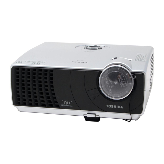
Page 16: Names Of Each Part On The Main Unit
Names of each part on the main unit (10) (11) Back Name (1) Lens (2) Infrared remote sensor (3) Foot adjuster release button : Press to set up or stow the foot adjuster. (4) Air exhaust (5) Control panel (6) Zooming lever (7) Focusing ring (8) Air intake (9) AC IN socket... -
Page 17: Names Of Each Part On The Control Panel And Remote Control
Names of each part on the control panel and remote control Control panel POWER KEYSTONE + KEYSTONE - CAUTION • Do not look into the laser light source of the remote control or direct the laser pointer toward a person or a mirror. •... -
Page 18: Label Locations
Name (12) Laser indicator (13) Mouse control button (14) PAGE+/- button (15) MUTE button (16) FREEZE button (17) Remote control ON/OFF switch : Switches on/off the remote control. (18) R-CLICK button (19) L-CLICK button Note • For the remainder of this manual, buttons are referred to as follows: Selection buttons ⇒... -
Page 19: Parts On The Rear Panel
Parts on the rear panel Name (1) MONITOR terminal (2) COMPUTER IN terminal (3) S-VIDEO terminal (4) VIDEO terminal (5) AUDIO IN terminal (6) CONTROL terminal (7) AUDIO OUT terminal (8) Antitheft lock hole ( 1 ) ( 2 ) ( 3 ) ( 4 ) ( 5 ) ( 8 ) : Main Function... -
Page 20: Preparing And Using The Remote Control
Preparing and using the remote control ■ Loading dry-cell batteries into the remote control Remove the battery cover. Insert the dry-cell batteries. Be sure to align the plus and minus ends of the batteries properly. Two batteries (LR03, SIZE AAA) are used. -
Page 21: Operating A Computer Using The Remote Control
XP OS, that is equipped with a USB port which can support USB1.1 (The mouse remote control receiver is also supported on OS 9 or OS X for the Macintosh). However, please note that Toshiba does not guarantee the operation of all computers. Connecting a computer Connect the mouse remote control receiver (supplied) to a computer. -
Page 22: Placement
Placement Placement Styles As shown in the figures below, this device can be placed in 4 different styles. The factory setting is “floor-mounted front projection.” Set the [Projection mode] in the Default setting menu , in accordance with your needs. p.36 Floor-mounted front projection Floor-mounted rear projection... -
Page 23: Projection Distance And Size
Projection Distance and Size Use the figures, tables, and formulas below to determine the projection size and projection distance. (Projection sizes are approximate values for full-size picture with no keystone adjustment.) As seen from above Screen As seen from the side Lens center a is the distance (m) between the lens and the screen, and corresponds to a range of 1.36 m to 11 m. -
Page 24: Connection
Connection Before connection • Read the owner’s manual of the device you are connecting to the projector. • Some types of computer cannot be used or connected to this projector. Check for an RGB output terminal, supported signal • Turn off the power of both devices before connecting. •... -
Page 25: Turning The Power On And Off
Turning the power on and off ■ Connecting the power cord Insert the power cord connector into the AC IN socket of the projector. Insert the power cord plug into a wall or other power outlet. ■ Removing the lens cover ■... -
Page 26: Turning The Power Off
■ Turning the power off Press the ON/STANDBY button. A message appears on the screen, confirming that you wish to shut off the power. This message will disappear after a moment. (This operation is no longer valid after the message disappears.) Press the ON/STANDBY button again. -
Page 27: Basic Operations
Basic operations Turn on the power. Turn on the power by following the instructions in “Turning the power on” Select the language (When using the first time). When the projector is used for the first time after purchase,the start menu for language(to display the menus and messages on screen) and confugration is dis- played in English.(if the screen is out of focus,adjust it according to the step ... -
Page 28: Adjusting The Screen Size And Focus
Projector placement angle adjustments The placement angle and the height of the projected image can be adjusted by the foot adjuster. Lift up the front of the projector to the desired angle, then press the foot adjuster release button. The foot adjuster extends. -
Page 29: Using Handy Features
Using handy features ■ Using auto setting This function sets up the projector to the optimum state such as sampling phase, frequency, screen position, and clamp for each type of the input signal by using simple operations. Press the remote control’s AUTO SET button. For computer input, the Notes •... -
Page 30: Cutting Off The Picture And Sound Temporarily (Mute)
■ Cutting off the picture and sound temporarily (Mute) When you want to project the images of another projector, overhead projector, etc. temporarily, this projector’s images and sound can be turned off. Press the remote control’s MUTE button. The picture and sound are cut off. (The Mute function is released when pressing the MUTE button again.) Notes •... - Page 31 Using handy features (Continued) Select [On] and press press Enter a 4 digit number for the password using numeric key of the remote control. The input number appears as [****]. Re-enter the same password for confirmation. When the password is confirmed the setting is complete and the password be- comes [On].
-
Page 32: Using The Menus
Using the menus You can call up on-screen menus, and conduct a number of adjustments and settings us- ing the operation buttons p.17 ■ How to use the menus The menu shown below is for operation instructions purposes and might differ from the actual display. -
Page 33: The Image Adjustment Menu
■ The image adjustment menu Use this menu to set or adjust image-related items. Items that can be set or adjusted are marked with “Yes”, and those that cannot are marked with “No”. (When an item is masked, it indicates that you cannot select for the current input.) Item Picture mode Toggle the picture mode with Bright/Standard/True color(RGB) -
Page 34: The Display Setting Menu
[Background] • TOSHIBA is set for [Logo] by factory setting. Description Lower Higher... -
Page 35: The Default Setting Menu
Using the menus (Continued) ■ The default setting menu This menu shows placement status and other settings. Item Projection Sets projection mode in accordance with Placement Style. mode (Standard) Auto input Set whether the input with signals is only selected or not. search Language Select one of the languages below to use for displaying the menu... -
Page 36: Displaying Information (Status Display)
Using the menus (Continued) ■ Displaying Information (Status display) This displays information about the input signal, lamp use time, etc. Item Input Input source name Resolution Resolution (in dots) Video mode Color method of video signal Picture mode A group of Pre-set display mode Lamp time Time of lamp use Version... -
Page 37: About Lamp
If this happens, replace it with a new one. WARNING • If the projector is mounted on the ceiling, it is recommended to use your Toshiba dealer- ship when the lamp has to be exchanged. - Page 38 Lamp replacement (Continued) Unplug power cord. Wait until lamp is sufficiently cooled. Wait for at least 1 hour. Remove the lamp cover. Loosen the two screws, raise the outer lamp cover with your fingers as shown to remove the outer lamp cover. Use care to avoid any damage to nails and/or tip of your finger(s).
- Page 39 Reset the lamp timer. See the lamp’s manual for instructions on resetting the lamp timer. Notes and Precautions • It is recommended that the lamp be replaced after 2,000 hours of use.When [Lamp time] reaches 2,000 hours,the appear when the power is on at the first time every 100 hours.) This display disappears when you press the button.
-
Page 40: Lens And Main Unit Cleaning
Lens and main unit cleaning WARNING • Request cleaning and maintenance of a ceiling-mounted unit from your projector dealership. Attempting to clean/replace the lamp at a high site by yourself may cause you to fall down, thus resulting in injury. ■... -
Page 41: Trouble Indications
Trouble indications The indicator lights inform you of interminal abnormalities. No power POWER ⇒ Problem with projector • Unplug the power cord, and contact your dealer. Lamp went out during use, or won’t come on ⇒ Lamp temperature is high so that it is difficult to turn on, the lifetime of POWER the lamp has ended or the projector is malfunctioning. -
Page 42: Before Calling Service Personnel
Before calling service personnel If you think something is wrong, check the followings before contacting customer service. Please see “Trouble indications” If This Happens Check No power • Is the power cord plugged in? Is it connected to the projector? •... -
Page 43: Specifications
Specifications ■ List of general specifications Item Consumption Power Weight External Dimensions (including protruding parts) Cabinet material Conditions for usage environment Display pixels Picture elements Lens Lamp Projection screen size Projection distance Speaker CONTROL terminal COMPUTER(Y/P IN terminal VIDEO terminal MONITOR terminal AUDIO OUT terminal Notes... -
Page 44: List Of Supported Signals (Rgb Signals)
Specifications (Continued) ■ List of supported signals (RGB signals) This projector supports the following RGB signals. Note, however, that depending on the computer model, the screen may show flicker or streaking. Please adjust the projector if this happens. Resolution VGA_60 VGA_72 640x480 VGA_75... -
Page 45: List Of Supported Signals (Y/Pb/Pr Signals)
■ List of supported signals (Y/P Signal format * 480i(525i)@60Hz 480p(525p)@60Hz * 576i(625i)@50Hz 576p(625p)@50Hz 720p(750p)@60Hz 720p(750p)@50Hz 1080i(1125i)@60Hz 1080i(1125i)@50Hz ■ List of supported signals (Video, S-Video signals) Video mode NTSC SECAM PAL-M PAL-N PAL-60 NTSC4.43 ■ Pin assignment of COMPUTER IN & MONITOR terminals Mini D sub 15 Pin connector Input Signal •... -
Page 46: Control Terminal
■ CONTROL terminal ● Pin assignment Mini DIN 8 pin connector Notes • Contact your dealer for control cable and commands. Pin No. Signal Name Receiving data No connection No connection Signal ground No connection No connection Sending data Signal ground Description...