Table of Contents
Advertisement
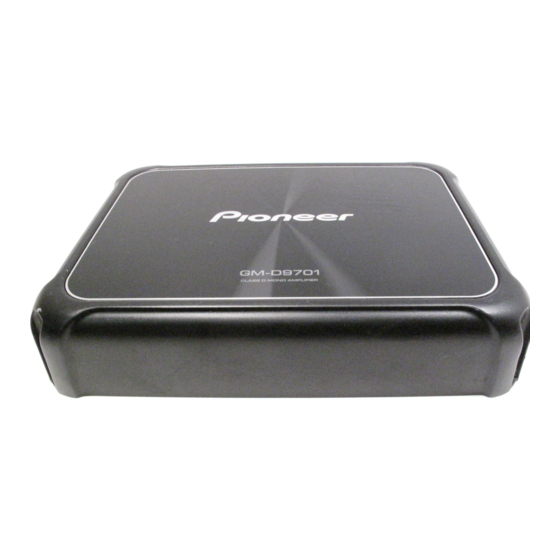
CLASS D MONO AMPLIFIER
GM-D9701
GM-DX971
GM-D9701
GM-D9701
PIONEER CORPORATION
PIONEER ELECTRONICS (USA) INC. P.O. Box 1760, Long Beach, CA 90801-1760, U.S.A.
PIONEER EUROPE NV Haven 1087, Keetberglaan 1, 9120 Melsele, Belgium
PIONEER ELECTRONICS ASIACENTRE PTE. LTD. 2 Jalan Kilang Barat, #07-01, Singapore 159346
PIONEER CORPORATION 2019
/XEVEW5
/XEVES
28-8, Honkomagome 2-chome, Bunkyo-ku, Tokyo 113-0021, Japan
GM-D9701/XEVUC
/XEVUC
ORDER NO.
CRT6388
/XEVUC
K-ZZZ JAN. 2019
Advertisement
Table of Contents

Related Manuals for Pioneer GM-D9701/XEVUC


Summary of Contents for Pioneer GM-D9701/XEVUC
- Page 1 PIONEER CORPORATION 28-8, Honkomagome 2-chome, Bunkyo-ku, Tokyo 113-0021, Japan PIONEER ELECTRONICS (USA) INC. P.O. Box 1760, Long Beach, CA 90801-1760, U.S.A. PIONEER EUROPE NV Haven 1087, Keetberglaan 1, 9120 Melsele, Belgium PIONEER ELECTRONICS ASIACENTRE PTE. LTD. 2 Jalan Kilang Barat, #07-01, Singapore 159346 PIONEER CORPORATION 2019 K-ZZZ JAN.
-
Page 2: Table Of Contents
8. EACH SETTING AND ADJUSTMENT ..........................8 9. EXPLODED VIEWS AND PARTS LIST..........................8 9.1 PACKING SECTION ...............................8 9.2 EXTERIOR SECTION..............................10 10. SCHEMATIC DIAGRAM ..............................12 10.1 P.C.B TOTAL ASSY ..............................12 11. PCB CONNECTION DIAGRAM ............................13 11.1 P.C.B TOTAL ASSY ..............................13 12. ELECTRICAL PARTS LIST ...............................15 GM-D9701/XEVUC... -
Page 3: Service Precautions
When the parts that are fixed by BRACKET (IC40, IC41, IC44, Q20, Q21, Q22, Q23, Q24, Q25, Q26, Q27, Q515, Q516, Q517, Q518, Q519, Q520, D42, D43, D44 and D45) replace, follow the below procedure. Caution : While the picture shown is slightly different from this model in shape, the replacing procedure is the same. GM-D9701/XEVUC... -
Page 4: Others
For environmental protection, lead-free solder is used on the printed circuit boards mounted in this unit. Be sure to use lead-free solder and a soldering iron that can meet specifications for use with lead-free solders for repairs accompanied by reworking of soldering. GM-D9701/XEVUC... -
Page 5: Specifications
Sound interrupted 3.2 JIGS LIST - Lubricants and Glues List Name Grease No. Remarks Grease GEM1057 Applying to BRACKET Bond GYL1006 Applying to P.C.B TOTAL ASSY 4. BLOCK DIAGRAM There is not information to be shown in this chapter. GM-D9701/XEVUC... -
Page 6: Diagnosis
7. DISASSEMBLY Note: While the photograph shown is slightly different from this model in shape, the disassembly procedure is the same. - Removing the Chassis (Fig. 1) Remove 6 pcs screw and then remove the Chassis. Chassis Fig. 1 GM-D9701/XEVUC... - Page 7 - Removing the P.C.B Total Assy (Fig. 2 and Fig.3) BRACKET Remove 11 pcs screw and remove BRACKET. Fig. 2 BRACKET Remove a screw. Remove 12 pcs screw and remove the P.C.B Total Assy. Fig. 3 P.C.B Total Assy Bonding Position GYL1006 GM-D9701/XEVUC...
-
Page 8: Each Setting And Adjustment
Screw adjacent to mark on the product are used for disassembly. For the applying amount of lubricants or glue, follow the instructions in this manual. (In the case of no amount instructions,apply as you think it appropriate.) 9.1 PACKING SECTION Except GM-D9701/XEVES GM-D9701/XEVUC... - Page 9 Box,Outer Carton See Contrast table (2) Warranty Card See Contrast table (2) Speaker Input Wire with RCA Pin Cord L008201020030S (2) CONTRAST TABLE GM-D9701/XEVUC, GM-DX971/XEVUC, GM-D9701/XEVEW5 and GM-D9701/XEVES are constructed the same except for the following: Mark Description GM-D9701/XEVUC GM-DX971/XEVUC...
-
Page 10: Exterior Section
9.2 EXTERIOR SECTION GM-D9701/XEVUC... - Page 11 B020030081W10SV Screw,Tap Tite B020030081B10SV Screw 1500001206010SV Bracket 4010216766200V Bracket 4010216766100V Screw 1507041146010SV (2) CONTRAST TABLE GM-D9701/XEVUC, GM-DX971/XEVUC, GM-D9701/XEVEW5 and GM-D9701/XEVES constructed the same except for the following: Mark Description GM-D9701/XEVUC GM-D9701/XEVES GM-DX971/XEVUC GM-D9701/XEVEW5 Heat Sink Assy 7025CX1801113 7025CX1801114 7025CX1801113 7025CX1801113 P.C.B Total Assy...
-
Page 12: Schematic Diagram
10. SCHEMATIC DIAGRAM NOTE : P.C.B TOTAL ASSY Symbol indicates a resistor. Note: When ordering service parts, be sure to refer to " EXPLODED VIEWS AND PARTS LIST" or No differentiation is made between chip "ELECTRICAL PARTS LIST". resistors and discrete resistors. FREQ Symbol indicates a capacitor. -
Page 13: Pcb Connection Diagram
11.PCB CONNECTION DIAGRAM Capacitor NOTE FOR PCB DIAGRAMS Connector 1.The parts mounted on this PCB P.C.B TOTAL ASSY SIDE A include all necessary parts for SIDE A several destination. For further information for respective destinations, be sure to check with the schematic dia- SIDE B BASS BOOST REMOTE CONTROL P.C.Board... - Page 14 P.C.B TOTAL ASSY SIDE B...
-
Page 15: Electrical Parts List
The expression of the unit in this manual is shown by u instead of . Please do not make a mistake. Circuit Symbol and No. Part No. Circuit Symbol and No. Part No. Q 13 SEMI,CHIP TR/NPN 2SC J522437900010S A:GM-D9701/XEVUC Q 14 SEMI,CHIP TR/NPN 2SC J522555100010S B:GM-DX971/XEVUC C:GM-D9701/XEVEW5 Q 15 SEMI,CHIP TR/NPN 2SC... - Page 16 C 37 D041470085230S RCA2 TER,RCA 4PIN(A,C,D) G602413F00000S RCA2 TER,RCA 4PIN(B) G602413FG0000S C 40 D041102085240S SPEAK1 TER,BOARD SCREW G6180WB040340S C 41 D041102085240S POWER2 TER,BOARD SCREW G6180WB030330S C 44 D041470085230S > FUSE2 HOLDER,FUSE 40 A G6400BXS30100S C 45 D041470085230S C 48 D041470085230S GM-D9701/XEVUC...
- Page 17 D041221084230S C 573 D02410206C060S C 574 D02410206C060S C 575 D02410506H060S C 577 D02410606H060S C 579 D02410606H060S C 576 D04110008H050S C 609 D041470084230S C 612 D041470084230S C 620 D041010087230S Miscellaneous Parts List VR,ROTARY 10 kohm(BASS BOOST) C450901100010S CN51 JACK,MODULAR G4060RJ220010S GM-D9701/XEVUC...