Table of Contents
Advertisement
Advertisement
Table of Contents

Related Manuals for Janome MC350E


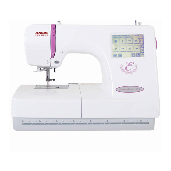
Summary of Contents for Janome MC350E
-
Page 2: Table Of Contents
GENERAL TROUBLESHOOTING PROCEDURE Changing External Parts (1) Face Cover ............. 1 Changing External Parts (2) Belt Cover ............... 2 Changing External Parts (3) Base Cover ............. 3 Changing External Parts (4) Bed Cover/Base Lid (2) .......... 4 Changing External Parts (5) Base ............... 5 Changing External Parts (6) Front Cover ............. -
Page 3: Changing External Parts (1) Face Cover
MC350E Changing External Parts (1) Face Cover Replacing th face cover To remove: 1. Remove the Cap and Screw and remove the Face Cover Screw Face cover To attach: 2. Follow the above procedure in reverse. -
Page 4: Changing External Parts (2) Belt Cover
MC350E Changing External Parts (2) Belt cover Replacing the belt cover To remove: 1. Remove the Cap and Screw 2. Raise the Carrying Handle and remove the Screw 3. Lay the machine on its back and remove Screws (2 pcs. gold color), then remove the Belt cover... -
Page 5: Changing External Parts (3) Base Cover
MC350E Changing External Parts (3) Base Cover Replacing the base cover To remove: 1. Remove Screws (4 pieces) to remove the base cover Screws Base cover To attach: 2. Follow the above procedure in reverse. -
Page 6: Changing External Parts (4) Bed Cover/Base Lid (2)
MC350E Changing External Parts (4) Bed Cover / Base Lid (2) Replacing the bed cover To remove: 1. Remove the base cover. (See page 3) 2. Remove Screw (2 pcs.), and remove the Base 3. Remove Screw (2 pcs.), and remove the Bed... -
Page 7: Changing External Parts (5) Base
MC350E Changing External Parts (5) Base Base To remove: 1. Remove the Belt cover. (See page 2) 2. Remove Setscrew (4 pcs.), and remove the base unit . 3. Remove the X-Motor Connector and Y-Motor Connector from the printed circuit board “A”. -
Page 8: Changing External Parts (6) Front Cover
MC350E Changing External Parts (6) Front Cover Front cover To remove: 1. Remove the face cover, belt cover, base cover. (See pages 1-4). 2. Remove Screw and remove the Arm thread guide (lower) 3. Remove Screw 4. Loosen Screws 3 turns. -
Page 9: Changing External Parts (7) Rear Cover
MC350E Changing External Parts (7) Rear Cover Rear cover To remove: 1. Remove the face cover and belt cover. (See page 1,2) 2. Loosen Screw , and remove the rear cover. Screw Screw Screw Screw To attach: 3. Follow the above procedure in reverse. -
Page 10: Adjusting Needle Drop Position
MC350E Adjusting Needle Drop Position The needle should be positioned at the center of the needle plate hole. 1. Lower the needle to its lowest position by turning the handwheel. 2. Remove the face cover and loosen Screw move the Needle bar supporter... -
Page 11: Adjusting Hook Timing
MC350E Adjusting Hook Timing The hook timing is that amount of ascending travel of the needle bar from its lowest position to where the tip of the rotary hook meets the left side of the needle should be 3.1 to 3.7 mm. -
Page 12: Adjusting Needle Bar Height
MC350E Adjusting Needle Bar Height The standard distance between the top of the needle eye and the upper surface of the hook race should be in the range of 1.6 - 2.0 mm when the rotary hook meets the left side of the needle in ascending travel of needle from its lowest position. -
Page 13: Adjusting Clearance Between Needle And Hook
MC350E Adjusting Clearance between Needle and Hook The clearance between needle and rotary hook should be - 0.1 to + 0.05 mm. 1. Remove the needle plate, bobbin holder, base cover and bed cover (See pages 3 - 4). Replace the needle with the Test pin 2. -
Page 14: Adjusting Backlash Between Hook Drive Gear And Lower Shaft Gear
MC350E Adjusting Backlash between Hook Drive Gear and Lower Shaft Gear The rotary play of the hook should be 0.8 mm or less. Adjust the backlash after the adjustment of the clearance between needle and rotary hook. To check: 1. Turn the power switch “OFF”. -
Page 15: Adjusting Height Of The Needle Stop Position
MC350E Adjusting Height of the Needle Stop Position The standard height of needle stop position should be 14.2 mm above the needle plate surface when the machine is topped. 1. Remove the front cover unit. (See page 6) 2. Turn the power switch “ON” and press Start / Stop button twice. -
Page 16: Adjusting Thread Tension
MC350E Adjusting Thread Tension The standard upper thread tension should be 51 to 59 grams when the tension dial is set at “3”, measured with a #50 polyester thread being pulled at approximately 110 mm/sec. in the direction of arrow. -
Page 17: Adjusting Tension Release Mechanism
MC350E Adjusting Tension Release Mechanism When the presser foot lifter is raised, the tension release mechanism should work correctly. If not, adjust as follows. 1 Remove the front cover unit. (see page 6) 2 Lower the presser foot lifter, set the thread tension dial at “9”... -
Page 18: Changing Thread Tension Unit
MC350E Changing Thread Tension Unit Replacing the thread tension unit To remove: 1. Remove the front cover unit. (see page 6) 2. Remove Screws 3. Remove the thread tension unit. To attach: 4. Follow the above procedure in reverse. Note: After the replacement, adjust “Thread Tension Release Machanism”... -
Page 19: Replacing Threader Plate And Adjustment
MC350E Replacing Threader Plate and Adjustment If the hook on the threader plate is damaged, replace it by following the instructions below. To replace (Fig. 1): 1. Remove the presser foot. 2. Push down the Threader supporter plate remove from the Pin . -
Page 20: Adjusting Height Of Embroidery Foot P
MC350E Adjusting Height of Embroidery Foot P Attach the Foot (P), and the space between the needle plate and the bottom surface of the Foot (P) should be 1.0 to 1.6 mm, when the needle bar is at its lowest position. -
Page 21: Connector Connection Diagram
MC350E Connector Connection Diagram Please see the following connector connection diagram for the printed circuit board “A” (Main board). LCD Harness Presser foot lifter sensor (Red) Bobbin winder sensor (Blue) Upper thread sensor (Red) Touch panel Upper shaft sensor (Black) Printed circuit board “F”... -
Page 22: Replacing Printed Circuit Board "A" (Main Board)
MC350E Replacing Printed Circuit Board “A” (Main board) To remove: 1. Remove the front cover. (See page 6) 2. Pull out the connectors of printed circuit board F LCD Harness, Inverter and Touch panel. 3. Remove Screws (5 pieces) and the Printed circuit board “A”... -
Page 23: Replacing Touch Panel
MC350E Replacing Touch Panel To remove: 1. Remove the front cover. (See page 6) 2. Pull out the Connectors of Printed circuit board “F” (Start/Stop) , LCD Harness and Inverter connector and Touch panel connectors 3. Remove Screws (4 pieces) and remove the... -
Page 24: Replacing Printed Circuit Board "F" & "F2
MC350E Replacing Printed Circuit Board “F” & “F2” Printed circuit board F2 To remove: 1. Remove the front cover. (See page 6) 2. Pull out the connector from the printed circuit board “A” (Mainboard). 3. Remove Screws (2 pieces) and remove the Printed circuit board “F” (Start/Stop) To attach: 4. -
Page 25: Adjustment Of The Solenoid
MC350E Adjustment of the Solenoid 1. Remove the front cover. (see page 6) 2. Loosen the setscrews 3. Adjust the clearance of Solenoid 1.6 mm with the tension disk closed. 4. Tighten the setscrew Setscrews Clearance of solenoid The plunger is drawn in direction of Arrow... -
Page 26: Replacing Dc Motor And Motor Belt Tension Adjustment
MC350E Replacing DC Motor and Motor Belt Tension Adjustment Replacing DC Motor 1. Remove the belt cover. (See page 2) 2. Remove the motor belt. 3. Remove the Motor connector from the printed circuit board “A” (Main board). 4. Remove Screws (2 pieces) and replace the motor. -
Page 27: Replaching Carriage Plate (Unit)
MC350E Replacing Carriage Plate (Unit) To remove: 1. Turn the power switch “ON” and select the pattern No.1. 2. Turn the power switch “OFF” and remove the Cover . (Unlock the hook from the inside.) 3. Turn the power switch “ON” to return the carriage to the home position. -
Page 28: Adjusting X And Y Sensors
MC350E Adjusting X and Y Sensors To adjust X and Y sensors: 1. Turn the power “ON” to return the carriage to the home position. (X-1) 2. Turn the power “OFF” and then remove the base 69.0 mm unit. (X-2) 2.5 mm 3. -
Page 29: Adjusting X And Y Sensors (Simple Adjustment)
MC350E Adjusting X and Y Sensors (Simple Adjustment) To adjust X and Y sensor (without removing the base unit): 1. Remove the base cover.(see page 3) 2. Remove the presser foot and attach the Embroidery hoop “A” 3. Turn the power “ON” and select the pattern No.1... -
Page 30: Adjusting X Mortor Gear
MC350E Adjusting Carriage Motor Gear If the carriage motor gear sounds noisy when sewing the embroidery stitches, follow the instructions below. 1. Remove the base unit (See page 5). 2. Remove Screw and Nylon clip 3. Attach the X and Y motor connectors to printed circuit board “A”... -
Page 31: Replacing Switching Power Supply
MC350E Replacing Switching Power Supply Replacement of Switching Power Supply To remove: 1. Remove the face cover, belt cover, front cover and rear cover. 2. Remove Screws and remove the machine socket and fixing plate. 3. Pull out the Machine socket unit connector 4. - Page 32 MC 350E PARTSLIST...
- Page 33 MC 350E PARTSLIST Parts # Description Needle plate (unit) 854621004 Needle plate 854104006 Hook cover plate supporter 846030005 Setscrew 2x4 000097613 Hook cover plate release button 825016000 Spring 825017001 Setscrew 2x2.3 820374004 Rotation stopper 846222109 Needle plate setscrew 820390109 Hook cover plate 846271103 860002002 Needle plate positioning pin...
- Page 34 MC 350E PARTSLIST...
- Page 35 MC 350E PARTSLIST Parts # Description 852605154 Needle bar supporter (unit) 751014006 Needle bar supporter 000111902 Hexagonal socket screw 3x4 830609518 Needle bar (unit) 857602008 Threader positioning setting plate (unit) 751047008 Needle bar connecting stud 000111201 Hexagonal socket screw 4x4 857037006 Threader positioning setting plate 751016008...
- Page 36 MC 350E PARTSLIST...
- Page 37 MC 350E PARTSLIST Parts # Description Clutch base plate (unit) 854625008 Clutch base plate 854111006 Clutch starting lever 854112007 Snap ring E3 000002105 Clutch arm 2 854113008 Clutch arm 854114009 Clutch arm 2 spring 854115000 Snap ring E 4 000002507 Setscrew 4x8 000081005 Rod (unit)
- Page 38 MC 350E PARTSLIST...
- Page 39 MC 350E PARTSLIST Parts # Description 852009004 Presser bar bushing 830030006 Presser bar spring 830029002 Presser bar 830810042 Embroidery foot P 763048006 Setscrew 830586035 Presser bar supporter (unit) 000111500 Hexagonal socket screw 4x8 000116608 Washer 5 830035012 Presser foot lifter 822072005 Presser foot lifter pin 850546002...
- Page 40 MC 350E PARTSLIST...
- Page 41 MC 350E PARTSLIST Parts # Description Upper shaft (unit) 854639108 Setscrew 4x12 000101703 Setscrew 3x6 000078319 Hexagonal socket screw 5x4 000110901 Hexagonal socket screw 5x8 000111706 Upper shaft front bushing 829042007 Washer 10x0.5 000038605 Upper shaft ring 639095000 Hexagonal socket screw 5x5 000111304 Upper shaft shielding plate 830095010...
- Page 42 MC 350E PARTSLIST...
- Page 43 MC 350E PARTSLIST Parts # Description Hook race (unit) 854629002 Bobbin holder stopper (unit) 846632003 Magnet 627190010 Washer 4 000070506 Setscrew 4x8 000081005 Bobbin holder (unit) 846652102 Bobbin 102261103 Lower shaft ring (unit) 820672005 Lower shaft ring 820166001 Hexagonal socket screw 4x4 000111201 Washer 8x0.5 000038502...
- Page 44 MC 350E PARTSLIST...
- Page 45 MC 350E PARTSLIST Parts # Description 852631001 Front cover (whole unit)(JAI,JCA) 852631104 Front cover (whole unit)(JNBV,JA,JUK,JLA) 852016705 Front cover 852610004 LCD (unit) 852017005 LCD set plate (upper) 852611005 LCD set plate (lower) (unit) 850612103 Inverter (unit) 852505005 LCD harness (unit) 852633003 Printed circuit board A (unit) 852019018...
- Page 46 MC 350E PARTSLIST...
- Page 47 MC 350E PARTSLIST Parts # Description Bobbin winder (unit) 854640009 Bobbin winder (unit) 852509009 Spring 823119008 Bobbin winder set plate 854140004 Snap ring E5 000001609 Bobbin winderswitch (unit) 852615009 Micro switch (unit) 852510003 switchset plate2 852042009 Insulation paper 852014002 Setscrew 1.7x6 000041209 Setscrew 4x8 000081005...
- Page 48 MC 350E PARTSLIST...
- Page 49 MC 350E PARTSLIST Parts # Description Thread cutter (unit) 852634004 Thread cutter (unit) 860625007 Setscrew 4X8 000081005 Thread cutter cover set plate 852057007 Setscrew 3X4 000101105 Needle thread solenoid (unit) 854631007 Needle thread solenoid (unit) 854508004 Solenoid set plate 854127005 Setscrew 2.6X4 000163806 Thread drawing leverArm...
- Page 50 MC 350E PARTSLIST...
- Page 51 MC 350E PARTSLIST Parts # Description 851617008 Idler (unit) 851039000 Idler base 625217100 Idler 000002806 Snap ring E6 000081005 Setscrew 4x8 852032006 Carrying handle supporter (rear) 853614207 Belt cover (unit) 852031304 Belt cover 832099009 Belt cover attaching plate(1) 000161103 Setscrew 3x6(B) 000078319 Setscrew 3x6 000115009...
- Page 52 MC 350E PARTSLIST...
- Page 53 MC 350E PARTSLIST Parts # Description 852617104 Base (unit) 830150003 Rubber foot 820350004 Adjusting screw 820351005 Spring 605074008 Rubber foot 813123004 Snap ring CS 850151017 Base lid 810220106 Setscrew 832146002 Base lid (1) 851053103 Base cover 000101426 Setscrew 4x6 000101127 Setscrew 3x4 850147205 Sheet cover...
- Page 54 MC 350E PARTSLIST...
- Page 55 MC 350E PARTSLIST Parts # Description 852801004 Standard accessories (unit) 102261103 Bobbin 102403109 Felt 802424004 Lint brush 820832005 Screwdriver (large) 822814007 Scissors 625031500 Additional spool pin 822019509 Spool holder (small) 852802108 Needle (unit) 829803004 Spool stand 653802002 Screwdriver 822020503 Spool holder (large) 852850008 Instruction book (unit)(JAI) 852850101...