ADC HiGain HMS-318 List 3 User Manual
Higain managed shelf 19-inch, 3190 mechanic, 22-slot managed co shelf
Hide thumbs
Also See for HiGain HMS-318 List 3:
- Quick installation manual (32 pages) ,
- Installation manual (40 pages)

Related Manuals for ADC HiGain HMS-318 List 3


Summary of Contents for ADC HiGain HMS-318 List 3
-
Page 1: User Manual
® HiGain Managed Shelf 19-inch, 3190 Mechanic, 22-Slot Managed CO Shelf (HMS-318 List 3) User Manual CLEI: T1MF2S04RA Product Catalog: HMS-318 List 3 Document Number: LTPH-UM-1261-01... - Page 2 Contents herein are current as of the date of publication. ADC reserves the right to change the contents without prior notice. In no event shall ADC be liable for any damages resulting from loss of data, loss of use, or loss of profits, and ADC further disclaims any and all liability for indirect, incidental, special, consequential or other similar damages.
-
Page 3: Table Of Contents
About This Manual ...ix Introduction ...ix Audience ...ix Related Publications ...ix Organization ...ix Conventions ...x EU Compliance ...xi Safety Guidelines ...xi Inspecting Your Shipment ... xii Chapter 1: Product Description ... 1-1 Typical HMS-318 List 3 Shelf Applications ... 1-2 Power and Alarm Connections ... - Page 4 Table of Contents December 20, 2004 LTPH-UM-1261-01...
- Page 5 List of Figures Figure 1-1. HMS-318 List 3 Shelf - Front View ... 1-2 Figure 1-2. HMS-318 List 3 Shelf - Rear View ... 1-3 Figure 1-3. Input Power Terminal Block (TB1) ... 1-5 Figure 1-4. Alarms Wire-Wrap Field (TB2) ... 1-6 Figure 1-5.
- Page 6 List of Figures December 20, 2004 LTPH-UM-1261-01...
-
Page 7: List Of Tables
List of Tables Table 1-1. HMS-318 List 3 Shelf Rear-Panel Connections (LPS-300C) ... 1-4 Table 1-2. Alarms Wire-wrap Field Functional Description ... 1-7 Table 1-3. J26 – RS-232/X.25 Management Port (DTE) ... 1-12 Table 1-4. J27 – AUX RS-232 Management Port (DTE) ... 1-13 Table 2-1. - Page 8 List of Tables December 20, 2004 viii LTPH-UM-1261-01...
-
Page 9: About This Manual
Central Office (CO) or telco-style equipment rack. UDIENCE This manual is written for people who install and plan the installation of ADC products in a Central Office environment. If you are an installer, technician, or a local craft person, this manual contains information you can use to install the HMS-318 List 3 shelf. - Page 10 Provides power requirements, physical dimensions, recommended operational and storage environments, and accessories for the HMS-318 List 3 shelf. Provides information on how to contact the ADC Technical Support group. Defines abbreviations and acronyms used in this document and that relate to the HMS-318 List 3 shelf.
-
Page 11: Eu Compliance
December 20, 2004 Reader Alert Alerts you to possible data loss, service-affecting procedures, or other similar type CAUTION problems Alerts you that failure to take or avoid a specific action might result in hardware damage or WARNING loss of service Alerts you that failure to take or avoid a specific action might result in personal harm DANGER EU C... -
Page 12: Inspecting Your Shipment
• Unpack each container and visually inspect the contents for signs of damage. If the equipment has been dam- aged in transit, immediately report the extent of damage to the transportation company and to ADC. Order replacement equipment, if necessary. - Page 13 • 1.544 Mbps (T1) full-duplex transmission over two unconditioned, non-loaded copper loops • DSX-1 interfaces at the CO and the remote end, with remote provisioning and performance monitoring • CO power modules (LPS-300C) which provide xDSL span powering to ADC’s LoopStar (AP) solution.
-
Page 14: Typical Hms-318 List 3 Shelf Applications
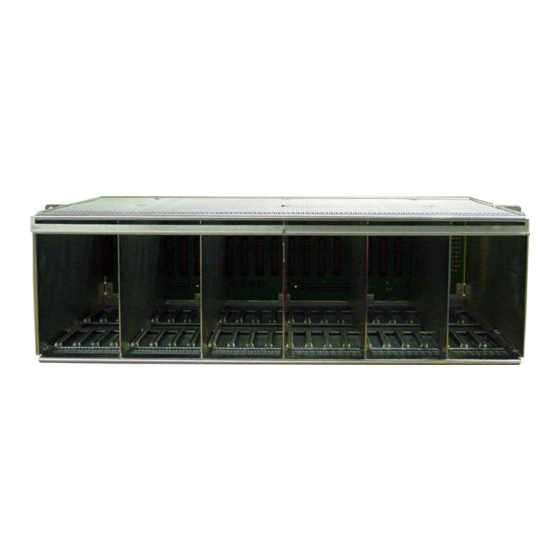
Chapter 1: Product Description HMS-318 L YPICAL Capable of using various components in different types of applications, the HMS-318 List 3 shelf is designed as a very adaptable shelf. It can be used in the following applications: • Managed HDSLx configuration - HMU-319 (HiGain Management Unit) with HLU-319, H2TU-C-319, or H4TU-C- 319 (HiGain Line Unit) configuration •... - Page 15 December 20, 2004 HMS-318 List 3 Rear View The HMS-318 List 3 shelf input power, 5-position terminal block (labeled TB1) and the alarms (labeled Alarms) wire- wrap connections are located on the rear panel (see upper right corner extension of the right panel. The label (BONDING WIRE MIN #10 AWG) is located on the right corner of the rear panel (see Grounding Lug and Hexhead Screw, Managed HDSLx configuration Also located on the rear panel, connectors P1 and P2 (labeled CO PAIR 1 and 2) are DSX-1 receive and transmit...
- Page 16 Chapter 1: Product Description Table 1-1. HMS-318 List 3 Shelf Rear-Panel Connections (LPS-300C) Connector/Terminal Block BNC-T (Female) RJ-45 RS-232 DB-25 (Female) RS-232 DB-25 (Female) Amphenol 50-pin (Male) Amphenol 50-pin (Male) Amphenol 50-pin (Male) Amphenol 50-pin (Male) J1 - J22 20-pin wire-wrap J1 - J22 20-pin wire-wrap DIN 96-pin (Female)
- Page 17 December 20, 2004 OWER AND LARM ONNECTIONS The HMS-318 List 3 shelf has a separate split input power (TB1) and an Alarms wire-wrap field (TB2). The following paragraphs provide information about TB1 and TB2. Safety Precautions Observe the following general precautions and recommendations in planning the source power requirements for the HMS-318 List 3 shelf (for additional safety information, please refer to the section describing the on page xi):...
- Page 18 Chapter 1: Product Description Alarms Wire-Wrap Field Before making power connections (CO primary power feeds A and B) to the HMS-318 List 3 shelf, IMPORTANT ensure that the Main CO power breaker is off. Otherwise, severe injury to the installer or damage to the unit may result.
- Page 19 December 20, 2004 In the HMU/HLU configuration, for example, for detailed information about the different types of alarms, refer to the “Managing Alarms” section in the HMU-319, H2TU-C-319, or H4TU-C-319 User describes the types of alarms the HMU-319 reports, when the alarm occurs, and how to respond to the alarm using the ACO.
- Page 20 Chapter 1: Product Description HDSL, HDSL2, ONNECTING TO The following paragraphs provide information on making DSX-1 and HDSL, HDSL2, and HDSL4 connections to the HMS-318 List 3 shelf. Plug-in Connections DSX-1 and HDSL, HDSL 2, or HDSL4 DSX-1 connections to the HMS-318 List 3 shelf can be made through the HMS-318 List 3 shelf’s rear-panel 50-pin Amphenol-type male connectors P1, RCV to DSX (labeled CO PAIR 1) and P2, XMT from DSX (labeled CO PAIR 2).
- Page 21 December 20, 2004 DSX-1 Tip 1 (OUT) HDSL Loop 1 - Tip HDSL Loop 2 - Tip Notes: Minor alarm output is normally floating (0 to -60V maximum) and a ground (10 ma maximum, +5 Vdc for HLU-319 List 2D) when activated Fuse alarm is normally floating (0 to -80V maximum) and at -48V (10 ma maximum) when activated Figure 1-5.
- Page 22 Chapter 1: Product Description DSX-1 DSX-1 Tip 1 (OUT) HDSL4 Loop 1 Tip System Alarm * Frame Ground HDSL4 Loop 2 Tip Factory use only Notes: System alarm and management bus reserved. Fuse alarm normally floating (0 to -80 Vdc maximum) and at -48Vdc (10 ma maximum) when activated.
- Page 23 December 20, 2004 Wire Wrap Connections – Span Powered xDSL Figure 1-8 shows the LPS-300C slot pinouts on the HMS-318 List 3 shelf rear panel for xDSL circuits. xDSL A IN xDSL B IN xDSL A OUT Frame Ground xDSL B OUT Notes: System alarm and managem ent bus reserved.
- Page 24 Chapter 1: Product Description RS-232/X.25 R EMOTE ANAGEMENT Two EIA RS-232 communications ports, J26 (labeled OS RS232 PORT) and J27 (labeled AUX RS232 PORT), located on the HMS-318 List 3 shelf rear panel (see management interfaces for connection to a HiGain system. OS communications port connector, and communications port connector.
-
Page 25: Heat Dissipation Factors
December 20, 2004 Table 1-4. J27 – AUX RS-232 Management Port (DTE) Pin No. THERNET EMOTE ANAGEMENT The BNC connector J24 (labeled 10 BASE-2), see to 32 shelves into an integrated network through a 10 BASE-2 (Thinnet) Ethernet LAN (IEEE.802.3). The rear-panel RJ-45 connector J25 (labeled 10 BASE-T), see Ethernet LAN (both IEEE.802.3 compatible). - Page 26 Chapter 1: Product Description Note: Refer to the respective ADC card user manuals to determine the maximum number of cards that can be installed in a shelf before exceeding the maximum heat dissipation density of the telco-style equipment rack configuration.
-
Page 27: Air Flow Guidelines
December 20, 2004 UIDELINES To ensure adequate air flow through the telco-style equipment rack, it is recommended that you maintain a clearance of at least 6 inches (15.2 cm) in the front and the back of the rack at all times. If airflow through the telco-style equipment rack and the shelves that occupy it is blocked or restricted, or if the ambient air being drawn into the rack is too warm, an over temperature condition within the rack and the shelves that occupy it can occur. - Page 28 Chapter 1: Product Description December 20, 2004 1-16 LTPH-UM-1261-01...
-
Page 29: Chapter 2: Installation
NSTALLATION This section provides specific information about preparing your site for installation. Included are specific preparatory information, safety guidelines, specific rack-mounting guidelines, adapter bracket mounting, rack mounting, DSX and HDSL or Span Powered xDSL connections, and power and alarm connections. Once you have completed the basic installation and verified that your shelf is functioning properly, you can refer to the instruction manuals for the individual modules (HLU, HMU, or LPS-300C). - Page 30 To reduce the potential damage to the product, transport the shelf in its ADC-specified packaging. Failure to do so may result in damage to the shelf. Also do not remove the shelf from its shipping container until you are ready to install it. Refer to page xii for unpacking instructions.
- Page 31 December 20, 2004 Notes: Required Tools The following tools are required to install the shelf: • Grounding or ESD-preventive wrist strap • #2 Phillips-head screwdriver • #1 Phillips-head screwdriver • Straight-slot-head screwdriver • Cable preparation tools • A -inch open-end wrench •...
-
Page 32: Safety Guidelines
Chapter 2: Installation AFETY UIDELINES The safety guidelines (see Chapter 1: “Safety Guidelines” on page to protect your equipment. The list on page iv may not identify all potentially hazardous situations in your working environment, so be alert and exercise good judgment at all times. HMS-318 L OUNTING THE Each HMS-318 List 3 shelf has a hardware kit. - Page 33 December 20, 2004 Adapter Bracket Mounting Procedure (19-inch Telco-style Equipment Rack) Adapter bracket placement depends on the type of telco-style rack you plan to use to install the HMS-318 List 3 shelf. First, check the mounting adapter brackets on the shelf to determine whether the factory-installed configuration is correct for the planned telco-style equipment rack installation.
- Page 34 Chapter 2: Installation Step Locate the mounting holes of the HMS-318 List 3 shelf for the desired rack width 23 inches (58.4 cm) and position (2- or 5-inch recess mounting). Align each adapter bracket with the HMS-318 List 3 shelf and attach to the desired rack width 23 inches (58.4 cm) and position (2- or 5-inch recess mounting) with the #6-32 x .25 inch screws (provided).
-
Page 35: Dsx-1 And Hdslx Connections
December 20, 2004 Rack Mounting Procedure To secure the HMS-318 List 3 shelf to the telco-style rack, you must use the mounting screws provided or follow your local practices for installing the shelves into your telco-style equipment rack. Ensure that the adapter brackets have been securely fastened [see page 2-5,... -
Page 36: Span Powered Xdsl Connections
Chapter 2: Installation DSX and HDSL Connector Procedure Step Complete one of the following steps to make the DSX-1 and HDSLx connections to the shelf using one of the following methods: Plug the DSX-1 interface cables into P1 and P2 and the HDSLx interface cables into P3 and P4. - Page 37 December 20, 2004 ONDING AFETY ROUND NPUTS IMPORTANT Before making connections to the HMS-318 List 3 shelf, ensure that the Main CO power breaker is off. Otherwise, severe injury to the installer or damage to the unit may result. Bonding (safety) ground, power and frame ground, and alarm connections and cabling are marked for ease of installation [see ground lug location (labeled BONDING WIRE MIN #10 AWG)], TB1, and TB2 on the rear panel of the HMS-318 List 3 Shelf, and the following procedures for proper safety ground, power, alarm, and optional fan (alarms) connections (see...
- Page 38 Chapter 2: Installation Step Looking at the HMS-318 List 3 rear panel, find the ground lug location (labeled BONDING WIRE MIN #10 AWG) on the upper right corner extension of the right panel (see Measure between the telco-style rack and the HMS-318 List 3 Shelf the correct length of a #10 AWG (minimum) ground wire so that it reaches the ground lug location on the HMS-318 List 3 Shelf, and cut.
- Page 39 December 20, 2004 Power and Frame Ground Procedure To avoid voltage differences from building up between the shelf ground (GND) bus and the IMPORTANT ground pins of the management terminal that connects to the RS-232 ports, connect the shelf ground pins and the terminal ground bus to the TB1 FGND (frame ground) pin. Step Use locally approved practices to connect #12 AWG (minimum) power wiring from -48Vdc Office Battery to -48VA and -48VB terminals on TB1-1 and TB1-2 (see <Cross-Ref>Figure 2).
- Page 40 Chapter 2: Installation Optional Fan Alarm Procedure Note: The FAN terminals wire-wrap field provides access to the Normally Open (NO), Form A fan relay contact located on the HMU-319 management unit. A temperature monitor activates this fan relay when the shelf temperature exceeds 45°C (±1°C) and deactivates the relay when the temperature drops below 35°C (±1°C).
-
Page 41: Installing The Hmu-319 With Hlu-319, H2Tu-C-319, H4Tu-C-319
December 20, 2004 HMU-319 NSTALLING THE Install the line units (HLUs) into slots 1 through 22 and the HMU-319 management unit into slot 23 of the HMS-318 List 3 shelf (see “HMS-318 List 3 Shelf - Front View” on page 1-2 Install HMU and HLU Procedure Use anti-static wrist-straps connected to the ESD Jack (located on the right adapter bracket, see Figure 1 on page 3) when inserting a circuit card. - Page 42 Chapter 2: Installation Install LPS-300C Procedure Use anti-static wrist-straps connected to the ESD Jack (located on the right adapter bracket, see Figure 1-1 on page 1-2) when inserting a circuit card. Avoid touching components on the circuit card. ATTENTION Step Hold the LPS-300C Power Module vertically with the front of the circuit card toward you.
-
Page 43: Appendix A: Signal And Pin Assignments
IGNAL AND SSIGNMENTS The Tip and Ring signal and pin assignments to the HMS-318 List 3 shelf are: • P1-DSX-1 Receive or xDSL B IN, Tip and Ring (see • P2-DSX-1 Transmit or xDSL A IN, Tip and Ring (see •... - Page 44 Appendix A: Signal and Pin Assignments Cable Pin Number Connector P2 - DSX-1 Transmit or Span Powered xDSL (xDSL A IN) Table A-2 provides signal and pin assignment information for making DSX-1 transmit or Span Powered xDSL (xDSL A IN) circuit connections to the HMS-318 List 3 shelf. Table A-2.
- Page 45 December 20, 2004 Cable Pin Number LTPH-UM-1261-01 Appendix A: Signal and Pin Assignments Slot Card Slot Pin Number Ring Ring Ring Ring Ring Ring Ring Ring Ring Ring Ring Ring Ring Ring Ring...
- Page 46 Appendix A: Signal and Pin Assignments Connector P3 - HDSL Span 1 (HDSL, HDSL2, or HDSL4) or Span Powered xDSL (xDSL A OUT) Table A-3 provides connector P3 signal and pin assignment information for making HDSL Span 1 (HDSL, HDSL2, or HDSL4) or Span Powered xDSL (xDSL A OUT) connections to the HMS-318 List 3 shelf.
- Page 47 December 20, 2004 Cable Pin Number Connector P4 - HDSL Span 2 (HDSL, HDSL2, or HDSL4) or Span Powered xDSL B OUT Table A-4 provides signal and pin assignment information for making HDSL Span 2 (HDSL, HDSL2, or HDSL4) or Span Powered xDSL (xDSL B OUT) connections to the HMS-318 List 3 shelf.
- Page 48 Appendix A: Signal and Pin Assignments Cable Pin Number Slot Ring Ring Ring Ring Ring Ring Ring Ring Ring Ring Ring December 20, 2004 Card Slot Pin Number LTPH-UM-1261-01...
-
Page 49: Appendix B: Standard Pic Color Code
PIC C TANDARD OLOR This appendix lists the standard PIC color codes in tabular format with the Pair Number cross-referenced with the colors of the Tip and Ring wires used by the installer. Pair Number LTPH-UM-1261-01 Table B-1. Standard PIC Color Code White White White... - Page 50 Appendix B: Standard PIC Color Code December 20, 2004 LTPH-UM-1261-01...
-
Page 51: Appendix C: Circuit Card Preventive Measures
IRCUIT REVENTIVE This appendix describes the preventive measures that should be observed for the following: • Handling and storing of circuit cards. • Installing/replacing circuit cards sensitive to static electricity. ANDLING IRCUIT ARDS Damage to circuit cards, particularly those that are sensitive to static electricity, may occur at any time. Follow these safeguards when handling circuit cards. - Page 52 Appendix C: Circuit Card Preventive Measures Circuit Card Ejector Tab or Built-in Thumb Hold Most circuit cards have an ejector tab that is used to assist the installer in inserting and removing each circuit card. These ejector tabs are typically located at either the top or bottom of the circuit card. Other types of circuit cards have a built-in thumb hold for gripping the card.
- Page 53 PECIFICATIONS Power Requirements CO Battery Fuse Compliance NEBS Safety Physical Dimensions (HxWxD) Weight Capacity Mounting Operational Environment Temperature Humidity Altitude Storage Environment Temperature Humidity LTPH-UM-1261-01 Appendix Voltage -48 Vdc nominal (-42.5 Vdc to -56.5 Vdc) Maximum 15 A GR-63-CORE, Issue 2 GR-1089-CORE, Issue 3 SR-3580, Level 3 UL/cUL 60950-1...
-
Page 54: Appendix D: Specifications
Appendix D: Specifications Accessories Supplied Accessories Available a.If fuse size and wire gauge requirements are not specific, follow local practices for determining your fuse and wire gauge size. Brackets (attached at factory) for mounting in either 19-inch (48.3 cm) or 23-inch (58.4 cm) bays Brackets for mounting in ETSI rack Extender Bracket Kit: available in three colors: EB-52, gray;... -
Page 55: Appendix E: Product Support
UPPORT ADC Customer Service Group provides expert pre-sales support and training for all of its products. Technical support is available 24 hours a day, 7 days a week by contacting the ADC Technical Assistance Center. Sales Assistance: 800.366.3891 Systems Integration: 800.366.3891 ADC Technical Assistance Center: 800.366.3891... - Page 56 Appendix E: Product Support December 20, 2004 LTPH-UM-1261-01...
-
Page 57: Glossary
LOSSARY ACO – Alarm Cutoff AUD – Audible (alarm) AUX – Auxiliary port AWG – American Wire Gauge CLEI – Common Language Equipment Interface CO – Central Office COM – Common CRIT – Critical (alarm) DSL – Digital Subscriber Loop DSX-1 –... - Page 58 Glossary December 20, 2004 OS port – Operator Services port PIC – Plastic Insulated Conductor RCV – Receive RMA – Return Material Authorization RX – Receive SYS ID – System Identifier (alarm) T1 – 1.544 Mbps data rate (North American) VIS –...
- Page 59 The FCC requires the user to be notified that any changes or modifications made to this device that are not expressly approved by ADC voids the user’s warranty. All wiring external to the products should follow the provisions of the current edition of the National Electrical Code.
- Page 60 World Headquarters ADC Telecommunications, Inc. PO Box 1101 Minneapolis, MN 55440-1101 USA For Technical Assistance Tel: 800.366.3891 ® HiGain Managed Shelf 19-inch, 3190 Mechanic, 22-Slot Managed CO Shelf (HMS-318 List 3) User Manual CLEI: T1MF2S04RA Product Catalog: HMS-318 List 3...