Siemens SINAMICS G120 Operating Instructions Manual
Hide thumbs
Also See for SINAMICS G120:
- List manual (1256 pages) ,
- Manual (732 pages) ,
- Operating instructions manual (550 pages)

Related Manuals for Siemens SINAMICS G120


Summary of Contents for Siemens SINAMICS G120
- Page 1 SINAMICS G120 Control Units CU240E CU240S CU240S DP CU240S DP-F CU240S PN CU240S PN-F Operating Instructions · 03/2009 SINAMICS Answers for industry.
- Page 3 Introduction Description Connection SINAMICS Commissioning SINAMICS G120 CU240S and CU240E Control Functions Units, FW 3.2 Servicing and maintenance Operating Instructions Messages and fault codes Technical data Edition 03/2009, FW 3.2 03/2009 A5E02440075B AA...
-
Page 4: Commissioning
Note the following: WARNING Siemens products may only be used for the applications described in the catalog and in the relevant technical documentation. If products and components from other manufacturers are used, these must be recommended or approved by Siemens. Proper transport, storage, installation, assembly, commissioning, operation and maintenance are required to ensure that the products operate safely and without any problems. -
Page 5: Table Of Contents
Table of contents Introduction..............................9 About this manual ..........................9 Fast track commissioning ......................10 Adapting inverters to the application (parameterization for entry level personnel)......11 1.3.1 General basics ..........................11 1.3.2 Parameter ............................12 1.3.3 Parameters with follow-on parameterization................13 Frequently required parameters....................14 Extended adaptation options (parameterization for advanced level personnel)......16 1.5.1 BICO technology: basic principles ....................16 1.5.2... - Page 6 Table of contents Commissioning with the operator panel..................71 4.6.1 Function of the Basic Operator Panel ..................71 4.6.2 BOP controls and displays ......................72 4.6.3 Parameterization with the BOP (two examples) ................. 73 4.6.4 Commissioning steps ........................74 4.6.5 Commissioning V/f control ......................
- Page 7 Table of contents Evaluating the frequency inverter status..................124 5.9.1 Assigning specific functions to digital outputs................124 5.9.2 Assigning certain functions to analog outputs ................126 5.10 Technological functions ......................128 5.10.1 Braking functions of the frequency inverter ................128 5.10.1.1 DC and compound braking ......................130 5.10.1.2 Dynamic braking ........................133 5.10.1.3 Regenerative braking.........................135 5.10.1.4 Parameterizing a motor holding brake..................136...
- Page 8 Table of contents Technical data ............................227 Technical data, CU240S Control Unit ..................227 Technical data, CU240E Control Unit ..................228 General technical data, PM240 Power Modules............... 229 Power-dependent technical data, PM240 Power Modules ............230 General technical data, PM250 Power Modules............... 233 Power-dependent technical data, PM250 Power Modules ............
-
Page 9: Introduction
– Function diagrams of all of the inverter functions – A list of the fault messages and alarms ● As download: All of the operating instructions, manuals on SINAMICS G120 (http://support.automation.siemens.com/WW/view/en/22339653/133300) ● On DVD: SD Manual Collection - all manuals on low-voltage motors, geared motors and low-voltage inverters, 5 languages. -
Page 10: Fast Track Commissioning
Introduction 1.2 Fast track commissioning Fast track commissioning Procedure when commissioning 1. Required components – Power Module, Control Unit; optional: Operator panel or PC connection kit 2. Installing the inverter -> Chapter 3.3 (Page 30) – Installing the Power Modules (minimum clearances, components) -> Chapter 3.3.1 (Page 31) –... -
Page 11: Adapting Inverters To The Application (Parameterization For Entry Level Personnel)
Introduction 1.3 Adapting inverters to the application (parameterization for entry level personnel) Adapting inverters to the application (parameterization for entry level personnel) 1.3.1 General basics Parameterizable inverters transform standard motors into variable-speed drives Inverters are parameterized to adapt them to the motor being driven so that this can be optimally operated and protected. -
Page 12: Parameter
Introduction 1.3 Adapting inverters to the application (parameterization for entry level personnel) 1.3.2 Parameter Parameter types There are two types of parameters, adjustable and display parameters. Adjustable parameters Adjustable parameters are represented with four digits preceded by the letter "P". You can change the value of these parameters within a defined range. -
Page 13: Parameters With Follow-On Parameterization
Introduction 1.3 Adapting inverters to the application (parameterization for entry level personnel) 1.3.3 Parameters with follow-on parameterization When you change certain parameters, the system may automatically change other parameters accordingly. This makes it much easier to parameterize complex functions. Example: Parameter P0700 (command source) Parameter P0700 can be used to switch the command source from the fieldbus to digital inputs. -
Page 14: Frequently Required Parameters
Introduction 1.4 Frequently required parameters Frequently required parameters Parameters that in many cases help Table 1- 1 This is how you filter the parameter list to keep the number of displayed parameters transparent Parameter Description P0003 = User access level 1: Standard: Allows access to the most frequently used parameters (factory setting) 2: Extended: Extended access, e.g. - Page 15 Introduction 1.4 Frequently required parameters Table 1- 6 This is how you select the setpoint source for the frequency Parameters Description P1000 = 0: No main setpoint 1: MOP setpoint 2: Analog setpoint (factory setting for non-fieldbus-capable inverters) 3: Fixed frequency 4: USS at RS 232 5: USS on RS 485 6: Fieldbus (factory setting for fieldbus-capable inverters)
-
Page 16: Extended Adaptation Options (Parameterization For Advanced Level Personnel)
Introduction 1.5 Extended adaptation options (parameterization for advanced level personnel) Extended adaptation options (parameterization for advanced level personnel) 1.5.1 BICO technology: basic principles Functional principle of BICO technology and inverter closed/open-loop control functions The inverter software offers a range of open/closed-loop control functions, communication functions, as well as various diagnostics and operating functions. - Page 17 Introduction 1.5 Extended adaptation options (parameterization for advanced level personnel) BICO parameters You can use the BICO parameters to define the sources of the input signals of a function. This means that using BICO parameters you can define from which connectors and binectors a function reads-in its input signals.
- Page 18 Introduction 1.5 Extended adaptation options (parameterization for advanced level personnel) Table 1- 12 Connector and binector output symbols Abbreviation and symbol Description Function Binector/connector output When do you need to use BICO technology? BICO technology allows you to adapt the inverter to a wide range of different requirements. This does not necessarily have to involve highly complex functions.
-
Page 19: Bico Technology: Example
Introduction 1.5 Extended adaptation options (parameterization for advanced level personnel) 1.5.2 BICO technology: example Example: Shifting a basic PLC functionality into the inverter A conveyor system is to be configured in such a way that it can only start when two signals are present simultaneously. - Page 20 Introduction 1.5 Extended adaptation options (parameterization for advanced level personnel) Explanations of the example Open the default signal interconnection for BICO parameterization The default setting P0701 = 1 indicates the following internal signal interconnection: P0840 r0722.0 DI 0 OFF1 Terminal 5 Figure 1-4 Default parameterization The setting P0701 = 99 means that a pre-assigned signal interconnection is disconnected...
-
Page 21: Description
Description Overview of the SINAMICS G120 family of inverters Thanks to their modular design, SINAMICS G120 inverters can be used in a wide range of applications with respect to functionality and power. Each SINAMICS G120 inverter comprises a Control Unit and a Power Module. The power range extends from 0.37 kW to 250 kW. - Page 22 Description 2.1 Modularity of the converter system Supplementary components In addition to the main components, the following components are available for commissioning and parameterization: Operator Panel (OP) for parameterization, diagnostics, and control as well as for copying drive parameters. MMC memory card for carrying out standard commissioning of more than one inverter and for external data backup.
-
Page 23: Overview Of Control Units
Description 2.2 Overview of Control Units Overview of Control Units Figure 2-1 Control Unit variants CU240S and CU240E Control Units, FW 3.2 Operating Instructions, 03/2009, A5E02440075B AA... -
Page 24: Overview Of Power Modules
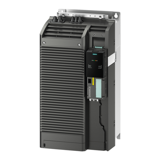
Description 2.3 Overview of Power Modules Overview of Power Modules Figure 2-2 Power Module versions A number of Power Module versions are available for different line supply voltages in a power range from between 0.37 kW and 250 kW. Depending on the Power Module used, the energy released in regenerative mode is either ●... -
Page 25: Reactors And Filters
Description 2.4 Reactors and filters Reactors and filters Overview Depending on the Power Module, the following combinations with filters and reactors are permitted: Power Module Line-side components Load-side components Line reactor Line filters Braking Sine-wave filter Output reactor class B resistor PM240 ●... -
Page 27: Connection
Installation sequence 1. Install the Power Module (detailed instructions are provided in the Installation Manual for the Power Modules (http://support.automation.siemens.com/WW/view/en/30563173/133300)) – Remove the terminal covers - where applicable – Connect motor cable and power cable – Terminate the shield over a large area, if necessary using a shield connection set –... -
Page 28: Mounting Reactors And Filters
Connection 3.2 Mounting reactors and filters Mounting reactors and filters Mounting system components in a space-saving fashion for the inverters Many system components for the inverters are designed as sub-chassis components, that is, the component is mounted on the baseplate and the inverter mounted above it to save space. - Page 29 Connection 3.2 Mounting reactors and filters PM250 Power Power supply supply Output Line Line reactor Power filter filter Power module module to the motor Basic layout of a PM250 Power Module with class Basic layout of a PM250 Power Module with a B line filter as a base component class B line filter as a base component CU240S and CU240E Control Units, FW 3.2...
-
Page 30: Mounting Power Modules
Connection 3.3 Mounting Power Modules Mounting Power Modules Options for installing the Power Module Depending on the format, various options are available for installing inverters. This manual describes how to install inverters directly on the cabinet wall. Installation options Frame size Installation on standard rails Mounting on a cabinet panel with shield connection kit Installation directly on the cabinet wall... -
Page 31: Dimensions, Hole Drilling Templates, Minimum Clearances, Tightening Torques
Connection 3.3 Mounting Power Modules 3.3.1 Dimensions, hole drilling templates, minimum clearances, tightening torques Overview of dimensions and hole drilling templates for the Power Modules 0.37 kW … 1.5 kW 2,2 kW … 4 kW 7,5 kW … 15 kW Retaining type Retaining type Retaining type... - Page 32 Connection 3.3 Mounting Power Modules 18.5 kW … 30 kW without filter 18.5 kW … 30 kW with filter for PM240 and PM250 11 kW … 18 kW for PM260 4 x M6 bolts Retaining type • 4 x M6 nuts •...
- Page 33 Connection 3.3 Mounting Power Modules 37 kW … 45 kW without filter 37 kW … 45 kW with filter 4 x M6 bolts Retaining type • 4 x M6 nuts • 4 x M6 washers • 6 Nm (53 lbf.in) Tightening torques •...
- Page 34 Connection 3.3 Mounting Power Modules 55 kW … 132 kW without filter for PM240 and PM250 55 kW … 90 kW with filter 30 kW … 55 kW for PM260 4 x M8 bolts Retaining type • 4 x M8 nuts •...
- Page 35 Connection 3.3 Mounting Power Modules 160 kW … 250 kW for PM240 6 x M8 bolts Retaining type • 6 x M8 nuts • 6 x M8 washers • 13 Nm (115 lbf.in) Tightening torques • Lateral: 0 mm (0 inch) Clearances to other devices •...
-
Page 36: Wiring Power Modules
Connection 3.3 Mounting Power Modules 3.3.2 Wiring Power Modules Prerequisites Once the Power Module has been properly installed, the line and motor connections can now be established. The following warning information must be observed here. WARNING Line and motor connections The inverter must be grounded on the supply and motor side. - Page 37 Connection example: Power Module PM240 Figure 3-1 Connection diagram: PM240 Power Module with Brake Relay Star connection and delta connection With SIEMENS motors, you will see a diagram of both connection types on the inside of the terminal board cover: • Star connection (Y) •...
- Page 38 Connection 3.3 Mounting Power Modules Connecting-up Power Modules Line supply connection Motor connection Connect the braking resistor Connect the line supply to terminals Connect the motor at terminals U2, V2, A braking resistor can be connecting at U1/L1, V1/L2 and W1/L3. and W2.
-
Page 39: Emc-Compliant Connection
Connection 3.3 Mounting Power Modules 3.3.3 EMC-compliant connection EMC-compliant connection The example diagram shows how shielding is implemented for frame size FSA using a shield connection kit. Corresponding shield connection kits are available for all Power Module frame sizes (you will find more information in Catalog D11.1). The cable shields must be connected to the shield connection kit with the greatest possible surface area by means of the shield clips. - Page 40 Connection 3.3 Mounting Power Modules Avoiding electromagnetic disturbances The inverters are designed for operation in industrial environments where high values of electromagnetic noise and disturbances are expected. Generally, correct installation guarantees safe, reliable and disturbance-free operation. If difficulties do arise, then please note the following guidelines.
-
Page 41: Installing The Control Unit
Connection 3.4 Installing the Control Unit Installing the Control Unit Locating the Control Unit on the power unit The Control Unit is simply snapped-on to a Power Module. This also establishes all of the electrical connections between the two components. The Control Unit can be removed by pressing the release button ③. -
Page 42: Interfaces, Connectors, Switches, Control Terminals, Leds On The Cu
Connection 3.4 Installing the Control Unit 3.4.1 Interfaces, connectors, switches, control terminals, LEDs on the CU Overview of the process and user interfaces The following interfaces are provided on the Control Unit ● Terminals for the input and output signals ●... - Page 43 Connection 3.4 Installing the Control Unit Figure 3-4 Block diagram, CU 240 CU240S and CU240E Control Units, FW 3.2 Operating Instructions, 03/2009, A5E02440075B AA...
- Page 44 Connection 3.4 Installing the Control Unit Arrangement and function of the terminals on the CU240S Control Unit All Control Units are equipped with the same control terminals. However, depending on the CU version, the factory set activation for certain digital inputs and interfaces differ. (see the block diagram for CU240S/E and for CU240S-DP/CU240S-DPF/CU240S-PN/CU240S-PN- Unlike the standard Control Units, the fail-safe Control Units CU240S DP-F and CU240S PN-F only have six digital inputs instead of nine.
-
Page 45: Commissioning
Commissioning Alternative commissioning options The functions of an inverter are activated and configured using parameters. Parameters can either be accessed from the operator control/display instrument (operator panel) or using the STARTER commissioning tool from the PC via the appropriate inverter interface. Inverters can also be parameterized by saving the valid inverter parameter set on an MMC memory card or on the Operator Panel and then transferring it to a different inverter with the same configuration and function. -
Page 46: Initial Coupling Of The Cu And Pm - Message F0395
Commissioning 4.1 Initial coupling of the CU and PM - message F0395 Initial coupling of the CU and PM - message F0395 Description Message "F0395" is displayed when Control Units or Power Modules are switched on for the first time or after they have been replaced. Using this message F0395, the two inverter components - Control Unit and Power Module - are monitored to ensure that they are not replaced without the appropriate authorization. -
Page 47: Restoring The Factory Settings
Commissioning 4.2 Restoring the factory settings Restoring the factory settings If nothing else works, restore the factory settings! You can restore the factory setting using parameter P0970. Table 4- 1 Restoring the factory settings Parameter or Description procedure P0003 = 1 User access level 1: Standard P0010 = 30... -
Page 48: Preparing Commissioning
Motor data / data on the motor rating plate If you use the STARTER commissioning tool and a SIEMENS motor, you only have to specify the motor Order No. In all other cases, you must read-off the data from the motor rating plate and enter into the appropriate parameters. - Page 49 Commissioning 4.3 Preparing commissioning NOTICE Information about installation The rating plate data that you enter must correspond to the connection type of the motor (star connection [Y]/ delta connection [Δ]), i.e. for a delta motor connection, the delta rating plate data must be entered. In which region of the world is the motor used? - Motor standard [P0100] ●...
- Page 50 Commissioning 4.3 Preparing commissioning What command and setpoint sources are you using? The command and setpoint sources that are available depend on the inverter. Depending on whether you use an inverter with or without fieldbus interface, with or without fail-safe functions, the default command and setpoint sources set in the factory differ.
-
Page 51: Commissioning With Factory Settings
Commissioning 4.4 Commissioning with factory settings Commissioning with factory settings Prerequisites for using the factory settings In simple applications, commissioning can be carried out just using the factory settings. This section explains what prerequisites must be fulfilled for this purpose and how they are fulfilled. -
Page 52: Wiring Examples For The Factory Settings
Commissioning 4.4 Commissioning with factory settings 4.4.1 Wiring examples for the factory settings Many applications function using the factory settings To ensure that the factory setting can be used, you must wire the control terminals on your inverter as shown in the following examples. Default settings for the control terminals on the CU240E Figure 4-1 CU240E terminal overview: wiring example for using the factory settings... - Page 53 Commissioning 4.4 Commissioning with factory settings Default settings for the control terminals on the non-bus-capable CU240E Figure 4-2 CU240S terminal overview: wiring example for using the factory settings CU240S and CU240E Control Units, FW 3.2 Operating Instructions, 03/2009, A5E02440075B AA...
-
Page 54: Factory Setting Of The Frequency Inverter
Commissioning 4.4 Commissioning with factory settings 4.4.2 Factory setting of the frequency inverter Default command and setpoint sources Inverters used in automation solutions have the appropriate fieldbus interfaces. These inverters are preset in the factory so that the appropriate control and status signals can be exchanged via the fieldbus interface. - Page 55 Commissioning 4.4 Commissioning with factory settings Parameter Factory setting Meaning of the factory setting Function Access level P0309 Rated motor efficiency (in accordance with the rating plate in %) if P0100 = 0, then P0309 is irrelevant P0310 [Hz] Rated motor frequency (in accordance with the rating plate in Hz) P0311 1395...
-
Page 56: Default Terminal Settings
Commissioning 4.4 Commissioning with factory settings 4.4.3 Default terminal settings Factory settings of the process interfaces Digital inputs Terminal Abbreviation Parameter Factory setting Meaning of the factory setting P0701 ON/OFF1 P0702 Direction reversal P0703 Fault acknowledgment P0704 Fixed frequency selector bit 0 (direct) [P1001] P0705 Fixed frequency selector bit 1 (direct) [P1002] P0706... - Page 57 Commissioning 4.4 Commissioning with factory settings Analog inputs Terminal Abbreviation Parameters Factory setting Meaning of the factory setting AI0+ P0756 [0] Set unipolar voltage input 0 V … +10 V DC AI0- in addition to parameterizing DIP switch on CU housing. AI1+ P0756 [1] Set unipolar voltage input...
-
Page 58: Commissioning With Starter
● The installed STARTER software. (supplied with the PC connection kit). You can download the latest version from the Internet under the following address (http://support.automation.siemens.com/WW/view/en/10804985/133100): ● The motor must be connected to the inverter. CU240S and CU240E Control Units, FW 3.2... -
Page 59: Creating A Starter Project
Commissioning 4.5 Commissioning with STARTER 4.5.1 Creating a STARTER project Description An inverter can be parameterized in a user-friendly fashion using the Project Wizard. The commissioning procedure described here follows the Project Wizard. The PC communicates with the inverter via the USS interface. ●... - Page 60 Commissioning 4.5 Commissioning with STARTER PG/PC - Set interface ● Select "PC COM-Port (USS)" from the list and click on "Properties …" Figure 4-6 Setting the USS interface ● If "PC COM-Port (USS)" is not available, click on "Select …" to install the "PC COM-Port (USS)"...
- Page 61 Commissioning 4.5 Commissioning with STARTER ● If you have installed the "PC COM-Port (USS)" interface, close the dialog box and now call up "Properties - PC COM-Port (USS)". Figure 4-8 PC COM properties ● In this dialog box, you can set the COM interface (COM1, COM2, COM3) and baud rate (default: 38400).
- Page 62 Commissioning 4.5 Commissioning with STARTER ● When you click "OK", the "Set PG/PC Interface" dialog box is displayed again. In the "Set PG/PC Interface" dialog box, you can view the stations that can be accessed via USS by choosing "Diagnostics...": ●...
- Page 63 Commissioning 4.5 Commissioning with STARTER Insert drives Figure 4-9 Insert drives ● In this dialog box, enter a name for your inverter, e.g. "SINAMICS_G120_CU240S" (no blanks or special characters). ● Click on "Next". ● Close the "Summary" dialog box by choosing "Finish". CU240S and CU240E Control Units, FW 3.2 Operating Instructions, 03/2009, A5E02440075B AA...
-
Page 64: Establishing An Online Connection Between The Pc And Converter (Going "Online")
● Click on "Load HW configuration to PG" to download the online data into your PC. Figure 4-10 Inverters found online (using the SINAMICS G120 with Control Unit CU240S DP as example) ● To conclude your entry, choose "Close". -
Page 65: Starting The General Commissioning
"Online mode". Figure 4-11 Going online with STARTER (example with SINAMICS G120) ● For modular inverters that comprise a Control Unit and Power Module, when first powered-up and after replacing a control unit or a Power Module, message F0395 is output. - Page 66 Commissioning 4.5 Commissioning with STARTER Carrying out commissioning The Project Wizard navigates you step-by-step using pull-down menus through the basic settings for your application. ● You get to the next menu item by pressing, choose "Next". Figure 4-12 Start field: commissioning CU240S and CU240E Control Units, FW 3.2 Operating Instructions, 03/2009, A5E02440075B AA...
- Page 67 Commissioning 4.5 Commissioning with STARTER ● For the "Drive functions" menu item, we recommend that motor data identification: "Locked" should be selected. Figure 4-13 Deselecting motor data identification Note Motor data identification Motor data identification is only required for vector control - and it is described there. CU240S and CU240E Control Units, FW 3.2 Operating Instructions, 03/2009, A5E02440075B AA...
- Page 68 Commissioning 4.5 Commissioning with STARTER ● For the menu item "Calculation of the motor data", we recommend that you select "Restore factory settings and calculate motor data". Figure 4-14 Calculating the motor data and restoring the factory setting CU240S and CU240E Control Units, FW 3.2 Operating Instructions, 03/2009, A5E02440075B AA...
- Page 69 Commissioning 4.5 Commissioning with STARTER ● The Project Wizard for the (first) commissioning is concluded with the following summary: Figure 4-15 Completing commissioning ● Finally, choose "Finish". CU240S and CU240E Control Units, FW 3.2 Operating Instructions, 03/2009, A5E02440075B AA...
-
Page 70: Commissioning The Application
Commissioning 4.5 Commissioning with STARTER 4.5.4 Commissioning the application Description ● You can now commission your application using the "Drive Navigator" screens or by using the functions available in the project tree. ● Save your settings so that they are protected against power failure (see below). ●... -
Page 71: Commissioning With The Operator Panel
Commissioning 4.6 Commissioning with the operator panel Commissioning with the operator panel 4.6.1 Function of the Basic Operator Panel The Basic Operator Panel (BOP) offers various commissioning options and ways tosave data and transfer data with the BOP (Page 77). The Basic Operator Panel can be used to commission drives, monitor operation and set individual parameters. -
Page 72: Bop Controls And Displays
Commissioning 4.6 Commissioning with the operator panel 4.6.2 BOP controls and displays How to use the BOP Table 4- 4 Operator controls of the Basic Operator Panel and its functions Function Function / result Status LED Shows parameter numbers, values, and physical units of measure. -
Page 73: Parameterization With The Bop (Two Examples)
Commissioning 4.6 Commissioning with the operator panel 4.6.3 Parameterization with the BOP (two examples) All of the parameter changes, which are made using the BOP, are saved so that they are protected against power failure. Changing a parameter value using the BOP The following description is an example of how to change any parameter using the BOP. -
Page 74: Commissioning Steps
Commissioning 4.6 Commissioning with the operator panel 4.6.4 Commissioning steps The following section provides a step-by-step guide to quick commissioning, which is sufficient for the majority of applications. The first step in commissioning a drive train is to ensure that the inverter and motor are harmonized. - Page 75 Commissioning 4.6 Commissioning with the operator panel Table 4- 9 Motor data in accordance with the specifications on the motor rating plate Parameters Description P0304 = … Rated motor voltage (enter value as specified on the motor rating plate in Volt) 400 [v] (factory setting) The rating plate data entered must correspond to the motor connection type (star/delta) (i.e.
- Page 76 Commissioning 4.6 Commissioning with the operator panel Table 4- 11 Parameters that must be set in every application Parameter Description P1080 = … Minimum frequency 0.00 [Hz] factory setting Enter the minimum frequency (in Hz) at which the motor runs independently of the frequency setpoint.
-
Page 77: Data Backup With The Operator Panel And Memory Card
Commissioning 4.7 Data backup with the operator panel and memory card Data backup with the operator panel and memory card 4.7.1 Saving and transferring data using the BOP The operator panel as a medium to backup and transfer data You can save a parameter set on the operator panel and transfer it to other inverters, e.g. to identically parameterize several devices or to transfer the settings after a device has been replaced. -
Page 78: Saving And Transferring Data Using The Mmc
Commissioning 4.7 Data backup with the operator panel and memory card 4.7.2 Saving and transferring data using the MMC The MMC memory card as a medium for backing up and transferring data You can save a parameter set on the memory card and transfer it to other inverters, e.g. to identically parameterize several devices or to transfer the settings after a device has been replaced. - Page 79 Commissioning 4.7 Data backup with the operator panel and memory card Transferring the parameters from the MMC memory card into the inverter (download) Table 4- 16 Transferring data from the memory card to the inverter Parameters Description P0003 = 3 3: Expert P0010 = 30 30: Initiating parameter transfer...
-
Page 81: Functions
Functions Overview of inverter functions Figure 5-1 Overview of inverter functions CU240S and CU240E Control Units, FW 3.2 Operating Instructions, 03/2009, A5E02440075B AA... - Page 82 Functions 5.1 Overview of inverter functions Functions relevant to all applications The functions that you require in each application are located at the center of the function overview above. The parameters of these functions are provided with a matching basic setting during quick commissioning so that in many cases, the motor can be operated without requiring additional parameterization.
- Page 83 Functions 5.1 Overview of inverter functions Functions required in special applications only The functions, whose parameters you only have to adapt when actually required, are located at the outer edge of the function overview above. The production functions avoid overloads and operating states that could cause damage to the motor, inverter and driven load.
-
Page 84: Inverter Control
Functions 5.2 Inverter control Inverter control 5.2.1 Frequency inverter control using digital inputs (two/three-wire control) Configuring start, stop and direction of rotation reversal using digital inputs If the inverter is controlled using digital inputs, using parameter P0727, you can define how the motor responds when it is started, stopped, and the direction of rotation is changed (reversing). - Page 85 Functions 5.2 Inverter control Table 5- 1 Comparison of the methods for two-wire motor control Control commands Description Two-wire control, method 1 (P0727=0) 1. Control command: Switch the motor on or off 2. Control command: Reverses the motor direction of rotation Two-wire control, method 2 (P0727=0) If CW and CCW rotation are selected simultaneously, the signal that was issued first has priority.
- Page 86 Functions 5.2 Inverter control Table 5- 2 Comparison of the methods for three-wire motor control Control commands Explanation Three-wire control, method 1 (P0727 = 2) 1. Control command: Enable the motor so that it can be switched on or switched off 2.
-
Page 87: Two-Wire Control, Method 1
Functions 5.2 Inverter control 5.2.2 Two-wire control, method 1 Function description This control method uses two control commands as permanent signals. One control command starts/stops the motor, while the other control command changes the direction of rotation. Figure 5-2 Two-wire control using digital inputs, method 1 Table 5- 3 Function table Motor ON... -
Page 88: Two-Wire Control, Method 2
Functions 5.2 Inverter control 5.2.3 Two-wire control, method 2 Function description This control method uses two control commands as permanent signals. CW and CCW rotation of the motor is started and stopped with one control command each. To change the direction, the drive must first decelerate to 0 Hz with OFF1 before the direction reversal signal is accepted. -
Page 89: Two-Wire Control, Method 3
Functions 5.2 Inverter control 5.2.4 Two-wire control, method 3 Function description This control method uses two control commands as permanent signals. Like method 2, CW and CCW rotation can be started/stopped by one control command each. In contrast to method 2, however, the control commands can be switched at any time regardless of the setpoint, output frequency, and direction of rotation. -
Page 90: Three-Wire Control, Method 1
Functions 5.2 Inverter control 5.2.5 Three-wire control, method 1 Function description ● The first control command is a permanent enable signal for starting the motor. When this enable signal is canceled, the motor stops. ● CW rotation is activated with the positive edge of the second control command. ●... -
Page 91: Three-Wire Control, Method 2
Functions 5.2 Inverter control 5.2.6 Three-wire control, method 2 Function description ● The first control command is a permanent enable signal for starting the motor. When this enable signal is canceled, the motor stops. ● The motor is started with the positive edge of the second control command. ●... - Page 92 Functions 5.2 Inverter control Table 5- 12 Parameterizing the function Parameter Description P0700 = 3 Controls the motor using the digital inputs of the inverter P0727 = 3 Three-wire control, method 2 P0701 = 2 The enable signal to power-up the motor is issued with digital input 0 Further options: The enable signal can be issued with any other digital input, e.g.
-
Page 93: Command Sources
Functions 5.3 Command sources Command sources 5.3.1 Selecting command sources Selecting the command source [P0700] The motor is switched on/off via external inverter control commands. The following command sources can be used to specify these control commands: ● Operator control / display instrument (operator panel) ●... -
Page 94: Assigning Functions To Digital Inputs
Functions 5.3 Command sources 5.3.2 Assigning functions to digital inputs Assigning control commands to digital inputs as command sources [P0701…P0709] The digital inputs are pre-assigned with certain control commands in the factory. However, these digital inputs can be freely assigned to a control command. Depending on the Control Unit version, SINAMICS inverters are equipped with up to 9 digital inputs. -
Page 95: Controlling The Motor Via The Fieldbus
Functions 5.3 Command sources 5.3.3 Controlling the motor via the fieldbus Control commands via the fieldbus To control the motor via the fieldbus, the inverter must be connected to a higher-level control via the STARTER software tool. For more information, see Chapter "Operation in fieldbus systems". -
Page 96: Setpoint Sources
Functions 5.4 Setpoint sources Setpoint sources 5.4.1 Selecting frequency setpoint sources Selecting the setpoint source [P1000] The speed of the motor can be set via the frequency setpoint. The following sources can be used to specify the frequency setpoint: ● Analog inputs ●... -
Page 97: Using Analog Inputs As A Setpoint Source
Functions 5.4 Setpoint sources 5.4.2 Using analog inputs as a setpoint source Frequency setpoint via analog input [for P1000 = 2] Analog setpoints are read-in via the corresponding analog inputs. The setting specifying whether the analog input is a voltage input (10 V) or current input (20 mA) must be made via P0756 and in addition using the DIP switches on the Control Unit housing. - Page 98 Functions 5.4 Setpoint sources Table 5- 18 Example: Scaling an analog input to 4 - 20 mA Terminal No. Parameters Description Significance Setting the DIP OFF: Voltage input (factory setting) switch ON: Current input AI0+ P0756 [0] Analog input 1 AI0- AI1+ P0756 [1]...
-
Page 99: Using A Motorized Potentiometer As A Setpoint Source
Functions 5.4 Setpoint sources 5.4.3 Using a motorized potentiometer as a setpoint source Frequency setpoint via motorized potentiometer (MOP) (when P1000 = 1 -> P1031) The 'motorized potentiometer' function simulates an electromechanical potentiometer for entering setpoints. The value of the motorized potentiometer (MOP) can be set by means of the "up"... -
Page 100: Using The Fixed Frequency As A Setpoint Source
Functions 5.4 Setpoint sources 5.4.4 Using the fixed frequency as a setpoint source Frequency setpoint via fixed frequency (P1000 = 3) The fixed frequencies are defined using parameters P1001 to P1004 and can be assigned to the corresponding digital inputs using P1020 to P1023. Table 5- 21 Parameters to directly select frequencies Parameters... -
Page 101: Running The Motor In Jog Mode (Jog Function)
Functions 5.4 Setpoint sources 5.4.5 Running the motor in jog mode (JOG function) Run motor in jog mode [JOG function] The JOG function enables you to carry out the following: ● Test the motor and inverter after commissioning to ensure that they function properly (the first traverse movement, direction of rotation etc.) ●... -
Page 102: Specifying The Motor Speed Via The Fieldbus
Functions 5.4 Setpoint sources Using BICO technology, you can also assign the JOG function to other keys. Table 5- 24 Parameter to assign the JOG function to another button Parameters Description P0003 = 3 3: Expert P1055 = ... Enable JOG CW Possible sources: 722.x (digital inputs) / 19.8 (JOG key on the Operator Panel) / r2090.8 (serial interface) P1056 = ... -
Page 103: Changing Over The Command Data Sets (Manual, Automatic)
Functions 5.5 Changing over the command data sets (manual, automatic) Changing over the command data sets (manual, automatic) Switching operating priority In some applications, the inverter is operated from different locations. Example: Switchover from the automatic mode into the manual mode A central control can switch a motor on/off or change its speed either via a fieldbus or via local switches. - Page 104 Functions 5.5 Changing over the command data sets (manual, automatic) Figure 5-7 CDS switchover in the inverter The command data sets are switched over using parameters P0810 and P0811. Parameters P0810 and P0811 are interlinked to control commands, e.g. the digital inputs of the inverter, using BICO technology.
- Page 105 Functions 5.5 Changing over the command data sets (manual, automatic) Table 5- 25 Command data set changeover using parameters P0810 and P0811. Status of P0810 0 or 1 Status of P0811 The CDS that is current active is gray. Selected parameter index Examples Fieldbus as setpoint...
-
Page 106: Setpoint Preparation
Functions 5.6 Setpoint preparation Setpoint preparation Overview of setpoint calculation The setpoint calculation modifies the speed setpoint, e.g. it limits the setpoint to a maximum and minimum value and using the ramp-function generator prevents the motor from executing speed steps. Figure 5-8 Setpoint calculation in the inverter 5.6.1... -
Page 107: Parameterizing The Ramp-Function Generator
Functions 5.6 Setpoint preparation 5.6.2 Parameterizing the ramp-function generator Parameterizing the ramp-function generator The ramp-function generator in the setpoint channel limits the speed of setpoint changes. This causes the motor to accelerate and decelerate more smoothly, thereby protecting the mechanical components of the driven machine. Ramp-up/down time The ramp-up and ramp-down times of the ramp-function generator can be set independently of each other. - Page 108 Functions 5.6 Setpoint preparation Rounding Acceleration can be "smoothed" further by means of rounding. The jerk occurring when the motor starts and when it begins to decelerate can be reduced independently of each other. Rounding can be used to lengthen the motor acceleration/deceleration times. The ramp- up/down time parameterized in the ramp-function generator is exceeded.
-
Page 109: Closed-Loop Control
Functions 5.7 Closed-loop control Closed-loop control Overview There are two different open-loop and closed-loop control techniques for inverters used with synchronous and induction motors. ● Closed-loop control with V/f-characteristic (called V/f control) ● Field-oriented control technology (called vector control) 5.7.1 V/f control 5.7.1.1 Typical applications for V/f control... -
Page 110: V/F Control With Linear Characteristic
Functions 5.7 Closed-loop control 5.7.1.2 V/f control with linear characteristic Table 5- 30 Setting the control type Parameter Description P0003 = 2 Extended access P1300 = 0 Control type: V/f control with linear characteristic Optimizing the starting characteristics for a high break loose torque and brief overload The inverter can provide a higher voltage in the lower speed range and when accelerating. -
Page 111: V/F Control With Parabolic Characteristic
Functions 5.7 Closed-loop control 5.7.1.3 V/f control with parabolic characteristic Note V/f control with a parabolic characteristic must not be used in applications in which a high torque is required at low speeds. Table 5- 32 Setting the control type Parameter Description P0003 = 2... -
Page 112: Vector Control
Functions 5.7 Closed-loop control 5.7.2 Vector control 5.7.2.1 Typical applications for vector control The vector control can be used to control (closed-loop) the speed and the torque of a motor. Vector control is used in many cases without directly measuring the motor speed. This closed-loop control is known as sensorless vector control. -
Page 113: Commissioning Vector Control
For more information about this function, refer to the parameter list as well as the function diagrams 7000, 7500, 7700, 7800 and 7900 in the List Manual. You will find additional information in the Internet (http://support.automation.siemens.com/WW/view/en/7494205): CU240S and CU240E Control Units, FW 3.2 Operating Instructions, 03/2009, A5E02440075B AA... -
Page 114: Torque Control
Functions 5.7 Closed-loop control 5.7.2.3 Torque control Torque control is part of the vector control and normally receives its setpoint from the speed controller output. By deactivating the speed controller and directly entering the torque setpoint, the closed-loop speed control becomes closed-loop torque control. The inverter then no longer controls the motor speed, but the torque that the motor generates. -
Page 115: Using A Speed Encoder
Functions 5.7 Closed-loop control 5.7.2.4 Using a speed encoder Higher accuracy by using a speed encoder A speed encoder increases the accuracy of the speed and the torque of the vector control for speeds below approx. 10% of the rated motor frequency. Commissioning the speed encoder A speed encoder requires the following commissioning steps: 1. - Page 116 Functions 5.7 Closed-loop control CAUTION Use a shielded cable to connect the speed encoder. The shield must not be interrupted by terminal points between the encoder and inverter. Setting the encoder voltage The encoder voltage is set using the DIP switches at the front of the CU. If you use either a BOP or a PC Connection Kit, you must remove this module in order to be able to access the switches.
- Page 117 Functions 5.7 Closed-loop control Table 5- 38 The most important speed encoder parameters Parameter Description P0003 = 2 Extended access P0400 = … Selecting the encoder type 0: Encoder signal is not evaluated • 2: Encoder with pulse tracks A and B without zero pulse •...
-
Page 118: Protection Functions
Functions 5.8 Protection functions Protection functions The frequency inverter offers protective functions against overtemperature and overcurrent for both the frequency inverter as well as the motor. Further, the frequency inverter protects itself against an excessively high DC link voltage when the motor is regenerating. The load torque monitoring functions provide effective plant and system protection. - Page 119 Functions 5.8 Protection functions Temperature sensing using a temperature sensor Table 5- 39 Parameters to sense the temperature using a temperature sensor Parameters Description P0003 = 2 User access level 2: Extended P0335 = 0 Specify the motor cooling 0: Self-ventilated* - with fan on the motor shaft (IC410* or IC411*) - (factory setting) 1: Forced ventilation* - with a separately driven fan (IC416*) 2: Self-ventilated* and inner cooling* (open-circuit air cooled) 3: Forced ventilated* and inner cooling* (open-circuit air cooled)
-
Page 120: Overcurrent Protection
Functions 5.8 Protection functions 5.8.2 Overcurrent protection Method of operation The maximum current controller (I controller) protects the motor and inverter against overload by limiting the output current. The I controller is only active with V/f control. If an overload situation occurs, the speed and stator voltage of the motor are reduced until the current is within the permissible range. -
Page 121: Limiting The Maximum Dc Link Voltage
Functions 5.8 Protection functions 5.8.3 Limiting the maximum DC link voltage How does the motor generate overvoltage? An induction motor can operate as a generator if it is driven by the connected load, In this case, the motor converts mechanical energy into electrical energy. The motor feeds the regenerative energy back to the inverter. -
Page 122: Load Torque Monitoring (System Protection)
Functions 5.8 Protection functions 5.8.4 Load torque monitoring (system protection) Applications with load torque monitoring In many applications, it is advisable to monitor the motor torque: ● Applications in which the mechanical connection between the motor and load may be interrupted (e.g. - Page 123 Functions 5.8 Protection functions Table 5- 43 Parameterizing the monitoring functions Parameter Description No-load monitoring P2179 = … Current limit for no-load detection If the inverter current is below this value, the message "no load" is output. P2180 = … Delay time for the "no load"...
-
Page 124: Evaluating The Frequency Inverter Status
Functions 5.9 Evaluating the frequency inverter status Evaluating the frequency inverter status Frequency inverter states, such as alarms or faults or different actual value quantities of the frequency inverter can be displayed using digital and analog outputs. The pre-assignments (default settings) can be adapted to the particular plant or system requirements as explained in the following descriptions. - Page 125 Functions 5.9 Evaluating the frequency inverter status Table 5- 45 Setting the functions of the digital outputs Terminal No., significance Parameter Description P0003 = 2 Extended parameter access Digital output 0 P0731 Possible values and functions for P0731, P0732 and P0732: ValueFunction 0 Deactivate digital output Digital output 1...
-
Page 126: Assigning Certain Functions To Analog Outputs
Functions 5.9 Evaluating the frequency inverter status 5.9.2 Assigning certain functions to analog outputs Assigning specific functions to analog outputs Two analog outputs are available, which can be parameterized to display a multitude of variables, e.g. the actual speed, the actual output voltage or the actual output current. Table 5- 46 Factory setting of the analog outputs Terminal No., significance... - Page 127 Functions 5.9 Evaluating the frequency inverter status Table 5- 48 Additional analog output settings Parameter Description P0775 = 0 Permit absolute value Specifies whether or not the absolute value of the analog output is used. If enabled, this parameter will use the absolute value of the value to be output. If the original value was negative, the corresponding bit is set in r0785.
-
Page 128: Technological Functions
Functions 5.10 Technological functions 5.10 Technological functions The inverter offers the following technological functions: ● Braking functions ● Automatic restart and flying restart ● Basic process control functions ● Positioning down ramp ● Logical and arithmetic functions using function blocks that can be freely interconnected Please refer to the following sections for detailed descriptions. - Page 129 Regenerative braking PM250, PM260 Braking methods depending on the drive inverter being used Table 5- 50 Power Modules depending on the braking method SINAMICS G120 Power Module PM240 PM250 PM260 DC and compound braking Dynamic braking...
-
Page 130: Dc And Compound Braking
Functions 5.10 Technological functions ● Dynamic braking Advantages: – defined braking characteristics; no additional motor temperature increase; constant braking torque; in principle, also functions when the power fails Disadvantages: – A braking resistor is required; braking energy is lost as heat; the permissible load of the braking resistor must be taken into account ●... - Page 131 Functions 5.10 Technological functions DC braking after an OFF1 or OFF3 command has the following timing sequence: 1. Initially, the motor speed is reduced along the down ramp of the ramp-function generator until an adjustable speed threshold is reached. 2. Once the motor speed reaches this threshold, the inverter interrupts the braking operation using an internal OFF2 command until the motor is de-magnetized.
- Page 132 Functions 5.10 Technological functions Operating characteristics of compound braking Figure 5-10 Compound braking When the motor is in the regenerative mode, the inverter DC link voltage increases. Compound braking is active depending on the DC link voltage. From a DC link voltage threshold that can be set, the inverters adds a DC current component to the motor current.
-
Page 133: Dynamic Braking
Functions 5.10 Technological functions Parameterizing compound braking Table 5- 52 Parameters to enable and set compound braking Parameter Description P003=3 User access level 3: Expert P1236= Compound braking (entered in %) Parameter P1236 defines the DC current superimposed on the motor current after the DC link voltage threshold V has been exceeded. - Page 134 The ON period set here is only effective if the braking resistor has reached its operating temperature. When required, a cold braking resistor is switched-in independent of this parameter **) SIEMENS resistors are designed for 5% ON period CU240S and CU240E Control Units, FW 3.2 Operating Instructions, 03/2009, A5E02440075B AA...
-
Page 135: Regenerative Braking
Functions 5.10 Technological functions 5.10.1.3 Regenerative braking Regenerative braking applications Regenerative braking is typically used in applications in which braking energy is generated either frequently or for longer periods of time, e.g. centrifuges, unwinders or cranes. Operating characteristics of regenerative braking The inverter can feed back up to 100% of its power (for HO base load) into the line supply. -
Page 136: Parameterizing A Motor Holding Brake
Functions 5.10 Technological functions 5.10.1.4 Parameterizing a motor holding brake Motor holding brake applications The motor holding brake prevents the motor turning when the inverter is switched-off. The inverter has internal logic to control a motor holding brake. The motor holding brake control inside the inverter is suitable for the following typical applications: ●... - Page 137 Functions 5.10 Technological functions Inaktiv OFF2 Active Motor excitation finished P0346 Open Closed Brake Release Time Brake Closing Time Figure 5-13 Function diagram, motor holding brake after an OFF2 command Commissioning the control logic of a motor holding brake WARNING The following applications require special settings of the motor holding brake.
- Page 138 Functions 5.10 Technological functions 4. Parameterize the opening and closing times of the motor holding brake It is extremely important that electromechanical braking is controlled with the correct timing (brake release time, brake closing time, release time) to protect the brakes against long-term damage.
-
Page 139: Automatic Restart And Flying Restart
Functions 5.10 Technological functions WARNING Secure loads held by the brake! Since this procedure cancels the "Brake active" signal which, in turn, causes the brake to be forced open, the user must ensure that, even when the motor has been powered-down, all loads held by the brake are secured before the signal is canceled. - Page 140 Functions 5.10 Technological functions Input values Table 5- 57 Main function parameters Parameter Description P1200 = Flying restart … 0: locked (factory setting), 1 - 6 Active Table 5- 58 Overview: the "flying restart" function P1200 Flying restart active Search direction Flying restart locked (factory setting) Flying restart always active Search performed in both directions, startup in...
-
Page 141: Automatic Restart" Function After Power Failure
Functions 5.10 Technological functions Note The higher the search rate (P1203), the longer the search time. A lower search rate shortens the search time. The "flying restart" function decelerates the motor slightly. The smaller the drive torque, the more the drive is decelerated. The "flying restart"... - Page 142 Functions 5.10 Technological functions WARNING When the "automatic restart" function is active (P1210 > 1), a motor can restart automatically once the power has been restored. This is particularly critical if it is incorrectly assumed that the motors have been shut down after a long power failure. For this reason, death, serious injury, or considerable material damage can occur if personnel enters the working area of motors in this condition.
- Page 143 Functions 5.10 Technological functions Table 5- 61 Principle of operation of the automatic restart P1210 = 0: Automatic restart locked (this is a practical setting for a networked drive) After the line supply voltage returns, possible faults must be acknowledged. After this, the ON command must be switched-in again in order that the inverter starts.
- Page 144 Functions 5.10 Technological functions Automatic restart characteristics Table 5- 62 Overview of the automatic restart characteristics P1210 ON command always active (continuously) ON command in the de-energized state Fault F0003 due to All other faults Inverter Inverter ready signals a fault Before power Power Line supply...
-
Page 145: Technology Controller
Functions 5.10 Technological functions 5.10.3 Technology controller Technology controller for processing higher-level control functions The technology controller supports all kinds of simple process control tasks. For example, it is used for controlling pressures, levels, or flow rates. Figure 5-14 Example: technology controller as a level controller The technology controller specifies the speed setpoint of the motor in such a way that the process variable to be controlled corresponds to its setpoint. -
Page 146: Positioning Down Ramp
Functions 5.10 Technological functions 5.10.4 Positioning down ramp A basic positioning function in the inverter In certain applications, e.g. when a conveyor belt is brought to a standstill, the belt may have to travel a defined braking distance after it has been switched-off so that it always stops at the same position. -
Page 147: Logical And Arithmetic Functions Using Function Blocks
Functions 5.10 Technological functions 5.10.5 Logical and arithmetic functions using function blocks Description Additional signal interconnections in the inverter can be established by means of free function blocks. Every digital and analog signal available via BICO technology can be routed to the appropriate inputs of the free function blocks. -
Page 148: Changing Over Drive Data Sets (Several Motors Connected To A Frequency Inverter)
Functions 5.10 Technological functions 5.10.6 Changing over drive data sets (several motors connected to a frequency inverter) Switching motor control In certain applications, the inverter parameters need to be switched. Example: Operating different motors on one inverter One inverter should operate one of two different motors. Depending on which motor is to run at any given time, the motor data and the ramp-function generator times for the different motors must be adjusted accordingly in the inverter. - Page 149 Functions 5.10 Technological functions Figure 5-16 DDS switchover in the inverter The drive data sets are switched over using parameters P0820 and P0821. Parameters P0820 and P0821 are interlinked to control commands, e.g. the digital inputs of the inverter, using BICO technology. Note Drive data sets can only be changed over in the "ready for operation"...
- Page 150 Functions 5.10 Technological functions Table 5- 66 Parameters for switching the drive data sets: Parameter Description P0820 = … 1st cntrol command for switching the drive data sets Example: When P0820 = 722.0, the system switches from drive data set 0 to drive data set 1 via digital input 0 P0821 = …...
-
Page 151: Operation In Fieldbus Systems
Functions 5.11 Operation in fieldbus systems 5.11 Operation in fieldbus systems 5.11.1 Communication interfaces Fieldbus interfaces of the CU versions The inverters are available in different versions for communication with higher-level controls with the subsequently listed fieldbus interfaces: ● CU240E and CU240S for USS via RS485 –... - Page 152 Functions 5.11 Operation in fieldbus systems USS communication network via RS 485 with a CU240E The diagram shows the RS 485 terminals (29/30) and the DIP switches at the CU240E for the terminating resistor. The default position is OFF (no terminating resistor). Figure 5-17 USS network via RS 485 USS communication network via RS 485 with a CU240S...
- Page 153 Functions 5.11 Operation in fieldbus systems CAUTION A difference in the ground potential between the master and slaves in an RS 485 network can damage the inverter Control Unit. You must make absolutely sure that the master and slaves have the same ground potential. SUB D connection on the CU 240S (pin assignment) The CU240S Control Units are equipped with a 9-pole SUB D socket for connecting the inverter via an RS 485 interface.
-
Page 154: User Data Range Of The Uss Message Frame
Functions 5.11 Operation in fieldbus systems 5.11.2.1 User data range of the USS message frame Structure of the user data The user data range of the USS protocol is used to transfer application data. The process data is exchanged cyclically between the inverter and controller via the process data channel (PZD), while the parameter channel is used for transferring parameter values acyclically. - Page 155 Functions 5.11 Operation in fieldbus systems Parameter ID (PKE) and parameter index (IND) The parameter ID (PKE) is always a 16 bit value. In conjunction with the index (IND), it defines the parameter to be transferred. PKE structure IND structure ●...
- Page 156 Functions 5.11 Operation in fieldbus systems Table 5- 70 Coding example for a parameter number in PKE and IND for P7841, index 2 decimal 1841 The parameter index is encoded in the second word of the index (IND). Example: Coding of a parameter number in PKE and IND for P2016, index 3 The master and slave exchange data via the request ID and response ID (AK), a process that is to take place with the parameter specified in the PKE.
- Page 157 Functions 5.11 Operation in fieldbus systems The meaning of the response ID for response telegrams (inverter → master) is explained in the following table. The request ID determines which response IDs are possible. Table 5- 72 Response ID (inverter → master) Response ID Description No response...
- Page 158 Functions 5.11 Operation in fieldbus systems If the response ID is 7 (request cannot be processed), one of the fault numbers listed in the following table is stored in parameter value 2 (PWE2). Table 5- 73 Fault numbers for the response "request cannot be processed" Description Comments Impermissible parameter number (PNU)
- Page 159 Functions 5.11 Operation in fieldbus systems Parameter value (PWE) When communication takes place via the USS, the number of PWEs can vary. One PWE is required for 16 bit values. If 32 bit values are exchanged, two PWEs are required. Note U8 data types are transferred as U16, whereby the upper byte is zero.
-
Page 160: Timeouts And Other Errors
Functions 5.11 Operation in fieldbus systems 5.11.2.3 Timeouts and other errors Process timeouts Parameter P2014 defines the permissible timeout in ms. Value zero prevents timeout monitoring. Parameter P2014 checks the cyclic update of bit 10 in control word 1. If the USS is configured as a command source for the drive and P2014 is not zero, bit 10 of the received control word 1 is checked. -
Page 161: Communication Via Profibus And Profinet
Functions 5.11 Operation in fieldbus systems The number of PZD words in a USS telegram is defined by parameter P2012. The first two words are: ● Control 1 (STW1) and main setpoint (HSW) ● Status word 1 (ZSW1) and main actual value (HIW) If P2012 is greater than or the same as 4, the additional control word (STW2) is transferred as the fourth PZD word (default setting). -
Page 162: Example For Configuring The Inverter On Profibus
Example for configuring the inverter on PROFIBUS Task A drive with a SINAMICS G120 inverter is to be controlled from a central SIMATIC controller via PROFIBUS. whereby the control signals and speed setpoint are to be transferred from an S7-300 CPU to the drive. In the other direction, the drive is to transfer its status messages and actual speed value to the central controller via PROFIBUS. - Page 163 Drive ES Basic is the basic software of the engineering system, which combines the drive technology and Siemens controllers. The STEP 7 Manager user interface acts as a basis with which Drive ES Basic is used to integrate drives in the automation environment with respect to communication, configuration, and data storage.
- Page 164 Functions 5.11 Operation in fieldbus systems Setting the PROFIBUS address of the inverter Two DIP switch blocks are located on the Control Unit. The PROFIBUS address of the inverter is set using one of these. The DIP switch for the PROFIBUS address is, depending on the firmware release, either located on the front of the CU below the operator and display instrument (operator panel) or at the side of the CU.
- Page 165 Functions 5.11 Operation in fieldbus systems Set the DIP switch to address 10 (as shown in the following table). Table 5- 75 Examples of setting the PROFIBUS address DIP switch Address = values added in this line Example 1: Address = 117 = 1 + 4 + 16 + 32 + 64 Example 2: Address = 39 = 1 + 2 + 4 + 32 The valid address range is specified in the table below:...
- Page 166 Functions 5.11 Operation in fieldbus systems Configuring SIMATIC 300 and creating the PROFIBUS network Add an S7 300 CPU. Figure 5-24 Add a SIMATIC 300 station Open the hardware configuration (HW Config) in Step 7. Figure 5-25 Open HW Config CU240S and CU240E Control Units, FW 3.2 Operating Instructions, 03/2009, A5E02440075B AA...
- Page 167 Functions 5.11 Operation in fieldbus systems Add an S7 300 subrack to your project by dragging and dropping it from the "SIMATIC 300" hardware catalog. Connect a power supply to slot 1 of the subrack and a CPU 315-2 DP to slot 2.
- Page 168 Functions 5.11 Operation in fieldbus systems Configuring the inverter and integrating it in the Profibus network In STEP 7, the inverter can be connected to an S7 control in two ways: 1. Using the inverter GSD The GSD is a standardized description file for a PROFIBUS slave. It is used by all controllers that are PROFIBUS masters.
- Page 169 Functions 5.11 Operation in fieldbus systems Once the GSD has been installed, the inverter appears as an object under "PROFIBUS DP" in the HW Config product catalog. Figure 5-28 G120 in the HW Config product catalog CU240S and CU240E Control Units, FW 3.2 Operating Instructions, 03/2009, A5E02440075B AA...
- Page 170 Functions 5.11 Operation in fieldbus systems Drag and drop the inverter into the PROFIBUS network. Enter the PROFIBUS address set at the inverter in HW Config. Figure 5-29 Connect G120 to the PROFIBUS network The inverter object in the HW Config product catalog contains several telegram types. The telegram type defines which cyclic data (= process data (PZD)) is exchanged between the control and inverter.
- Page 171 HW catalog. Figure 5-30 Define the telegram type of the SINAMICS G120 inverter in the control STEP 7 automatically assigns the address range containing the process data for the inverter. Standard telegram 1 occupies four bytes of input data and four bytes of output data.
-
Page 172: Integrating A Frequency Inverter In Profinet
For product information about assembling the SIMATIC NET Industrial Ethernet FastConnect RF45 plug 180, see "Assembly Instructions for SIMATIC NET Industrial Ethernet FastConnect RJ45 Plug". The document is available for download in the Internet (http://support.automation.siemens.com/WW/view/en/23175326/130000): Recommended PROFINET connectors We recommend the following connector for the PROFINET cable:... -
Page 173: Example For Configuring The Inverter On Profinet
MMC 2MB 6ES7953-8LL11-0AA0 DIN rail DIN rail 6ES7390-1AE80-0AA0 PROFINET connector PROFINET connector 6GK1901-1BB10-2Ax0 PROFINET cable PROFINET cable 6XV1840-2AH10 Drive SINAMICS G120 Control CU240S PN 6SL3244-0BA20-1FA0 Unit SINAMICS G120 Power PM240 6SL3224-0BE21-5UA0 Module Basic Operator Panel 6SL3255-0AA00-4BA1 Motor Three-phase induction 1LA7060-4AB10... - Page 174 Functions 5.11 Operation in fieldbus systems Integrating the inverter into a higher-level SIMATIC control All settings required for integrating the inverter in the SIMATIC controller are carried out in STEP 7 with HW Config. Creating the STEP 7 project and configuring SIMATIC 300 The procedure here is very similar to that described for PROFIBUS.
- Page 175 Functions 5.11 Operation in fieldbus systems Configuring the inverter and integrating it into a PROFINET network The inverter is integrated into the higher-level control with its GSDML via PROFINET. The GSDML of the SINAMICS inverters are available in the Internet. Once the GSDML has been installed (see "Communication via PROFIBUS"), the inverter appears as an object under "PROFINET IO"...
-
Page 176: The Profidrive Profile
User data structure in the PROFIdrive profile PROFIdrive as an inverter interface on PROFIBUS or PROFINET The SINAMICS G120 inverters are controlled via the PROFIdrive profile, version 4.1. The PROFIdrive profile defines the user data structure with which a central control communicates with the inverter by means of cyclic or acyclic data transfer. - Page 177 Functions 5.11 Operation in fieldbus systems Telegram type Parameter Process data (PZD) - control and status words, actual values channel (PKW) parameter data PZD01 PZD02 PZD03 PZD04 PZD05 PZD06 STW1 ZSW1 Telegram 999 STW1 Telegram length on receipt is max. 8 words. The central configuration is free interconnection user defined (e.g.
- Page 178 Functions 5.11 Operation in fieldbus systems Data structure of the parameter channel Parameter channel The parameter channel can be used to process and monitor process data (write/read) as described below. The parameter channel always comprises four words. Figure 5-33 Structure of the parameter channel in the telegram structure Parameter ID (PKE), first word The parameter ID (PKE) is always a 16 bit value.
- Page 179 Functions 5.11 Operation in fieldbus systems The meaning of the request ID for request telegrams (master → inverter) is explained in the following table. Table 5- 79 Request ID (master → inverter) Request Description Response positive negative No request 7 / 8 Request parameter value 1 / 2 ↑...
- Page 180 Functions 5.11 Operation in fieldbus systems If the response ID is 7 (request cannot be processed), one of the fault numbers listed in the following table is stored in parameter value 2 (PWE2). Table 5- 81 Fault numbers for the response "request cannot be processed" Description Comments Impermissible parameter number (PNU)
- Page 181 Functions 5.11 Operation in fieldbus systems Parameter index (IND), second word Figure 5-35 IND structure (cyclic) ● The field sub-index is an 8 bit value which, in cyclic data transfer mode, is transferred in the more-significant byte (bits 8 to 15) of the parameter index (IND). ●...
- Page 182 Functions 5.11 Operation in fieldbus systems Table 5- 83 Coding example for a parameter number in PKE and IND for P7841, index 2 decimal 1841 Parameter value (PWE) 3rd and 4th word When data is transferred via PROFIBUS or PROFINET, the parameter value (PWE) is transferred as a double word (32 bit).
- Page 183 The control and status words fulfill the specifications of PROFIdrive profile version 4.1 for "speed control" mode. Control word 1 (STW1) Control word 1 (bits 0 to 10 in accordance with PROFIdrive profile and VIK/NAMUR, bits 11 to 15 for SINAMICS G120 only). Table 5- 84 Assignment of control word 1 Value...
- Page 184 Motorized potentiometer LOWER Data set changeover Dependent on protocol: with SINAMICS G120 inverters, you can switch between the command data sets (CDS) 0 and 1 in control word 1, bit 15 using the local/remote operation function. This triggers a data set changeover. Command data set 0 is active for local operation, while command data set 1 is active for remote operation.
- Page 185 Status word 1 (ZSW1) Status word 1 (bits 0 to 10 in accordance with PROFIdrive profile and VIK/NAMUR, bits 11 to 15 for SINAMICS G120 only). Table 5- 86 Bit assignments for status word 1 (for all PROFIdrive and VIK/NAMUR telegram)
- Page 186 Functions 5.11 Operation in fieldbus systems Value Significance Comments Clockwise rotation Counter-clockwise rotation Inverter overload E.g. current or temperature Status word 2 (ZSW2) Status word 2 has the following default assignment. This can be changed by using BICO. Table 5- 87 Default setting for status word 2 (not defined for VIK/NAMUR) Value Significance...
- Page 187 The SIMATIC HMI can acyclically access parameters in the inverter. ● Instead of a SIEMENS startup tool or a SIMATIC HMI, it is also possible for an external master (Class 2 master) as defined in the acyclic parameter channel according to the PROFIdrive profile, Version 4.1 (with DS47), to access the inverter.
-
Page 188: Step 7 Program Examples
The SIMATIC HMI can acyclically access parameters in the inverter. ● Instead of a SIEMENS startup tool or a SIMATIC HMI, it is also possible for an external IO supervisor as defined in the acyclic parameter channel according to the PROFIdrive profile, Version 4.1 (with 0xB02E), to access the inverter. - Page 189 Functions 5.11 Operation in fieldbus systems Figure 5-37 Controlling the G120 via PROFIBUS or PROFINET Figure 5-38 Evaluating the status of G120 via PROFIBUS or PROFINET CU240S and CU240E Control Units, FW 3.2 Operating Instructions, 03/2009, A5E02440075B AA...
- Page 190 For PROFINET, instead of blocks SFC58 and SFC59, use blocks SFB52 and SFB53. The number of simultaneous requests for acyclic communication is limited. More detailed information can be found in the Internet (http://support.automation.siemens.com/WW/view/en/15364459): CU240S and CU240E Control Units, FW 3.2 Operating Instructions, 03/2009, A5E02440075B AA...
- Page 191 Functions 5.11 Operation in fieldbus systems Figure 5-39 STEP 7 program example for acyclic communication - OB1 Flags 9.0 to 9.3 specify whether parameters are read or written: ● M9.0: request to read parameters ● M9.1: request to write parameters ●...
- Page 192 Functions 5.11 Operation in fieldbus systems FC1 to read parameters from the inverter Inverter parameters are read via SFC 58 and SFC 59. CU240S and CU240E Control Units, FW 3.2 Operating Instructions, 03/2009, A5E02440075B AA...
- Page 193 Functions 5.11 Operation in fieldbus systems Figure 5-40 Function block for reading parameters You first have to define how many parameters (MB62), which parameter numbers (MW50, MW52, etc.), and how many parameter indices (MW58, MB59, etc.) are read for each parameter number.
- Page 194 Functions 5.11 Operation in fieldbus systems Once the read request has been issued and a waiting time of one second has elapsed, the parameter values are copied from the inverter via SFC 59 and saved in DB2. FC3 to write parameters to the inverter Figure 5-41 Function block for writing parameters You first have to define which value (MW35) is written to which parameter index (MW23) of...
-
Page 195: Safety Functions
Functional safety reduces this risk of accidents caused by machines to an acceptable residual risk. Integrated safety functions in SINAMICS G120 The CU240S DP-F and CU240S PN-F Control Units feature a range of integrated safety functions, which are certified in accordance with Cat. - Page 196 Functions 5.12 Safety functions Permissible control modes for using fail-safe functions When the above-mentioned conditions are fulfilled, the fail-safe functions can be used for both V/f control and vector control. Restrictions regarding SLS and SS1 CAUTION Safety functions SS1 and SLS must not be used if the motor, after it has been switched-off, can still be accelerated by the mechanical elements of the connected machine component.
- Page 197 Functions 5.12 Safety functions Examples of how the safety functions can be applied Table 5- 90 Application examples for safety functions Description of problem Suitable Solution safety function When the EMERGENCY STOP button is Control the inverter via terminals using pressed, a stationary motor must not start an Emergency-Stop button.
-
Page 198: Connecting-Up The Fail-Safe Inputs
Functions 5.12 Safety functions 5.12.2 Connecting-up the fail-safe inputs Connecting sensors to fail-safe inputs The fail-safe inputs of the inverter are designed for connecting electromechanical sensors with two NC contacts. It is not possible to directly connect sensors with two NO contacts and antivalent contacts (1 NO contact and 1 NC contact). - Page 199 Connecting-up a safety relay in a control cabinet Figure 5-46 Connecting up an F digital output module in a control cabinet Additional interconnection options are listed under (http://support.automation.siemens.com/WW/view/en/27231237): CU240S and CU240E Control Units, FW 3.2 Operating Instructions, 03/2009, A5E02440075B AA...
-
Page 200: Restoring Safety-Related Parameters To The Factory Setting
Functions 5.12 Safety functions 5.12.3 Restoring safety-related parameters to the factory setting Before starting to commission the safety functions, you should know whether the safety- relevant parameters of the inverter have already been changed. If you do not precisely know the setting of the safety-relevant parameters, then reset these parameters to the factory setting. -
Page 201: Controlling The Safety Functions Via Profisafe
Examples for connecting an inverter to a fail-safe SIMATIC control via PROFIsafe is provided in the Internet under the following URL: ● PROFIBUS control of the safety functions (STO, SLS and SS1) of a SINAMICS G120 with an S7 300-F CPU (http://support.automation.siemens.com/WW/view/en/24093625) ●... - Page 202 Functions 5.12 Safety functions 4. Select the "Enables" tab. None of the fail-safe inputs are activated in the factory setting, i.e. no input is assigned to a safety function 5. Click on the button on the lower edge of the STARTER screen and enter the safety password. The default password is '12345'.
- Page 203 Functions 5.12 Safety functions Debouncing and filtering the signals from the fail-safe input As soon as a fail-safe input has been assigned to a safety function, the inverter checks the consistency of the input signal. Consistent signals at both terminals always assume the same signal state (high or low).
-
Page 204: Settings For The "Sto" Function
Functions 5.12 Safety functions 5.12.6 Settings for the "STO" function You can make two settings for the STO safety function. Testing the shutdown paths Shutdown paths are electronic circuits of the inverter used to disconnect a motor in a safety- relevant fashion. - Page 205 Functions 5.12 Safety functions 5. Click on the button on the lower edge of the STARTER screen and enter the safety password. The default password is '12345'. The inverter outputs alarm A1698 to signal that safety settings are currently being changed.
-
Page 206: Settings Of The Ss1, Sls And Sbc Safety Functions
4. Complete parameterization using the button 5. Confirm the checksums of the safety-related parameters You will find a detailed description of the SS1, SLS and SBC functions in the Function Manual: (http://support.automation.siemens.com/WW/view/en/31676845) Safety function SS1 (Safe Stop 1) Table 5- 91... - Page 207 Functions 5.12 Safety functions Safety function SLS (Safely Limited Speed) The SLS safety function can be operated in three different modes. Depending on the mode, the inverter behavior differs when the SLS safety function is activated. Table 5- 92 Safety-related parameters for SLS Parameters Description P9603 = …...
-
Page 208: Acceptance Test And Report
– Printouts of curve characteristics – When required, you can create a list with all of the changed parameters of the inverter. Instructions on how to do this are available here: (http://support.automation.siemens.com/WW/view/en/29319456) CU240S and CU240E Control Units, FW 3.2 Operating Instructions, 03/2009, A5E02440075B AA... -
Page 209: Documentation Of The Acceptance Test
Functions 5.12 Safety functions 5.12.8.1 Documentation of the acceptance test Overview Acceptance test No. Date Person carrying out the test Table 5- 94 Description of the system and overview/block diagram Designation Type Serial number Manufacturer End customer Block diagram/overview diagram of the machine Table 5- 95 Fail-safe functions for each drive Drive No. -
Page 210: Function Check Of The Acceptance Test
Functions 5.12 Safety functions 5.12.8.2 Function check of the acceptance test Description The function check must be carried out for each individual drive (under the assumption that the machine permits this). Conducting the test First commissioning Please enter a check mark Standard commissioning Function check, "Safe Torque Off"... - Page 211 Functions 5.12 Safety functions Function check, "Safe Stop 1" (SS1) This check involves the following steps: Table 5- 98 Function, "Safe Stop 1" (SS1) Description Status Initial state The inverter signals "ready for switching on" (P0010 = 0) • No safety faults and alarms •...
- Page 212 Functions 5.12 Safety functions Function check, "Safely Limited Speed" (SLS) This check involves the following steps: Table 5- 99 Function, "Safely Limited Speed" (SLS) Description Status Initial state The inverter signals "ready for switching on" (P0010 = 0) • No safety faults and alarms •...
-
Page 213: Filling In The Acceptance Report
Functions 5.12 Safety functions 5.12.8.3 Filling in the acceptance report Parameters of the fail-safe functions Comparison value of the checksums checked? Control Unit Checksums Drive Checksums of the Control Unit Name Drive No. r9798 r9898 Data backup/archiving Storage medium Where is it kept Type Designation Date... -
Page 215: Servicing And Maintenance
Servicing and maintenance Behavior of the frequency inverter when replacing components Components should be replaced by the same type and the same version To ensure maximum plant availability, the Control Unit and the Power Module can, when required, be replaced by a unit of the same type and the version without having to recommission the drive. -
Page 216: Replacing The Power Module
Servicing and maintenance 6.2 Replacing the Power Module Replacing the Power Module When required, the Power Module can be replaced by an identical module (the same type and the same version) without having to recommission it. If you replace a Power Module by one of the same type and the same format, however with a higher power rating, then re-parameterization is not absolutely necessary and you can acknowledge message F0395. -
Page 217: Replacing The Control Unit
Servicing and maintenance 6.3 Replacing the Control Unit Replacing the Control Unit Under the prerequisite that you have a memory card with a valid parameter set, when required, you can replace a Control Unit for another one of the same type and the same software version without having to re-commission the inverter. -
Page 218: Standard Commissioning
Servicing and maintenance 6.4 Standard commissioning Standard commissioning Standard commissioning with a valid parameter set If you have a memory card with a valid parameter set, then you can also perform standard commissioning for several inverters. Prerequisites ● Several inverters (Control Units and Power Modules of the same type) must be commissioned for the same application. -
Page 219: Messages And Fault Codes
Messages and fault codes Overview The G120 inverter features the following diagnostic indicators: ● LEDs on the Control Unit For a detailed overview of LED statuses, see "LED status indicators" (below). ● Fault and alarm numbers – Alarms provide warning information. They do not trigger any response from the system and do not need to be acknowledged. -
Page 220: Status Display Using Leds
Messages and fault codes 7.1 Status display using LEDs Status display using LEDs LEDs on the inverter versions Depending on their particular version, inverters are equipped with different LEDs to display operating states. Figure 7-1 Status LED on the CU240S, CU240S DP, CU240S DP-F, CU240S PN CU240S and CU240E Control Units, FW 3.2 Operating Instructions, 03/2009, A5E02440075B AA... - Page 221 Messages and fault codes 7.1 Status display using LEDs Diagnostics via LEDs Note "---" signals that the LED state (on, off or flashing) is not relevant for the corresponding state. LED status display for standard inverters Table 7- 1 Status displays on the CU240S LED displays Possible operating and fault states (red)
- Page 222 Messages and fault codes 7.1 Status display using LEDs Table 7- 3 Status displays on the CU240S PN LED displays Possible operating and fault states (red) (green) (red) (green) (yellow) Commissioning On / Off Flashing On / Off On / Off •...
- Page 223 Messages and fault codes 7.1 Status display using LEDs Table 7- 6 Display of the fail-safe states on the CU240S DP-F LED displays Possible operating and fault states (red) (green) (yellow) (yellow) (yellow) (yellow) On / Off On / Off On / Off STO parameterized STO initiated...
- Page 224 Messages and fault codes 7.1 Status display using LEDs Table 7- 8 Display of the communication states on the CU240S PN-F LED displays Possible operating and fault states (red) (green) (red) (green) (yellow) On / Off On / Off Flashing Bus failure (no data) On / Off On / Off...
-
Page 225: Alarm And Error Messages
Messages and fault codes 7.2 Alarm and error messages Alarm and error messages Diagnostics via alarm and fault numbers If an alarm or fault condition occurs, the OP displays the corresponding alarm or fault number. ● If an alarm is present, the inverter continues to operate. ●... - Page 226 Messages and fault codes 7.2 Alarm and error messages Reading messages The following parameters must be taken into account when alarms are processed: ● Stored in parameter r2110 under the code number; can be read, e.g. A0503 = 503. The value 0 indicates that no alarm is generated.
-
Page 227: Technical Data
Technical data Technical data, CU240S Control Unit Technical data of the CU240S, CU240S DP, CU240S DP-F, CU240S PN and CU240S PN-F Feature Data Operating voltage Supply from the Power Module or an external 24 V DC supply (20.4 V to 28.8 V, 0.5 A) via control terminals 31 and 32 Heat loss CU240S, CU240S DP: <... -
Page 228: Technical Data, Cu240E Control Unit
Technical data 8.2 Technical data, CU240E Control Unit Technical data, CU240E Control Unit CU240E Feature Data Operating voltage Supply from the Power Module Heat loss < 5.5 W Setpoint resolution 0.01 Hz Digital inputs 6, isolated; PNP/NPN switchable Low < 5 V, High > 10 V, maximum input voltage 30 V, Analog inputs 2, with 10-bit resolution AI0: 0 V to 10 V, 0 mA to 20 mA and -10 V to +10 V... -
Page 229: General Technical Data, Pm240 Power Modules
Technical data 8.3 General technical data, PM240 Power Modules General technical data, PM240 Power Modules PM240 Feature Version Line operating voltage 3 AC 380 V … 480 V ± 10% The permissible line operating voltage depends on the installation altitude Input frequency 47 Hz …... -
Page 230: Power-Dependent Technical Data, Pm240 Power Modules
Technical data 8.4 Power-dependent technical data, PM240 Power Modules Power-dependent technical data, PM240 Power Modules General conditions The input currents specified for the PM240 Power Modules is the technical data apply for a 400V line supply with U = 1% referred to the frequency inverter power rating. When using a line reactor, the currents are reduced by a few percent. - Page 231 Technical data 8.4 Power-dependent technical data, PM240 Power Modules Table 8- 3 PM240 Frame Size D and E Order No., unfiltered 6SL3224-0BE31- 6SL3224-0BE31- 6SL3224-0BE32- 6SL3224-0BE33- 6SL3224-0BE33- 5AA0 8AA0 2AA0 0AA0 7AA0 Order No., filtered 6SL3224-0BE31- 6SL3224-0BE31- 6SL3224-0BE32- 6SL3224-0BE33- 6SL3224-0BE33- 5UA0 8UA0 2UA0 0UA0...
- Page 232 Technical data 8.4 Power-dependent technical data, PM240 Power Modules Table 8- 4 PM240 Frame Size F Order No., unfiltered 6SL3224-0BE34- 6SL3224-0BE35- 6SL3224-0BE37- 6SL3224-0BE38- 6SL3224-0BE41- 5AA0 5AA0 5AA0 8UA0 1UA0 Order No., filtered 6SL3224-0BE34- 6SL3224-0BE35- 6SL3224-0BE37- 5UA0 5UA0 5UA0 Power rating for HO 45 kW / 60 PS 55 kW / 75 PS 75 kW / 100 PS...
-
Page 233: General Technical Data, Pm250 Power Modules
Technical data 8.5 General technical data, PM250 Power Modules General technical data, PM250 Power Modules PM250 Feature Version Line operating voltage 3 AC 380 V … 480 V ± 10% The permissible line operating voltage depends on the installation altitude Input frequency 47 Hz …... -
Page 234: Power-Dependent Technical Data, Pm250 Power Modules
Technical data 8.6 Power-dependent technical data, PM250 Power Modules Power-dependent technical data, PM250 Power Modules PM250 Power Module Table 8- 6 PM250 Frame Size C and D Order No. 6SL3225- 6SL3225- 6SL3225- 6SL3225- 6SL3225- 6SL3225- 0BE25-5AA0 0BE27-5AA0 0BE31-1AA0 0BE31-5AA0 0BE31-8AA0 0BE32-2AA0 Power rating for 5.5 kW... -
Page 235: General Technical Data, Pm260 Power Modules
Technical data 8.7 General technical data, PM260 Power Modules General technical data, PM260 Power Modules PM260 Feature Version Line operating voltage 3 AC 660 V … 690 V ± 10% The permissible operating voltage depends on the installation altitude The power units can also be operated with a minimum voltage of 500 V – 10 %. -
Page 236: Power-Dependent Technical Data, Pm260 Power Modules
Technical data 8.8 Power-dependent technical data, PM260 Power Modules Power-dependent technical data, PM260 Power Modules PM260 Power Module Table 8- 8 PM260 Frame Size D and F Order No., 6SL3225- 6SL3225- 6SL3225- 6SL3225- 6SL3225- 6SL3225- unfiltered 0BH27-5UA0 0BH31-1UA0 0BH31-5UA0 0BH32-2UA0 0BH33-0UA0 0BH33-7UA0 Order No., filtered... -
Page 237: Index
Index Compound braking, 130, 131, 134 Connect the braking resistor, 40 Connectors, 16 Control commands, 86 Access level, 76 Control Data Set, CDS, 105 Adjustable parameters, 12 Control mode, 15 Alarms, 219 Control terminal overview, 46 Ambient temperature, 51, 120 Control terminals, 43, 46, 54, 55 Analog inputs, 58 Control Units, 22, 24... - Page 238 Index Encoder interface, 59 Energy recovery option, 122, 136 Imax controller, 120 Enter clockwise or counter-clockwise rotation of the Implementation of the extended PROFIBUS DP motor, 86 functions, 184 Environmental conditions, 76 Parameter index, 178 Installation, 29, 32 Installation options, 32 F0395, 67 Installing the Control Unit, 43 Factory pre-assignment, 54, 55...
- Page 239 Index No-load monitoring, 123 Quick commissioning, 12, 78 Online connection, 65 Ramp-down time, 15, 52, 78, 109 Operator panel, 22, 47 Rampup time, 15, 52, 78, 109 Output filter, 76 Rating plate, 77 Output reactor, 27, 30 Reactors, 27 Overload, 15, 121 Regenerative braking, 131, 135 Overview of the functions, 83 Regenerative energy, 129...
- Page 240 Index STARTER commissioning tool, 60 V/f open-loop control, 51 STARTER software, 47 Vector control, 15, 51, 114 Starting characteristics Automatic restart, 143 Optimizing the, 112 Sensorless, 113 Status messages, 84 Vector control, 114 Status word, 180 Voltage boost, 15, 112 Status word 1, 182 voltage input Status word 2, 183...
- Page 242 Siemens AG Subject to change without prior notice Industry Sector © Siemens AG 2008 P.O. Box 48 48 90026 NUREMBERG GERMANY www.siemens.com/automation...