Siemens Sinamics G120 Hardware Installation Manual
Power module
Hide thumbs
Also See for Sinamics G120:
- List manual (1256 pages) ,
- Manual (732 pages) ,
- Operating instructions manual (550 pages)
Table of Contents
Advertisement
Advertisement
Table of Contents

Related Manuals for Siemens Sinamics G120


Summary of Contents for Siemens Sinamics G120
- Page 3 ___________________ Power Modules PM240 Changes in this manual Fundamental safety ___________________ instructions ___________________ Introduction SINAMICS ___________________ Installing/mounting SINAMICS G120 Power Modules PM240 ___________________ Connecting-up ___________________ Service and maintenance Hardware Installation Manual ___________________ Technical data ___________________ Spare parts and accessories ___________________...
- Page 4 Note the following: WARNING Siemens products may only be used for the applications described in the catalog and in the relevant technical documentation. If products and components from other manufacturers are used, these must be recommended or approved by Siemens. Proper transport, storage, installation, assembly, commissioning, operation and maintenance are required to ensure that the products operate safely and without any problems.
-
Page 5: Table Of Contents
Table of contents Changes in this manual ........................... 9 Fundamental safety instructions ......................11 General safety instructions ..................... 11 Safety instructions for electromagnetic fields (EMF) .............. 15 Handling electrostatic sensitive devices (ESD) ..............15 Industrial security ........................16 Residual risks of power drive systems ..................17 Introduction ............................ - Page 6 Table of contents Service and maintenance ........................51 Maintenance ........................... 52 Commissioning after a long storage time ................53 Replace the fan ........................54 Replacing the FSGX power block ..................59 Technical data ............................61 Ambient conditions ......................... 61 Overload capability of the inverter ..................63 Cable cross-sections and tightening torques .................
- Page 7 Table of contents Appendix............................. 109 Manuals and technical support ..................... 109 A.1.1 Overview of the manuals ...................... 109 A.1.2 Configuring support ....................... 111 A.1.3 Product Support ........................112 Disposal ..........................113 Directives and standards ...................... 114 Abbreviations ........................116 Index..............................117 Power Modules PM240 Hardware Installation Manual, 07/2016, A5E36985441C AA...
- Page 8 Table of contents Power Modules PM240 Hardware Installation Manual, 07/2016, A5E36985441C AA...
-
Page 9: Changes In This Manual
Changes in this manual Changes with respect to the manual, Edition 07/2009 All chapters in the manual have been completely revised. Power Modules PM240 Hardware Installation Manual, 07/2016, A5E36985441C AA... - Page 10 Changes in this manual Power Modules PM240 Hardware Installation Manual, 07/2016, A5E36985441C AA...
-
Page 11: Fundamental Safety Instructions
Fundamental safety instructions General safety instructions DANGER Danger to life due to live parts and other energy sources Death or serious injury can result when live parts are touched. • Only work on electrical devices when you are qualified for this job. •... - Page 12 Fundamental safety instructions 2.1 General safety instructions WARNING Danger to life when live parts are touched on damaged devices Improper handling of devices can cause damage. For damaged devices, hazardous voltages can be present at the enclosure or at exposed components;...
- Page 13 Fundamental safety instructions 2.1 General safety instructions WARNING Danger to life due to fire spreading if housing is inadequate Fire and smoke development can cause severe personal injury or material damage. • Install devices without a protective housing in a metal control cabinet (or protect the device by another equivalent measure) in such a way that contact with fire is prevented.
- Page 14 Fundamental safety instructions 2.1 General safety instructions NOTICE Device damage caused by incorrect voltage/insulation tests Incorrect voltage/insulation tests can damage the device. • Before carrying out a voltage/insulation check of the system/machine, disconnect the devices as all converters and motors have been subject to a high voltage test by the manufacturer, and therefore it is not necessary to perform an additional test within the system/machine.
-
Page 15: Safety Instructions For Electromagnetic Fields (Emf)
Fundamental safety instructions 2.2 Safety instructions for electromagnetic fields (EMF) Safety instructions for electromagnetic fields (EMF) WARNING Danger to life from electromagnetic fields Electromagnetic fields (EMF) are generated by the operation of electrical power equipment such as transformers, converters or motors. People with pacemakers or implants are at a special risk in the immediate vicinity of these devices/systems. -
Page 16: Industrial Security
Siemens recommends strongly that you regularly check for product updates. For the secure operation of Siemens products and solutions, it is necessary to take suitable preventive action (e.g. cell protection concept) and integrate each component into a holistic, state-of-the-art industrial security concept. -
Page 17: Residual Risks Of Power Drive Systems
Fundamental safety instructions 2.5 Residual risks of power drive systems Residual risks of power drive systems When assessing the machine- or system-related risk in accordance with the respective local regulations (e.g., EC Machinery Directive), the machine manufacturer or system installer must take into account the following residual risks emanating from the control and drive components of a drive system: 1. - Page 18 Fundamental safety instructions 2.5 Residual risks of power drive systems Power Modules PM240 Hardware Installation Manual, 07/2016, A5E36985441C AA...
-
Page 19: Introduction
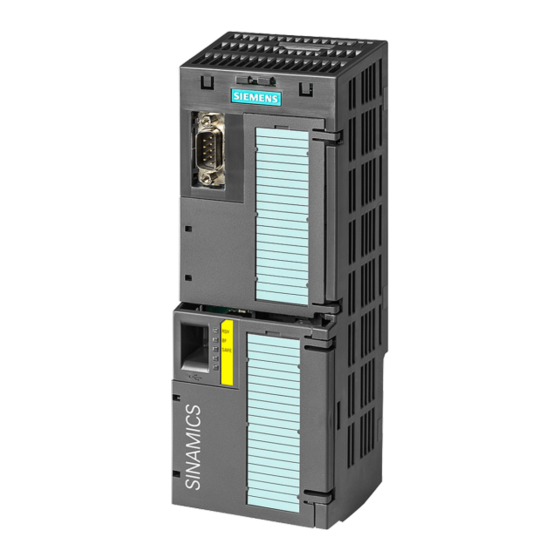
PM240 Power Modules Overview The PM240 Power Modules belong to the modular family of SINAMICS G120 inverters. A modular inverter comprises Control Unit and Power Module. The PM240 Power Modules are designed for line voltages of 3 AC 380 V … 480 V. -
Page 20: Component Specification According To Ul
You can find proof of the certification on the Internet UL certificates (http://www.ul.com) under "Tools / Online Certifications Directory" by entering the file number or the "Name". The UL file number for the Power Modules of the SINAMICS G120 product family is: ● E121068 for FSA, FSB and FSC ●... -
Page 21: Installing/Mounting
Inverters for systems in the United States / Canada (UL/cUL) ● For configurations in conformance with UL/cUL, use the UL/cUL-approved fuses, Class J or Siemens 3NE1 semiconductor fuses, which are specified in this manual. Permissible fuse types and characteristic values: Technical data (Page 61). -
Page 22: Emc-Compliant Installation Of A Plant Or Machine
Installing/mounting 4.2 EMC-compliant installation of a plant or machine EMC-compliant installation of a plant or machine 4.2.1 Control cabinet The inverter is designed for operation in industrial environments where high-level electromagnetic fields are to be expected. Reliable and disturbance-free operation of the inverter is only ensured if the inverter is installed in compliance with EMC regulations. - Page 23 Installing/mounting 4.2 EMC-compliant installation of a plant or machine ● Electromagnetically uncouple the zones from each other by means of one of the following actions: – Side clearance ≥ 25 cm – Separate metal enclosure – Large-area partition plates ● Assign the various devices to zones in the control cabinet. ●...
- Page 24 Image 4-2 Grounding and high-frequency equipotential bonding measures in the control cabinet and in the plant/system Further information Additional information about EMC-compliant installation is available in the Internet: EMC installation guideline (http://support.automation.siemens.com/WW/view/en/60612658) Power Modules PM240 Hardware Installation Manual, 07/2016, A5E36985441C AA...
-
Page 25: Cables
Installing/mounting 4.2 EMC-compliant installation of a plant or machine 4.2.2 Cables Cables with a high level of interference and cables with a low level of interference are connected to the inverter: ● Cables with a high level of interference: – Cable between the line filter and inverter –... - Page 26 Installing/mounting 4.2 EMC-compliant installation of a plant or machine Image 4-3 Routing inverter cables inside and outside a control cabinet Routing cables outside the control cabinet ● Maintain a minimum clearance of 25 cm between cables with a high level of interference and cables with a low level of interference.
-
Page 27: Electromechanical Components
Installing/mounting 4.2 EMC-compliant installation of a plant or machine Requirements relating to shielded cables ● Use cables with finely-stranded, braided shields. ● Connect the shield to at least one end of the cable. Image 4-4 Examples for EMC-compliant shield support ●... -
Page 28: Power Losses And Air Cooling Requirements
Installing/mounting 4.3 Power losses and air cooling requirements Power losses and air cooling requirements Cooling requirements Depending on the power loss of the individual components, the control cabinet will require a cooling airflow to prevent the components from overheating. Formula for calculating the cooling airflow: Total of the power losses of the individual components. - Page 29 Installing/mounting 4.3 Power losses and air cooling requirements Image 4-5 Air barriers for avoiding cooling air short circuits Power Modules PM240 Hardware Installation Manual, 07/2016, A5E36985441C AA...
-
Page 30: Mounting The Power Modules
Installing/mounting 4.4 Mounting the Power Modules Mounting the Power Modules Protection against the spread of fire The device may be operated only in closed housings or in control cabinets with protective covers that are closed, and when all of the protective devices are used. The installation of the device in a metal control cabinet or the protection with another equivalent measure must prevent the spread of fire and emissions outside the control cabinet. -
Page 31: Dimension Drawings And Drilling Dimensions, Fsa
Installing/mounting 4.4 Mounting the Power Modules 4.4.1 Dimension drawings and drilling dimensions, FSA ... FSF The following dimensioned drawings and drilling patterns are not to scale. Table 4- 1 Installation dimensions without Control Unit (CU) [mm] Frame size Width Height Depth without shield plate with shield plate... - Page 32 Installing/mounting 4.4 Mounting the Power Modules Table 4- 2 Depth with Control Unit and operator panel Depth (mm) with ... CU230P-2 CU240B/E-2 CU250S-2 … Control Unit: + 59 + 41 + 62 ... Control Unit and blanking cover / BOP-2: + 70 + 52 + 73...
-
Page 33: Dimensioned Drawings And Drilling Dimensions, Fsgx
Installing/mounting 4.4 Mounting the Power Modules 4.4.2 Dimensioned drawings and drilling dimensions, FSGX Mount the Power Module with the following clearances to other devices: ● Top: 250 mm ● Bottom: 150 mm ● Lateral: no clearance required for thermal reasons. Fasten the Power Module with six M8 screws with a tightening torque of 13 Nm. -
Page 34: Additional Components
Installing/mounting 4.5 Additional components Additional components Depending on the particular application, additional components may be required for your system. Information about additional components is provided in the following Sections: Connection overview (Page 42) Optional accessories (Page 82). Power Modules PM240 Hardware Installation Manual, 07/2016, A5E36985441C AA... -
Page 35: Connecting-Up
To protect against indirectly touching part of the motor circuit of an inverter and to automatically shut down in the case of a fault according to DIN EN 60364-4-41 (VDE 0100- 410). (http://support.automation.siemens.com/WW/view/en/103474630) Power Modules PM240 Hardware Installation Manual, 07/2016, A5E36985441C AA... - Page 36 Connecting-up WARNING Danger to life due to fire or electric shock when using unsuitable residual current protection devices The inverter can cause a current to flow in the protective conductor. This current can cause the residual current device (RCD) or residual current monitoring (RCM) to incorrectly trip (nuisance trip).
- Page 37 Connecting-up Image 5-1 MRCD ● A dedicated RCD is used for every inverter. ● The motor cables are shorter than 50 m (164 ft) shielded, or 100 m (328 ft) unshielded. Length of motor cable (Page 43) Power Modules PM240 Hardware Installation Manual, 07/2016, A5E36985441C AA...
-
Page 38: Permissible Line Supplies
Connecting-up 5.1 Permissible line supplies Permissible line supplies Note Restrictions for installation altitudes above 2000 m Above an installation altitude of 2000 m, the permissible line supplies are restricted. Restrictions for special ambient conditions (Page 71) Note Line requirement The machine manufacturer must ensure that in operation the voltage drop between the transformer input terminals and the inverter when operated with its rated values is less than The inverter is designed for the following power distribution systems according to IEC 60364- 1 (2005). -
Page 39: Tt Line System
Connecting-up 5.1 Permissible line supplies 5.1.2 TT line system In a TT line system, the transformer grounding and the installation grounding are independent of one another. There are TT line supplies where the neutral conductor N is either transferred – or not. -
Page 40: Protective Conductor
Connecting-up 5.1 Permissible line supplies 5.1.4 Protective conductor WARNING Danger to life caused by high leakage currents for an interrupted protective conductor The drive components conduct a high leakage current via the protective conductor. Touching conductive parts when the protective conductor is interrupted can result in death or serious injury. - Page 41 Connecting-up 5.1 Permissible line supplies ① Additional requirements placed on the protective conductor ● For permanent connection, the protective conductor must fulfill at least one of the following conditions: – The protective conductor is routed so that it is protected against damage along its complete length.
-
Page 42: Connecting The Line And Motor Cable At The Inverter
Connecting-up 5.2 Connecting the line and motor cable at the inverter Connecting the line and motor cable at the inverter 5.2.1 Connection overview Note Base components Up to frame size FSC, you can install reactors, filters and braking resistors as base components. -
Page 43: Connecting Inverters In Compliance With Emc Regulations
Connecting-up 5.2 Connecting the line and motor cable at the inverter 5.2.2 Connecting inverters in compliance with EMC regulations EMC-compliant wiring for connecting the line supply and motor with shield plate. ① Line supply cable - unshielded • Strain relief using a cable clamp ②... - Page 44 Connecting-up 5.2 Connecting the line and motor cable at the inverter When using the inverter in the first environment, also carefully observe the information in Section Inverter applications (Page 75) Table 5- 1 Permissible length of motor connecting cables Frame Inverter with filter, category Inverter without filter size...
-
Page 45: Inverter Terminals
Connecting-up 5.2 Connecting the line and motor cable at the inverter 5.2.4 Inverter terminals Table 5- 2 Connection type, cable cross sections and tightening torques Inverters Connection Cross-section and tightening torque Strip lengths Metric Imperial Line, motor cable, DC Terminal 1.0 ... -
Page 46: Establishing Connections
Connecting-up 5.2 Connecting the line and motor cable at the inverter 5.2.5 Establishing connections Procedure Proceed as follows to establish the connections: 1. Ensure that the device is in a no-voltage condition and the DC link is discharged. 2. Establish the connections as described in the following sections. This means that you have established the connections. -
Page 47: Connections Fsgx
Connecting-up 5.2 Connecting the line and motor cable at the inverter Connection rules for Power Modules, FSD … FSF Connect the line and motor cables to the inverter using ring-shaped cable lugs which are in conformance with DIN 462. A suitable ring-shaped cable lug is shown at the left in the diagram, and an unsuitable standard cable lug is shown at the right. - Page 48 Connecting-up 5.2 Connecting the line and motor cable at the inverter 7. After you have established the connections, re-attach the inverter front cover. External 24 V supply An external power supply with the following specifications is required to operate the FSGX Power Module.
-
Page 49: Connecting The Motor To The Inverter In A Star Or Delta Connection
Connecting-up 5.3 Connecting the motor to the inverter in a star or delta connection Connecting the motor to the inverter in a star or delta connection Standard induction motors with a rated power of approximately ≤ 3 kW are normally connected in a star/delta connection (Y/Δ) at 400 V/230 V. -
Page 51: Service And Maintenance
WARNING Danger due to incorrect repair Repairs may only be carried out by Siemens Service, by repair centers authorized by Siemens or by authorized personnel who are thoroughly acquainted with all the warnings and operating procedures contained in this manual. -
Page 52: Maintenance
Note The actual maintenance intervals depend on the installation and operating conditions. Siemens offers its customers support in the form of service contracts. For further information, contact your Siemens regional office or sales office. Power Modules PM240... -
Page 53: Commissioning After A Long Storage Time
Service and maintenance 6.2 Commissioning after a long storage time Commissioning after a long storage time If the inverter was not operational for a longer period of time, it is possible that you must form the DC link capacitors before switching on. Form the DC link capacitors in the following cases: ●... -
Page 54: Replace The Fan
Service and maintenance 6.3 Replace the fan Replace the fan Service life of the fan The average service life of the fan is 40,000 hours. In practice, however, the service life may deviate from this value. Especially a dusty environment can block up the fan. The fan must be replaced in good time to ensure that the inverter is ready for operation. - Page 55 Service and maintenance 6.3 Replace the fan Fan replacement, frame sizes FSB, FSC Procedure 1. Switch-off the inverter. 2. Remove the Control Unit from the inverter. 3. Disconnect all the cables from the Power Module. 4. Place the Power Module on a clean and secure surface with its front side down. 5.
- Page 56 Service and maintenance 6.3 Replace the fan Fan replacement, frame sizes FSD and FSE: Procedure 1. Switch the inverter off. 2. Disconnect all the cables from the Power Module. ① 3. Release the fan cover catches ② ③ 4. Release and remove the fan cover ④...
- Page 57 Service and maintenance 6.3 Replace the fan Fan replacement, frame size FSF Procedure 1. Switch-off the inverter. 2. Disconnect all the cables from the Power Module. ① ② 3. Release the four screws and remove the fan cover plate ③ 4.
- Page 58 Service and maintenance 6.3 Replace the fan Fan replacement, frame size FSGX Procedure 1. Switch off the inverter. 2. Remove the inverter front cover. Connections FSGX (Page 47). 3. Replace the fan as shown in the diagram. Install the new fan in the reverse sequence. Fan relay and fan fuses The fan is controlled using a relay in the inverter.
-
Page 59: Replacing The Fsgx Power Block
Service and maintenance 6.4 Replacing the FSGX power block Replacing the FSGX power block Replacing the power block, frame size FSGX Procedure 1. Switch the inverter off. 2. Remove the inverter front cover. Connections FSGX (Page 47). ① 3. Release the connection to the motor output area (3 screws on the right-hand side). ②... - Page 60 Service and maintenance 6.4 Replacing the FSGX power block 12.Release the two mounting screws for the fan and attach the tool to uninstall the Power ⑩ Block at this location 13.You can now slide out the Power Block from the inverter towards the front. To do this, use the crane lifting lugs at the Power Block.
-
Page 61: Technical Data
Technical data Permissible power range of the motors For the Power Modules, induction motors are permissible in the range from 25 % … 150 % of the inverter power without any restrictions. Note Motors for inverter operation Only use motors that are suitable for operation with inverters with a DC link. Ambient conditions Property Version... - Page 62 Technical data 7.2 Overload capability of the inverter Property Version Ambient conditions in operation Installation altitude Up to 1000 m above sea level without derating, > 1000 m Restrictions for special ambient conditions (Page 71) Climatic ambient conditions Temperature range •...
-
Page 63: Overload Capability Of The Inverter
Low Overload. We recommend the "SIZER" engineering software to select the inverter. You will find additional information about SIZER on the Internet: Download SIZER (http://support.automation.siemens.com/WW/view/en/10804987/130000). Load cycles and typical applications: "Low Overload" load cycle "High Overload" load cycle The "Low Overload"... -
Page 64: Cable Cross-Sections And Tightening Torques
Technical data 7.3 Cable cross-sections and tightening torques Typical inverter load cycles Image 7-1 "High Overload" and "Low Overload" load cycles Cable cross-sections and tightening torques Table 7- 1 Connection type, cable cross sections and tightening torques Inverters Connection Cross-section and tightening torque Strip lengths Metric... -
Page 65: General Data
Technical data 7.4 General data General data Property Version Line voltage 3-phase 380 … 480 VAC ± 10% Output voltage 3-phase 0 VAC … input voltage x 0.95 (max.) Input frequency 50 Hz … 60 Hz, ± 3 Hz Output frequency 0 Hz …... - Page 66 2.0 A 2.5 A HO base load output current 1.3 A 1.7 A 2.2 A Fuse according to UL (from SIEMENS) 3NE1813-0, 16 A 3NE1813-0, 16 A 3NE1813-0, 16 A Fuse according to UL (Class J, K-1 or K-5) 10 A...
- Page 67 23.7 A 32.7 A HO base load output current 13.2 A 19 A 26 A Fuse according to UL (from SIEMENS) 3NE1814-0, 20 A 3NE1814-0, 20 A 3NE1803-0, 35 A Fuse according to UL (Class J, K-1 or K-5) 20 A...
- Page 68 HO base load input current 73 A 90 A HO base load output current 60 A 75 A Fuse according to UL (SIEMENS) 3NE1021-0 3NE1022-0 Fuse according to UL (Class J) 100 A / 600 V 125 A / 600 V Power losses without filter 0.99 kW...
- Page 69 HO base load input current 205 A 235 A HO base load output current 178 A 205 A Fuse according to UL (SIEMENS) 3NE1227-0 3NE1230-0 Fuse according to UL (Class J) 300 A, 600 V 400 A, 600 V Power loss 2.4 kW...
-
Page 70: Current Derating Depending On The Pulse Frequency
Technical data 7.5 Specific technical data 7.5.1 Current derating depending on the pulse frequency MLFB LO base Output base-load current for a pulse frequency of load 2 kHz 4 kHz 6 kHz 8 kHz 10 kHz 12 kHz 14 kHz 16 kHz 6SL3224-…... -
Page 71: Restrictions For Special Ambient Conditions
Technical data 7.6 Restrictions for special ambient conditions Restrictions for special ambient conditions Maximum current at low speeds NOTICE Negative impact on the inverter service life. At low speeds, the inverter can only briefly supply the base load output current. It is especially important to note that DC voltage operation (continuous operation at 0 Hz) is not permissible. - Page 72 Technical data 7.6 Restrictions for special ambient conditions The Control Unit and operator panel can restrict the maximum permissible operating ambient temperature of the Power Module. Current derating or temperature reduction depending on the installation altitude Above 1000 m above sea level you must reduce the inverter output current or the permissible operating ambient temperature as a result of the lower cooling capability of the air.
-
Page 73: Electromagnetic Compatibility Of Variable-Speed Drives
Technical data 7.7 Electromagnetic compatibility of variable-speed drives Electromagnetic compatibility of variable-speed drives EMC (electromagnetic compatibility) means that the devices function satisfactorily without interfering with other devices and without being disrupted by other devices. This is true when the emitted interference (emission level) and the interference immunity are matched with each other. - Page 74 Technical data 7.7 Electromagnetic compatibility of variable-speed drives Categories IEC/EN 61800-3 makes a distinction between four drive system categories: ● Category C1: Drive systems for rated voltages < 1000 V for unrestricted use in the first environment ● Category C2: Stationary drive systems for rated voltages <...
-
Page 75: Inverter Applications
- and are not operated in the general public domain. Carefully observe the information in the "EMC installation guideline" Configuration Manual under EMC installation guideline (http://support.automation.siemens.com/WW/view/en/60612658) for EMC-compliant installation. The Power Modules described here are intended for operation in the first and second environments. - Page 76 When connected to IT line supplies, only filtered inverters are permissible. Use external filters without capacitors with respect to ground to limit symmetrical interference emission. When necessary, contact one of our Solution Partners (https://www.automation.siemens.com/solutionpartner/partnerfinder/Home/Index?country=D E&program=1&technology=19&lang=en). Power Modules PM240 Hardware Installation Manual, 07/2016, A5E36985441C AA...
-
Page 77: Operation In The First Environment
Note Line reactor Contact one of our Solution Partners for a line reactor. Solution Partners (https://www.automation.siemens.com/solutionpartner/partnerfinder/Home/Index?coun try=DE&program=1&technology=19&lang=en). FSD Power Modules: A line reactor is not required. – Short-circuit power S at the connection point of the customer's system to the public grid, is not greater or is equal to the value according to the following formula: ≥... -
Page 78: Radio Interference Suppression Filters According To Cispr 11/En 55011 Class B
Technical data 7.7 Electromagnetic compatibility of variable-speed drives Example: FSD inverter, 400 V, input current, 72 A: ≥ 120 ∙ √3 ∙ 400 V ∙ 72 A This corresponds to a low-voltage transformer with an apparent power rating of approximately 300 kVA … 400 kVA with 4 % … 6 % U If these preconditions do not apply, then the installation company or company operating the device must obtain authorization from the grid operator to connect the device regarding the harmonic currents. -
Page 79: Emc Limit Values In South Korea
Technical data 7.7 Electromagnetic compatibility of variable-speed drives 7.7.4 EMC limit values in South Korea The EMC limit values to be observed for Korea correspond to the limit values of the EMC product standard for variable-speed electric drives EN 61800-3 of category C2 or the limit value class A, Group 1 to KN11. - Page 80 Technical data 7.7 Electromagnetic compatibility of variable-speed drives Power Modules PM240 Hardware Installation Manual, 07/2016, A5E36985441C AA...
-
Page 81: Spare Parts And Accessories
Spare parts and accessories Product maintenance Inverter components are being continuously developed within the scope of product update. The product update includes, for example, measures to increase the ruggedness or hardware changes, which are necessary as components are being discontinued. These further developments are "spare parts-compatible"... -
Page 82: Optional Accessories
Spare parts and accessories 8.3 Optional accessories Optional accessories Which components are available? ● Mounting frames for PT Power Modules - frame sizes FSA … FSC ● Line reactor ● Line filter ● Output reactors ● Sine-wave filters ● Braking choppers - for FSGX, for FSA … FSF integrated in the Power Module ●... - Page 83 Spare parts and accessories 8.3 Optional accessories Installing two base components Connection components Connection overview for the electrical components Connection overview (Page 42). Power Modules PM240 Hardware Installation Manual, 07/2016, A5E36985441C AA...
-
Page 84: Line Reactor
Spare parts and accessories 8.3 Optional accessories 8.3.2 Line reactor A line reactor protects the inverter when connected to dirty line supplies. A line reactor supports the overvoltage protection, smooths the harmonics in the line supply and buffers commutation dips. The line reactors for Power Modules, frame sizes FSA …... - Page 85 Spare parts and accessories 8.3 Optional accessories Dimensions and drilling patterns Image 8-2 Line reactors Power Modules PM240 Hardware Installation Manual, 07/2016, A5E36985441C AA...
- Page 86 Spare parts and accessories 8.3 Optional accessories Table 8- 1 Dimensions and weights Article number Overall dimensions (mm) Drilling dimensions (mm) Fixing/torque Weight (Nm) (kg) For FSA … FSD 6SE6400-3CC00-2AD3 75.5 4 x M4 / 2.5 6SE6400-3CC00-4AD3 6SE6400-3CC00-6AD3 6SL3203-0CD21-0AA0 4 x M4 / 2.5 6SL3203-0CD21-4AA0 6SL3203-0CD22-2AA0 4 x M5 / 3...
- Page 87 Spare parts and accessories 8.3 Optional accessories Article number Induct- Power loss Connection (mm Degree ance (mH) (W) for of pro- Line supply Power Module tection 50 / 60 Hz 6SL3000-0CE32-8AA0 62 μH 210 / 250 M10 cable lug M8 studs IP00 6SL3000-0CE33-3AA0 52 μH...
-
Page 88: Line Filter
Spare parts and accessories 8.3 Optional accessories 8.3.3 Line filter With a line filter, the inverter can achieve a higher radio interference class. The line filters integrated in the inverter correspond to Category C2 according to EN 61800-3. External filters are available for Category C2 or C1 according to EN 61800-3. Details are provided in the following tables. - Page 89 Spare parts and accessories 8.3 Optional accessories Table 8- 4 Dimensions and weights Article number Overall dimensions Drilling dimensions (mm) Weight (mm) (kg) Fixing/torque (Nm) 6SE6400-2FA00-6AD0 43.5 205.5 4 x M4 / 2.5 6SE6400-2FB00-6AD0 6SL3203-0BE21-6SA0 4 x M4 / 2.5 6SL3203-0BD23-8SA0 4 x M5 / 3 6SL3203-0BE32-5AA0...
-
Page 90: Output Reactor
Spare parts and accessories 8.3 Optional accessories 8.3.4 Output reactor Mounting position Clearances to other devices Keep shaded areas free of any devices and components. Image 8-5 Minimum clearances of the output reactor to other devices, space-saving mounting examples When using the output reactor it is not permissible that the output frequency exceeds 150 Hz It is not permissible that the pulse frequency exceeds 4 kHz Power Modules PM240 Hardware Installation Manual, 07/2016, A5E36985441C AA... - Page 91 Spare parts and accessories 8.3 Optional accessories Dimensions and drilling patterns Image 8-6 Output reactors as base component for frame sizes FSA … FSC Image 8-7 Standalone output reactors for frame sizes FSD … FSGX Power Modules PM240 Hardware Installation Manual, 07/2016, A5E36985441C AA...
- Page 92 Spare parts and accessories 8.3 Optional accessories Table 8- 7 Dimensions and weights Article number Overall dimensions Drilling dimensions Fixing/torque Weight (mm) (mm) (Nm) (kg) Reactors that can be mounted as base component 6SE6400-3TC00-4AD2 75.5 4 x M4 / 2.5 6SL3202-0AE21-0CA0 4 x M4 / 2.5 6SL3202-0AJ23-2CA0...
- Page 93 Spare parts and accessories 8.3 Optional accessories Article number Connection (mm Power gree of loss (W) Line supply Power Module protec- tion 6SL3000-2BE32-1AA0 M10 cable lug M8 screw IP00 6SL3000-2BE32-6AA0 M10 cable lug M8 screw IP00 6SL3000-2BE33-2AA0 M10 cable lug M8 screw IP00 6SL3000-2BE33-8AA0...
-
Page 94: Sine-Wave Filter
Spare parts and accessories 8.3 Optional accessories 8.3.5 Sine-wave filter The sine-wave filter at the inverter output limits the voltage rate-of-rise and the peak voltages at the motor winding. The maximum permissible length of motor feeder cables is increased to 300 m. The following applies when using a sine-wave filter: ●... - Page 95 Spare parts and accessories 8.3 Optional accessories Sine-wave filter - stand alone, frame size 1 Sine-wave filter Overall dimensions Drilling dimensions Fixing/torque Weight (mm) (mm) (Nm) (kg) 6SL3202-0AE24-6SA0 90.5 4 x M6 / 7 6SL3202-0AE26-2SA0 90.5 4 x M6 / 7 6SL3202-0AE28-8SA0 100.5 4 x M8 / 13...
- Page 96 Spare parts and accessories 8.3 Optional accessories Sine-wave filter - stand alone, frame size 2 Sine-wave filter Overall dimensions Drilling dimensions Fixing/torque Weight (mm) (mm) (Nm) (kg) 6SL3000-2CE32-3AA0 6 x M10 / 20 6SL3000-2CE32-8AA0 6 x M10 / 20 6SL3000-2CE33-3AA0 6 x M10 / 20 6SL3000-2CE34-1AA0 6 x M10 / 20...
- Page 97 Spare parts and accessories 8.3 Optional accessories Article number Connection Degree loss 1) of pro- Power Module Motor tection 6SL3202-0AE23-3SA0 Integrated 500 mm Screw terminals 6 mm IP20 6SL3202-0AE24-6SA0 Screw terminals 25 … 50 mm IP20 6SL3202-0AE26-2SA0 Screw terminals 25 … 50 mm IP20 6SL3202-0AE28-8SA0 Screw terminals 25 …...
-
Page 98: Braking Module - Only Fsgx
Spare parts and accessories 8.3 Optional accessories 8.3.6 Braking Module - only FSGX The Braking Module controls the external braking resistor. For frame sizes FSA … FSF, it is integrated in the Power Module. The Braking Module can be ordered as accessory for the power Module FSGX. Article number: 6SL33-001AE32-5AA0). -
Page 99: Braking Module - Settings And Connections
Spare parts and accessories 8.3 Optional accessories 8.3.6.1 Braking Module - settings and connections Threshold switch Using the threshold switch, you set at which DC link voltage the braking resistor is switched in. It is only permissible that you change the setting of the threshold switch in the voltage- free state. -
Page 100: Braking Resistor
Spare parts and accessories 8.3 Optional accessories 8.3.7 Braking resistor The braking resistor enables loads with a large moment of inertia to be braked quickly. During braking of the motor and the load, excess energy is fed back to the converter. This causes the voltage to rise in the DC link. - Page 101 Spare parts and accessories 8.3 Optional accessories Image 8-10 Minimum clearances for the braking resistor when mounting on a flat surface and for wall/panel mounting Keep shaded areas free of any devices and components. Dimensions, drilling pattern und weights Image 8-11 Drilling and envelope dimensions Power Modules PM240 Hardware Installation Manual, 07/2016, A5E36985441C AA...
- Page 102 Spare parts and accessories 8.3 Optional accessories Table 8- 12 Dimensions and weights Article No. Overall dimensions (mm) Drilling dimensions (mm) Weight (kg) Mounting 6SE6400-4BD11-0AA0 43.5 M4 / 3 Nm 6SL3201-0BE12-0AA0 43.5 M4 / 3 Nm 6SE6400-4BD16-5CA0 M4 / 3 Nm 6SE6400-4BD21-2DA0 M4 / 3 Nm 6SE6400-4BD22-2EA0...
- Page 103 Spare parts and accessories 8.3 Optional accessories Table 8- 14 Assignment tables Article number Power Module Article number Frame size 6SE6400-4BD11-0AA0 6SL3224-0BE13-7UA0 6SL3224-0BE15-5UA0 6SL3224-0BE17-5UA0 6SL3224-0BE21-1UA0 6SL3224-0BE21-5UA0 6SL3201-0BE12-0AA0 6SL3224-0BE22-2 . A0 6SL3224-0BE23-0 . A0 6SL3224-0BE24-0 . A0 6SE6400-4BD16-5CA0 6SL3224-0BE25-5 . A0 6SL3224-0BE27-5 .
-
Page 104: Connect The Temperature Contact Of The Braking Resistor
Spare parts and accessories 8.3 Optional accessories 8.3.7.1 Connect the temperature contact of the braking resistor Monitoring the temperature of the braking resistor Procedure Proceed as follows to monitor the braking resistor temperature: 1. Connect the temperature monitoring system of the braking resistor (terminals T1 and T2 on the braking resistor) to a free digital input at the Control Unit of the inverter. -
Page 105: Mounting And Connecting The Brake Relay
Spare parts and accessories 8.3 Optional accessories Note Brake Relay and Safe Brake Relay The Brake Relay and the Safe Brake Relay do not differ from each other in the installation and the connection to the inverter. Connection to the inverter To ensure that you have the correct cable for connecting the Brake Relay irrespective of the inverter size, you are supplied with two preassembled cables with different lengths. -
Page 106: Mounting And Connecting The Safe Brake Relay
Spare parts and accessories 8.3 Optional accessories 8.3.8.2 Mounting and connecting the Safe Brake Relay The Brake Relay must be connected to the protective conductor if the motor brake is supplied from a PELV circuit. 8.3.8.3 Technical data of the brake relay? Brake Relay Safe Brake Relay 6SL3252-0BB00-0AA0... -
Page 107: Mounting And Connecting The Brake Relay
Spare parts and accessories 8.3 Optional accessories 8.3.8.4 Mounting and connecting the brake relay Installing the Brake Relay If you use the optional shield plate, install the Brake Relay on the shield plate of the Power Module. If you do not use the shield plate, install the Brake Relay as close as possible to the Power Module. -
Page 108: For Standard Rail Mounting
The installation grid for DIN mounting rails is 115 (± 1) mm. Mounting the DIN mounting rail adapter (DRMK) You can find the mounting instructions for the DIN mounting rail adapter in the Internet at: (https://support.industry.siemens.com/cs/ww/en/view/23622394) 8.3.10 Shield connection kit The shield connection kit is used to connect the shield of the control and motor cable in an EMC-compliant fashion. -
Page 109: Appendix
Manuals and technical support A.1.1 Overview of the manuals Manuals with additional information that can be downloaded: ● PM240 Power Modules (https://support.industry.siemens.com/cs/ww/de/view/52593268/en) Installing Power Modules, reactors and filters. Technical specifications, maintenance (this manual) ● CU230P-2 Compact Operating Instructions (https://support.industry.siemens.com/cs/ww/en/view/109477360) Commissioning the inverter ●... - Page 110 Installing, commissioning and maintaining the inverter. Advanced commissioning ● EMC installation guideline (http://support.automation.siemens.com/WW/view/en/60612658) EMC-compliant control cabinet design, potential equalization and cable routing ● CU230P-2 List Manual (https://support.industry.siemens.com/cs/ww/en/view/109477248) Parameter list, alarms and faults. Graphic function diagrams ● CU240E, CU240S List Manual (https://support.industry.siemens.com/cs/ww/de/view/27864391/en) Parameter list, alarms and faults.
-
Page 111: Configuring Support
Catalog Ordering data and technical information for SINAMICS G inverters. Catalog D31 for download or online catalog (Industry Mall): All about SINAMICS G120 (www.siemens.com/sinamics-g120) SIZER The configuration tool for SINAMICS, MICROMASTER and DYNAVERT T drives, motor starters, as well as SINUMERIK, SIMOTION controllers and SIMATIC technology... -
Page 112: Product Support
Appendix A.1 Manuals and technical support EMC installation guideline (http://support.automation.siemens.com/WW/view/en/60612658) Safety Integrated for novices technical overview Application examples for SINAMICS G drives with Safety Integrated Safety Integrated for novices (https://support.industry.siemens.com/cs/ww/en/view/80561520) A.1.3 Product Support Additional information about the product and more is available in the Internet: Product support (http://www.siemens.com/automation/service&support). -
Page 113: Disposal
Disposal Protecting the environment and preserving its resources are corporate goals of the highest priority for Siemens. Our worldwide environmental management system according to ISO 14001 ensures compliance with legislation and sets high standards in this regard. Environmentally friendly design, technical safety and health protection are always firm goals, even at the product development stage. -
Page 114: Directives And Standards
Appendix A.3 Directives and standards Directives and standards Relevant directives and standards The following directives and standards are relevant for the inverters: European Low Voltage Directive The inverters fulfil the requirements stipulated in the Low-Voltage Directive 2014/35/EU, if they are covered by the application area of this directive. European Machinery Directive The inverters fulfil the requirements stipulated in the Machinery Directive 2006/42//EU, if they are covered by the application area of this directive. - Page 115 Specification for semiconductor process equipment voltage drop immunity The inverters comply with the requirements of standard SEMI F47-0706. Quality systems Siemens AG employs a quality management system that meets the requirements of ISO 9001 and ISO 14001. Certificates for download You can find the EC declaration of conformity in the Internet at: Declaration of conformity (https://support.industry.siemens.com/cs/ww/en/view/58275445)
-
Page 116: Abbreviations
Appendix A.4 Abbreviations Abbreviations Abbreviation State Alternating current Communauté Européenne Control Unit Direct current Digital input DIP switch Digital output Equivalent circuit diagram European Economic Community ELCB Earth leakage circuit breaker Electromagnetic compatibility (EMC) Electromagnetic interference FS… Frame size ... Getting Started Guide High overload Input/Output... -
Page 117: Index
Index 87 Hz characteristic, 49, 49 Electrical installation, 35 EMC, 22, 22 Adapter for mounting on DIN rails, 108 Air barrier, 28 Field weakening, 49 Function Manual, 109 Base components, 82 Base load, 63 Getting Started, 109 Base load input current, 63 Base load output current, 63 Base load power, 63 Brake Relay, 104... - Page 118 Index Maintenance Cleaning, 52 Dirt, 52 Pollution, 52 Terminals, 52 Ventilation, 52 Neutral conductor, 38 Operating Instructions, 109 Overvoltage protection, 84 Power distribution systems, 38 Power range of the motors, 19 Protective conductor, 38 Questions, 112 Radio interference class, 88 Safe Brake Relay, 104 Safety notes Electrical installation, 35...