Table of Contents
Advertisement
Use
CC1N7451en
20.11.2017
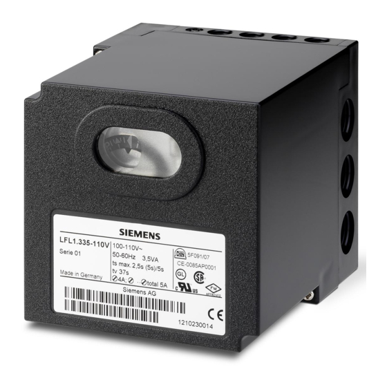
Burner Controls
Burner controls
For gas, oil or dual-fuel forced draft burners of medium to high capacity
For multistage or modulating burners in intermittent operation
With checked air damper control
– with UV detectors QRA2 / QRA4 / QRA10
– and ionization probe
The LFL1... and this Data Sheet are intended for use by OEMs which integrate the
burner controls in their products!
Control and supervision of forced draft burners of direct spark flame or interrupted
pilot construction
For medium to high capacity
For intermittent operation (at least one controlled shutdown every 24 hours)
For universal use with multistage or modulating burners
For use with stationary air heaters (WLE)
For use with dual-fuel burners
Type-tested and approved in accordance with DIN EN 298
The flame supervision is ensured via a flame detector QRA2 / QRA4 / QRA10 or
ionization probe. The difference between 01 series and 02 series is the duration of the
safety time for the pilot burner of burners equipped with pilot gas valves.
For atmospheric burners of high capacity, use the LFL1.638.
Building Technologies Division
7
451
LFL1...
Advertisement
Table of Contents

Related Manuals for Siemens LFL1.133


Summary of Contents for Siemens LFL1.133
- Page 1 Burner Controls LFL1... Burner controls For gas, oil or dual-fuel forced draft burners of medium to high capacity For multistage or modulating burners in intermittent operation With checked air damper control Flame supervision – with UV detectors QRA2 / QRA4 / QRA10 –...
- Page 2 Supplementary documentation Type of documentation Product type Documentation number Data Sheet LGK16 (burner controls for continuous N7785 operation) Warning notes To avoid injury to persons, damage to property or the environment, the following warning notes must be observed! Do not open, interfere with or modify the unit! ...
- Page 3 Application notes For use in applications in dual-fuel burners or oil burners, the oil supply must be equipped with two shutoff valves connected in series. Observe the following: EN 298:2012, Section 7.101.3.3 Prepurge time for oil burner control systems and the corresponding application standards.
- Page 4 Engineering notes Install switches, fuses, earthing, etc., in compliance with local regulations Decisive for the connection of the valves and other plant components is the plant diagram provided by the burner manufacturer 13 12 14 22 23 QRA... bv...
- Page 5 Certified complete with plug-in base and flame detector: Type reference ● ● ● ● ● ● ● LFL1.122 ● ● ● ● ● LFL1.133 ● ● ● ● ● ● ● LFL1.322 ● ● ● ● ● ● LFL1.333 ●...
- Page 6 Life cycle Burner controls has a designed lifetime* of 250,000 burner startup cycles which, under normal operating conditions in heating mode, correspond to approx. 10 years of usage (starting from the production date given on the type field). This lifetime is based on the endurance tests in the standard EN 298. A summary of the conditions has been published by the European Control Manufacturers Association (Afecor) (www.afecor.org).
- Page 7 Flash steam Incl. ²) Large generators generators stationary atmospheric air heaters burners Type LFL1.122 ¹) LFL1.133 ¹) LFL1.322 ¹) LFL1.333 ¹) LFL1.335 ¹) LFL1.622 ¹) LFL1.635 ¹) LFL1.638 02 series 02 series 02 series 02 series 01 series 02 series...
- Page 8 Accessories (to be ordered separately) UV flame detectors QRA2... Flame detectors See Data Sheet N7712 UV flame detector QRA4... See Data Sheet N7711 UV flame detector QRA10... See Data Sheet N7712 Ionization probe to be supplied by thirds Plug-in base AGM410490550 with Pg11 thread for cable Connection accessories entry glands.
- Page 9 Accessories (to be ordered separately) Actuator SQN72... Actuators See Data Sheet N7802 Actuator SQN70... / SQN71... / SQN74... / SQN75... See Data Sheet N7804 Actuator SQN9... See Data Sheet N7806 Actuator SQM40... / SQM41 See Data Sheet N7817 Actuator SQM5... See Data Sheet N7815 9/25 Building Technologies Division...
- Page 10 Technical data General unit data Mains voltage AC 230 V –15 / +10 % LFL1... AC 100 V –15%...AC 110 V +10% Mains frequency 50...60 Hz ±6 % Unit fuse (built-in) T6.3H250V to DIN EN 60 127 Primary fuse (external) max.
- Page 11 Technical data (cont'd) Flame supervision with Voltage at the ionization probe ionization probe - Operation AC 330 V ±10 % - Test AC 380 V ±10 % Short-circuit current max. 0.5 mA Recommended range of measuring 0...50 µA instrument Perm. length of detector cable - Normal cable, laid separately ²) max.
- Page 12 Function 2-stage direct spark flame burner Legend BV... Fuel valve Flame signal amplifier Air damper Load controller M... Fan or burner motor Control thermostat or pressurestat Modulating fuel valve Ignition transformer t4 t5 Pilot gas valve 100% Start command by «R» min.
- Page 13 Function (cont'd) General The following features enable the LFL1... to offer a high level of additional safety: Detector and extraneous light test are resumed immediately on completion of the afterburn time «t13». Fuel valves that are not closed, or not fully closed, immediately initiate lockout on completion of the afterburn time «t13».
- Page 14 Function (cont'd) Preconditions for burner Burner control must be reset Sequence switch must be in its start position voltage at terminals 4 and 11 present startup Air damper closed End switch «z» for the «CLOSED» position must feed voltage from terminal 11 to terminal 8 The contacts of control thermostat or pressurestat «W»...
- Page 15 Startup sequence Start command delivered by «R» «R» closes the start control loop between terminals 4 and 5 The sequence switch starts running - Only prepurging, power is immediately fed to the fan motor connected to terminal 6 - Pre- and postpurging; on completion of «t7», power is fed to the fan motor or flue gas fan connected to terminal 7 On completion of «t16», the control command to open the air damper is delivered via terminal 9 No power is fed to terminal 8 during the positioning time...
- Page 16 Startup sequence (cont'd) Interrupted pilot burners Preignition time Release of fuel for pilot burner via terminal 17 t3´ Ignition safety time On completion of «TSA», a flame signal must be present at terminal 22. It must not be interrupted until TSA´...
- Page 17 Control sequence under fault conditions and lockout indication In case of any faults, the fuel supply is always interrupted immediately. In the event of any kind of fault, the sequence switch will stop and, with it, the lockout indicator. The symbol above the indicator’s reading mark gives the type of fault: ...
- Page 18 Connection diagrams (for circuit variants, refer to «Connection examples») t3´ TSA´ t4´ 13 12 14 22 23 QRA... bv... (1)/(3) 22 23 TSA´, t3´, t4´, only: LFL1.335, LFL1.635 and LFL1.638 7451a02e/0604 Attention! Do not press lockout reset button «EK...» for more than 10 seconds! For the connection of the safety shutoff valve, refer to the plant diagram provided by the burner manufacturer.
- Page 19 Connection diagram (for circuit variants, refer to «Connection examples») QRA... 22 23 24 (1) (2) XIII VIII 3 21 (1)/(3) 7451a12/0204 Attention! Do not press lockout reset button «EK...» for more than 10 seconds! For the connection of the safety shutoff valve, refer to the plant diagram provided by the burner manufacturer.
- Page 20 Switchgear sequence Control output at terminal: VIII *t3´ *t4´ *TSA´ XIII 7451d01/0604 Positions of lockout indicator «TSA´», «t3´» and «t4´»: These times only apply to burner controls of the 01 series (LFL1.335, LFL1.635, and LFL1.638). They do not apply to burner controls of the 02 series since cams X and VIII of these types of LFL1…...
- Page 21 Connection examples and program sequence 17 18 Doubling the safety time with direct Only with burner controls of the 01 spark flame burners series. This circuit change (linking terminals 7451a10/1295 17 and 18) reduces the preignition time by 50 %. Extension of the safety time is only permitted if in compliance with the relevant national standards.
- Page 22 Connection examples and program sequence (cont’d) Load control by a modulating controller with galvanically Modulating direct spark flame burner separated control contacts for the positioning directions L... OPEN or CLOSE. 17 18 RV LK 7451a04/1295 The air damper is kept closed during burner off periods. For other connections, refer to «Connection diagrams».
- Page 23 Legend Changeover end switch for air damper’s OPEN position Remote lockout warning device (alarm) Load relay with contacts «ar...» Unit fuse Lockout relay with contacts «br...» BV... Fuel valve bv... Control contact for the CLOSED position of gas valves d1 / d2 Contactor or relay EK...
- Page 24 Legend (cont’d) Lockout position indication when there is no input signal (see Control sequence in the event of faults ): ◄ No start ▲ Startup interruption ▼ Startup interruption ■ Lockout (disturbance in the flame supervision circuit) Lockout (no flame) Lockout (no flame) Lockout (no air pressure) Lockout...
- Page 25 Dimensions Dimensions in mm LFL1... Plug-in base AGM410490550 / AGM14.1 7451m04/0305 27,5 27,5 2017 Siemens AG Building Technologies Division, Berliner Ring 23, D-76437 Rastatt Subject to change! 25/25 Building Technologies Division CC1N7451en 20.11.2017...