Table of Contents
Advertisement
Quick Links
Advertisement
Table of Contents

Related Manuals for Sinclair SCC-36


Summary of Contents for Sinclair SCC-36
- Page 1 USER'S MANUAL CENTRAL CONTOLLER SCC-36...
- Page 2 (5) The final right to interpret for this instruction manual belongs to SINCLAIR CORPORATION Ltd.
-
Page 3: Safety Notices (Please Be Sure To Abide)
Centralized Controller Safety Notices (Please be sure to abide) Warning: If not abide strictly, it may cause severe damage to the unit or the people. Note: If not abide strictly, it may cause slight or medium damage to the unit or the people. -
Page 4: Installation
Centralized Controller INSTALLATION Figure 3-1 Parts of Centralized Controller ① ② ③ ④ Self-tapping screw ST4.2×9.5 Rear cover Name Touch screen MC(used to secure the rear Rubber band of controller cover of controller) ⑤ ⑥ ⑦ ⑧ Screw M4×12 Matching (used to Screw ST4.2×16 FA (used to Electric box... -
Page 5: Installation Requirements
Centralized Controller Figure 3-3 Dimension of Electric Box Cover Installation Requirements (1) Communication cord of the centralized controller must be selected according to the table below. Never use the cable that is not in compliance with instructions of this manual. Cord size Total Cord... -
Page 6: Wiring Instructions
Centralized Controller Cord size Cord Cord type Note (mm2) standard When the communication 24AWG Two_core distance exceeds 800m,the TIA/EIA- (2×0.6m twisted pair need to increase the 568-A m) photoelectric isolation repeter (3) Never install the centralized controller in the following places: 1) Places with corrosive gas or serious dust, salt mist or oil smoke. - Page 7 Figure 3-7 Centralized Controller Connected with UNI SPLIT Unit Wiring Instructions: 3.2.3 Connection Method of L-CAC&Split unit (Modbus network) (1) The centralized controller is applicable to UNI SPLIT units, One The central controller has two ways to connect with the system: centralized controller can control up to 36 UNI SPLIT units.
- Page 8 Centralized Controller Note: If the centralized controller is to be connected with UNI SPLIT units, communication line(one end is two-core terminal, the other end is the bare wire. Code :420400060252)need to be purchased separately. The quantity of communication line is the quantity of indoor units plus 1. (3) The indoor unit address must be set within the range from 1 to 36, and different from each other.
- Page 9 Centralized Controller Method 2: The central controller connects to the MULTI VARIABLE by the method as below: SWC-02 SWC-02 SWC-02 SWC-02 Figure 3-8 Centralized Controller Connected with Wired Controller SWC-02 Wiring Instructions: (1) The connection sketch map of control system is shown by the fig. 3–8. The complete control system is composed of long-distance central controller, wired controller SWC-02 and telecommunication cable.
-
Page 10: Installation Procedure
Centralized Controller wired controller in the control system (only use CN3 or CN4, and the other one will not be connected), there’s no the sequence and the importance for the wired controller. The series number in the figure is only for the sake of clarity. - Page 11 Centralized Controller Figure 3-10 Diagram of Wooden or Plastic Plug Figure 3-11 Installation Holes of the Electric Box Rear Cover fig.3–9 is a simple installation procedure of centralized controller. Please pay attention to the following matters: (1) Before installation, first cut off the power supply of indoor unit. The power must be cut off during the whole installation process.
-
Page 12: Removal Procedure
Centralized Controller (3) In step ①, pull out the power core and communication cord, and then lead them separately from the wire orifice of the electric box rear cover. Never lead the cords through a same orifice. (4) In step ⑥ pull out the wire connecting the touch screen and controller’s rear cover. -
Page 13: Display And Working Instructions
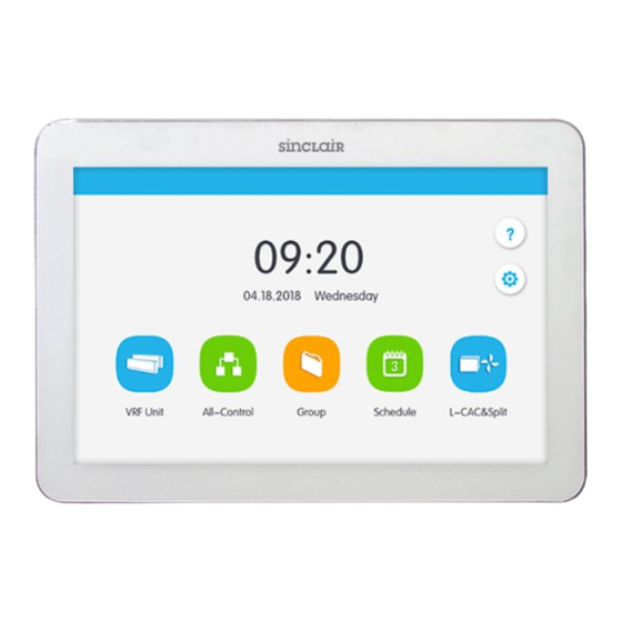
Centralized Controller DISPLAY AND WORKING INSTRUCTIONS Figure 4-1 Main Page Main Page Display and Buttons Name Instructions The present date, week and time Time zone Press this button to enter Help Info page Help button Press this button to enter setting page Setting button Press this button to enter UNI SPLIT Single-Control button... -
Page 14: General Buttons
Centralized Controller Press this button to enter group page Group button Press this button to enter All-Control page All-Control button General Buttons Display Meaning Display Meaning Name Name Press this button Press this button to to cancel the return to the previous current setting and Return Cancel... -
Page 15: Buttons Working Instructions
Centralized Controller On the IDU sort On the IDU sort page, page, Press this Backw Press this button to button to move the Forward move the selected IDU selected IDU Shift Shift forward one place backward one place Press this button to conduct shield Press this button to function of wired... -
Page 16: Functions Description
Centralized Controller (5) Zone button On the management pages of schedule, as indicated in fig.4–2 (the home page of schedule), each rectangle frame constitutes a zone button. Press the zone button, then the turning on/off of corresponding function or the corresponding page will pop in. Figure 4-2 Zone Buttons on the Homepage of Schedule FUNCTIONS DESCRIPTION Help Info... - Page 17 Centralized Controller Figure 5-6 All-Control Page All-Control Function can operate all indoor units as below: (1) ON/OFF Press ON/OFF button to turn on or turn off all units. When turning off the unit, the setting for mode, temperature, fan speed and swing is unavailable.
-
Page 18: Schedule Management
Centralized Controller Schedule Management On the homepage,press button to enter into the page of schedule management. Figure 5-8 Page of Schedule... - Page 19 Centralized Controller Figure 5-9 Page of Schedule Editing (1) Open the schedule Press the zone button to open or close the schedule. When the icons and texts turn bule indicating the schedule is open. When the icons and texts turn grey indicating the schedule is closed. When schedule is open, centralized controller will send out the control order automatically according to the time and parameters set by the schedule.
-
Page 20: Single-Control
Centralized Controller 3) Repeat schedule Press “Repeat Setting” button to enter the setting page. User can set the schedule work repeatedly according to weeks. 4) Time setting Press the “ON Time” or “OFF Time” button to enter the page of time setting. - Page 21 Centralized Controller Figure 5-10 Single-Control homepage Name Instructions Display the list of units controlled by the central display zone controller. Press the button to enter the control page of a single unit. Bright icon indicates the corresponding unit is icon buttons ON and dark icon indicates the corresponding unit is OFF Press and hold the icon to enter the page of name and icon settings.
-
Page 22: General Control Parameters
Centralized Controller unit icon Display the current unit icon unit name Display the current unit name Before using, press the registration icon and enter the registration page. Register theUNI SPLIT or MULTI VARIABLE units that are going to be controlled. Centralized controller can support the control of 36 units at most. Press and holdSingle-Control icon for 5S to enter the page of settings. -
Page 23: Advanced Control Parameters
Centralized Controller When unit is turned off, mode, temperature, fan speed and swing can’t be set. (2) Mode setting Press the Mode buttons to set UNI SPLIT unit operation mode. Modes for indoor units of different series are not all the same.If a certain mode is not available in the indoor unit, the icon of the corresponding mode cannot be selected. -
Page 24: Local Setting
Centralized Controller Figure 5-12 advanced page (1) The functions of Sleep, Quiet, Blow, Absence, Energy Saving are only effective under ON status. (2) Absence function can only be enabled in Heat mode. When Absence function is enabled, set temperature is 8℃. (3) When All Shield function is enabled, other shield buttons are ineffective. - Page 25 Centralized Controller Press the “Local Setting” button to switch to the setting options of the current unit. Select the needed option at the left side column. Sliding up and down can turn over the page. Set the corresponding content at the right side. Local setting includes: (1) Sound, temperature unit, time format, mutual exclusion Press the button to select one kind of setting.
- Page 26 Centralized Controller (7) Customer Service User can set the name and phone number of the local customer service center for the convenience of acquiring immediate solutions and technical support. Press the button to save the setting. (8) View Selecting Press the “View Selecting” button, User can select “VRF&CAC&Split”、”VRF Unit View”...
-
Page 28: Technical Support
SINCLAIR CORPORATION Ltd. 1-4 Argyll St. London W1F 7LD Great Britain www.sinclair-world.com This product was manufactured in China (Made in China). REPRESENTATIVE SINCLAIR Global Group s.r.o. Purkynova 45 612 00 Brno Czech Republic TECHNICAL SUPPORT SINCLAIR Global Group s.r.o. Purkynova 45...