Panasonic EP-MA10 Service Manual
Massage lounger
Hide thumbs
Also See for EP-MA10:
- User manual ,
- Operating instructions manual (64 pages) ,
- Operating instructions manual (28 pages)

Related Manuals for Panasonic EP-MA10


Summary of Contents for Panasonic EP-MA10
-
Page 1: Specifications
EP-MA10 ORDER NO. HPD1008U17CE MASSAGE LOUNGER EP-MA10 CANADA SPECIFICATIONS ©2010 Panasonic Electric Works Co., Ltd. All rights reserved. Unauthorized copying and distribution is a violation of law. - 1 -... -
Page 2: Table Of Contents
EP-MA10 ORDER NO. HPD1008U17CE Contents PAGE 1 SPECIFICASTIONS………………………………………………………………………………………………………………………3 2 TURNING ON THE POWER……………………………………………………………………………………………………………6 3 REQUIRED TOOLS………………………………………………………………………………………………………………………7 4 DISASSEMBLY……………………………………………………………………………………………………………………………8 5 CHECKING………………………………………………………………………………………………………………………………38 6 AIR BAG PRESSURE…………………………………………………………………………………………………………………42 7 SECRET MODE…………………………………………………………………………………………………………………………44 8 EXPLODED VIEW………………………………………………………………………………………………………………………50 9 REPLACEMENT PARTS LIST…………………………………………………………………………………………………………55 - 2 -... -
Page 3: Specificastions
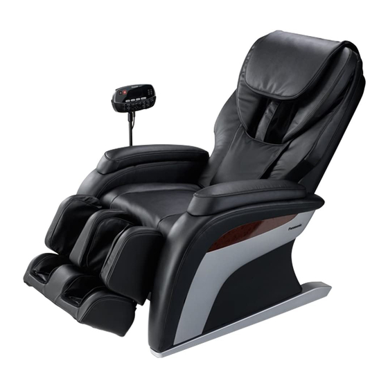
EP-MA10 ORDER NO. HPD1008U17CE 1.COMPONENTS IDENTIFICATION 1. MASSAGE LOUNGER 1 - 3 -... - Page 4 EP-MA10 ORDER NO. HPD1008U17CE 1.2 CONTROLLER - 4 -...
- Page 5 EP-MA10 ORDER NO. HPD1008U17CE - 5 -...
-
Page 6: Turning On The Power
EP-MA10 ORDER NO. HPD1008U17CE 2. TURNING ON THE POWER Plug the power into power socket. Turn the lock switch to the open position. Turn on the power switch on the power source switch box. ・When the operating lock switch is pointing toward ‘lock’, the power switch cannot be moved to the ‘on’ position. -
Page 7: Required Tools
EP-MA10 ORDER NO. HPD1008U17CE 3. REQUIRED TOOLS - 7 -... -
Page 8: Disassembly
EP-MA10 ORDER NO. HPD1008U17CE 4. DISASSEMBLY 4.1. Disassembling Rear Cushion and Armrest 1.Unhook two hooks on each side by slotted screwdriver, etc. 2.Remove two Hexagonal bolts. Unscrew four hexagonal bolts on the Controller stand. 3.Remove Armrest by lifting up the Armrest. - Page 9 EP-MA10 ORDER NO. HPD1008U17CE 4.2. Removing the Seat 1.Proceed all the procedures of 4.1 Removing the Armrest. 2. Remove each Push-turn rivet. 3. Pull out the zippers out, cut the Cable tie, and open the zippers which connect the Seat with the Ottoman.
- Page 10 EP-MA10 ORDER NO. HPD1008U17CE 6. Cut the Cable ties which connect with the right Seat sensor cords of the Seat. Disconnect Connectors. 4.3. Removing the Ottoman 1.Execute all the procedures of 4.1 Removing the Armrest. 2. Execute all procedures of 4.2 Removing the Seat.
- Page 11 EP-MA10 ORDER NO. HPD1008U17CE 4.Remove four Push-turn rivets and remove H.. 5.Remove the Hoses. 6.Remove the Snap pin which fixes the Ottoman lift units - 11 -...
- Page 12 EP-MA10 ORDER NO. HPD1008U17CE 7.Remove the Hinge pin B, Resin bushing, and U nut on both sides of the Ottoman, and remove the Ottoman. 4.4. Disassembly of the Ottoman 1.Proceed all the procedures of 4.3Removing the Ottoman. 2.Remove two Screws and remove K 3.Unzip two zippers.
- Page 13 EP-MA10 ORDER NO. HPD1008U17CE 4.Remove Hoses from hole of the Cloth cover and remove one spring and one hose in order to remove Air ottoman cloth. 5.Remove Snap pins by pliers and remove left and right pins in order to separate the Ottoman to both upper and lower sides.
- Page 14 EP-MA10 ORDER NO. HPD1008U17CE 7.Remove each Air bag as the Figure. CAUTION Allocate and connect Hoses as the Figure. CAUTION Be careful of the directions of the Sole shiatsu sheets. - 14 -...
- Page 15 EP-MA10 ORDER NO. HPD1008U17CE 4.4. Removing the Massage mechanism block. 1. Unscrew four screws and remove the Rear cover. CAUTION When installing the Rear cover, do not push Rib to outside of the Rear cover. 2. Unscrew three screws and left Rail pieces, put the jig.
- Page 16 EP-MA10 ORDER NO. HPD1008U17CE 3. Unscrew three screws and remove right Rail piece. CAUTION Hold the Massage mechanism block so as not to make it fall down. 4.Remove the Tool while holding the Massage mechanism block. CAUTION Be careful of the Massage mechanism block.
- Page 17 EP-MA10 ORDER NO. HPD1008U17CE 6.Remove two Massage mechanism block cover clips and two screws and remove the Massage mechanism block cover 7. Remove each Lead wire and remove the Massage mechanism block totally. Caution in installing Install the Guide roller spring, Washer, and Guide roller.
- Page 18 EP-MA10 ORDER NO. HPD1008U17CE If you cannot move the Massage mechanism block up and down due to the malfunction of the Up/down motor, move the Massage mechanism block as follows: 1. Necessary products Air hose x 1pc (approx. 8cm) Bit x 1pcs (approx. 8cm) Electric screwdriver x 1pc Install the air hose on the bit.
- Page 19 EP-MA10 ORDER NO. HPD1008U17CE 8. Remove the Cords and screws, cut the Cable ties, and remove Connectors and the Cover clip. 9. Turn Up/down sensor plate (counterclockwise from upward) and move the Massage mechanism block up (six revolutions). 10. Holding the Guide roller, remove the Massage mechanism block.
- Page 20 EP-MA10 ORDER NO. HPD1008U17CE 4.5. Installing the Massage Mechanism Block 1.Pushing the Massage mechanism block down, turn Up/down sensor plate (counterclockwise from upward). Move the Massage mechanism block till it gears with each other. 2.Put the Massage mechanism block and install two Rail piece sets.
- Page 21 EP-MA10 ORDER NO. HPD1008U17CE 3.Referring to the 4.10.7. Adjustment of Massage mechanism block up/down sensor gear, move the Massage mechanism block to the central position. 4.6. Removing the Massage Wheel Cover 1.Execute all the procedures of 4.1. Removing the Armrest.
- Page 22 EP-MA10 ORDER NO. HPD1008U17CE 4. Unscrew two screws on the Sub frame cover. 5.Back frame can be removed after unscrewing two nuts (left/right each). Points of Assembly Before installing the Back frame, put Cords into holes of the Massage wheel cover.
- Page 23 EP-MA10 ORDER NO. HPD1008U17CE 4.7. Removing the Sub PCB 1. Execute all the procedures of 4.1. Removing the Armrest. 2.Unscrew six screws (three for each left/right) and remove foot cover (left/right). 3. Unscrew four screws (two for each left/right) and remove Under box top.
- Page 24 EP-MA10 ORDER NO. HPD1008U17CE CAUTION When disconnect the Connectors, pull them out preshing the part shown in the Figure 4.8. Removing the Ottoman Lift Units Execute all the procedures of 4.1 Removing the Armrest and 4.7 Removing the Under box.
- Page 25 EP-MA10 ORDER NO. HPD1008U17CE 4.9. Removing the Reclining Lift Unit 1.Execute all the procedures of 4.1 Removing the Armrest and 4.7 Removing the Under box. 2. Removing the two Connectors on the Sub PCB, as the Figure. 3.Remove the Hinge pins and Snap pins. Remove the Ottoman lift unit from the Main frame.
- Page 26 EP-MA10 ORDER NO. HPD1008U17CE 4.10. DISASSEMBLY OF MASSAGE MECHANISM BLOCK 4.10.1. Allocation of the Lead wires Allocation of the Connecting plate, each sensor and its parts, and fixing of the Cable ties are as follows: - 26 -...
- Page 27 EP-MA10 ORDER NO. HPD1008U17CE 4.10.2. Removing the Tapping rotation sensor, Up/down sensor, Intensity sensor, and Tapping motor 1. Disconnect four Connectors (CN5、CN9、CN10、CN11)and cut two Cable ties T30R on the Connecting PCB 2.Unscrew one Screw and remove the Intensity sensor install plate.
- Page 28 EP-MA10 ORDER NO. HPD1008U17CE 5.Remove the Belt and unscrew three screws, and remove the Tapping motor with the Tapping motor install plate. 6. Disassemble each part. Be careful of the directions of the Motors when installing the parts. - 28 -...
- Page 29 EP-MA10 ORDER NO. HPD1008U17CE 4.10.3. Removing the Up/down motor and the Up/down rotation sensor 1. Disconnect two connectors(CN4, CN8)and cut one Cable tie (T30R) on the Connecting PCB. 2.Unscrew three screws and remove the Up/down rotation reinforcement plate. 3.Unscrew one screw and remove the Up/down sensor install plate.
- Page 30 EP-MA10 ORDER NO. HPD1008U17CE 4.Unscrew six screws and remove the Up/down motor block. 5.Disassemble each part. Be careful of the directions of the Motors when installing the parts. - 30 -...
- Page 31 EP-MA10 ORDER NO. HPD1008U17CE 4.10.4. Removing the Intensity motor 1.Disconnect all the connectors on the Connecting PCB. 2.Remove four screws and the PCB install plate. 3.Remove four screws and Intensity motor block. 4.Disassemble each parts. Be careful of the direction of the Motor when installing them.
- Page 32 EP-MA10 ORDER NO. HPD1008U17CE 4.10.5. Removing the Massage driving block 1.Unscrew two screws and remove the Intensity reinforcement plate top cover. 2. Unscrew one screw and remove the Massage sensor install plate. 3. Remove two Brushclips. 4.Unscrew four screws and remove the Massage driving block.
- Page 33 EP-MA10 ORDER NO. HPD1008U17CE 5. Unscrew two screws and remove the Sensor plate. - 33 -...
- Page 34 EP-MA10 ORDER NO. HPD1008U17CE 4.10.6. Removing the Massaging motor 1.Execute all the procedures of 4.10.2 Removing the Tapping motor. 2.Execute all the procedures of 4.10.3 Removing the Up/down motor and the Up/down rotation sensor. Unscrew the Screws (four Screws on the right and ten on the left) which fit up the Intensity gear reinforcement plate.
- Page 35 EP-MA10 ORDER NO. HPD1008U17CE 4. Unscrew two screws on the Intensity reinforcement plate Top cover. 5.Unscrew two screws on the Intensity shaft holder stand 6.Open the Gear box inserting a slotted screwdriver in the indicated spot. After the Motor is removed from the Gear box.
- Page 36 EP-MA10 ORDER NO. HPD1008U17CE Point When installing the Motor, the assembly would be easier if you insert the Motor plate to the ditch of the Intensity gear the left side first and install the right side. Caution When installing the Motor, make sure that the Connecting cord is on the top.
- Page 37 EP-MA10 ORDER NO. HPD1008U17CE 4.10.7. Adjustment of Massage mechanism block up/down sensor gear You need to adjust the Up/down sensor gear after re-installing the Massage mechanism block to the Rear frame, because the position of the Up/down sensor gear is changed.
-
Page 38: Checking
EP-MA10 ORDER NO. HPD1008A16CE 5.CHECKING - 38 -... - Page 39 EP-MA10 ORDER NO. HPD1008A16CE - 39 -...
- Page 40 EP-MA10 ORDER NO. HPD1008A16CE - 40 -...
- Page 41 EP-MA10 ORDER NO. HPD1008A16CE - 41 -...
-
Page 42: Air Bag Pressure
EP-MA10 ORDER NO. HPD1008A16CE 6. Checking pressures of Air bags 1. Cut the Cable tie of hose and remove the Hose plugs. 2. Insert Hose of the Air pressures to T-shaped joint. 3. Connect to the each Hoses as the Figure. - Page 43 EP-MA10 ORDER NO. HPD1008A16CE 4.Press On/off button, Leg massage button and take a measurement of the Maximum value for two minutes. 5. Take measurements pressures of three levels. If the values are within the standard as shown below, Air bags, Pump, and Air hoses are OK.
-
Page 44: Secret Mode
EP-MA10 ORDER NO. HPD1008A16CE 7. SECRET MODE 7-1.Preparation procedures of the Secret mode First, before making access to each Secret modes, execute the following ‘’Preparation procedures of the Secret mode’’. Connect the Power cord to the power source, and turn OFF the Power source switch box. - Page 45 EP-MA10 ORDER NO. HPD1008A16CE 7-2.Indication of the total use time C0 1.First, execute the procedures of 7.1. Preparation procedures of the Secret mode. 2.Push Left and Right ④ buttons till the CO is shown and push ⑤ button. 3.Push ⑤ button again, then the digit of ‘’1,000’’ blinks and the number is shown on the display.
- Page 46 EP-MA10 ORDER NO. HPD1008A16CE 7-3.Indication of each operation time C3 1.First, execute the procedures of 7.1. Preparation procedures of the Secret mode. 2.Push Left and Right buttons ④ till the C3 is shown and push ⑤ button. 3.Push ④button again, and push Left and Right buttons ④buttons till the necessary mode is shown.
- Page 47 EP-MA10 ORDER NO. HPD1008A16CE 7-5. Indication of the malfunction analysis -②【C7】 It shows in which operation the Massage chair stopped abnormally. 1.First, execute the procedures of 7.1. Preparation procedures of the Secret mode. 2.Push Left and Right ④ buttons till the C7 is shown and push ⑤ button. Some of the following is show.
- Page 48 EP-MA10 ORDER NO. HPD1008A16CE 7-7.Manual operation procedures of Massage mechanism block CE Use the manual operation when you remove the Massage mechanism block from the Massage chair or install it or check each operation. (You can check each operations of Up/down, Width, Intensity, and Tapping motors.) 1.First, execute the following procedures of 8.1 Preparation procedures of the Secret mode.
- Page 49 EP-MA10 ORDER NO. HPD1008A16CE ● Sounds during Knead upwards and downwards operation You may feel some vibration in the operations of Knead upwards and Knead downwards, however this phenomenon is caused structurally and it is not abnormal. This is the noise of backlash by the Worm wheel and the Worm shaft;...
-
Page 50: Exploded View
EP-MA10 ORDER NO. HPD1008A16CE 8. EXPLODED VIEW - 50 -... - Page 51 EP-MA10 ORDER NO. HPD1008A16CE - 51 -...
- Page 52 EP-MA10 ORDER NO. HPD1008A16CE - 52 -...
- Page 53 EP-MA10 ORDER NO. HPD1008A16CE - 53 -...
- Page 54 EP-MA10 ORDER NO. HPD1008A16CE - 54 -...
-
Page 55: Replacement Parts List
EP-MA10 ORDER NO. HPD1008A16CE 12. REPLACEMENT PARTS LIST NOTES: Ref.No. Part No. Part Name & Description Remarks Per Unit WEPMA10L0088 REAR FRAME WEP1273L0698 RAIL PIECE WEP1273L6118 SCREW WEPMA10L0628 REAR COVER FIXING PLATE WEP1272L6218 SCREW WEP2005L0687 CORD FOR WIRE WEP1273L6318 BOLT... - Page 56 EP-MA10 ORDER NO. HPD1008A16CE Ref.No. Part No. Part Name & Description Remarks Per Unit WEP3530L9667 SCREW WEP3530L0927 HINGE PIN B WEP3530L6937 V LOCK NUT WEPMA10L0188 MULTI ACTION SPRING WEP3530L0567 FOOT COVER WEP3530L0307 FOOT PIPE WEP3200L0937 HINGE PIN MINI WEP1280L0827 LEG LARGE AIR BAG RIGHT...
- Page 57 EP-MA10 ORDER NO. HPD1008A16CE Ref.No. Part No. Part Name & Description Remarks Per Unit WEPMA10L2058 CONNECTING CORD FOR SEAT B WEPMA10L2068 CONNECTING CORD FOR POWER SOURCE B WEPMA10K3608 MASSAGE WHEEL COVER K, 202 WEPMA10K3188 REAR COVER, 202 WEPMA10K3618 SEAT K, 202...
- Page 58 EP-MA10 ORDER NO. HPD1008A16CE Ref.No. Part No. Part Name & Description Remarks Per Unit * WEP545H1937 GUIDE ROLLER B * WEP578AL0317 RUBBER RING * WEPMS40L4677 UP/DOWN SENSOR DRIVING GEAR * WEPMS40L0327 UP/DOWN SHAFT HOLDER * WEPMS40L1007 UP/DOWN MOTOR * WEPMS40L2197 UP/DOWN ROTATION SENSOR *...