Table of Contents
Advertisement
Quick Links
- 1 He Xltek Emu40Ex Eeg Headbox Requires Competent User Input and Its Output Must be Reviewed and Interpreted by Trained Medical Professionals Who will Exercise Professional Judgement in Using this Information
- 2 Emu40Ex Breakout Box
- 3 Maintenance
- 4 Maintenance, Cleaning, & Disposal
- 5 Troubleshooting
- Download this manual
Advertisement
Table of Contents

Related Manuals for natus Xltek EMU40EX


Summary of Contents for natus Xltek EMU40EX
- Page 1 ™ ® Xltek EMU40EX with Natus Base p/n 013926 User and Service Manual...
- Page 2 This copy of the User Manual shall be used only in accordance with the conditions of sale of Natus Medical Incorporated or its distributors. Natus Medical Incorporated makes no representations or warranties of any kind whatsoever with respect to this document.
-
Page 3: Table Of Contents
Table of Contents INTRODUCTION ............................5 .......................... 6 RODUCT NTENDED XLTEK EMU40EX EEG H EADBOX REQUIRES COMPETENT USER INPUT AND ITS OUTPUT MUST BE REVIEWED AND INTERPRETED BY TRAINED MEDICAL PROFESSIONALS WHO WILL EXERCISE PROFESSIONAL ..................... 6 JUDGEMENT IN USING THIS INFORMATION ........................ - Page 4 ® EMU40EX™ User and Service Manual Xltek SPECIFICATIONS: EMU40EX AMPLIFIER ....................27 PRODUCT IMAGES ........................... 30 EMU40EX S ..........................30 YSTEM ............................. 31 EMU40EX B ........................32 REAKOUT UNPACKING .............................. 33 SETTING UP ............................... 34 ......................34 ONNECTING TO THE COMPUTER USB-S ........................
- Page 5 ® EMU40EX™ Xltek User and Service Manual ........................53 MPLIED ICENSE ..........................53 NDICATIONS FOR ..........................53 NSTRUCTION FOR ......................53 OW THE ULSE XIMETER ORKS ......................55 ULSE XIMETER CCESSORIES ....................... 55 VAILABLE XIMETER ENSORS ............................. 56 EASUREMENTS ..................56 AUSES OF NACCURATE EASUREMENTS...
-
Page 6: Introduction
Standard TCP/IP or USB connectivity is supported for quick and easy installation. The Natus base unit offers TCP/IP and USB connectivity for quick and easy installation. This rugged device was designed with extensive clinical input to meet the workflow and application needs of the EEG, LTM, or PSG Lab. -
Page 7: Product Intended Use
Interruptions in signal transmission resulting from external electromagnetic events. (Ex: Electrocautery, Operation of wireless equipment in close proximity to the amplifier, etc.) Any form or random or intermittent system behaviour. If any of the above are observed or if unusual system behaviour is observed contact Natus Technical support. -
Page 8: Using The Manual
® EMU40EX™ User and Service Manual Xltek Using the Manual This manual provides basic information and instructions that will enable you set up and operate the EMU40EX amplifier. When going through the procedures, we recommend that you read the whole section first, before starting the sequence. -
Page 9: Emu40Ex Safety And Standards Conformity
® EMU40EX™ Xltek User and Service Manual EMU40EX Safety and Standards Conformity Standards of Compliance and Normative References Multichannel Sleep/EEG Amplifier System, Model EMU40EX, detachable cord connected, portable 115/230Vac, 50/60Hz, 30W. Type of protection against electric shock: Class I Degree of protection against electric shock: Type BF Degree of protection against ingress of water: IPX0 Degree of safety of application in the presence of a flammable anaesthetic mixture with air or with oxygen or nitrous oxide: Equipment not suitable for use in the presence of a flammable... - Page 10 ® EMU40EX™ User and Service Manual Xltek Table 2 – EMC Standard of Compliance and Normative References Medical electrical equipment – Part 1-2: General IEC 60601-1-2:2007, Edition 3.0 requirements for safety – collateral standard: electromagnetic compatibility – requirements and tests IEC 61000-4-2:2008, ed 2.0 Electromagnetic Compatibility (EMC) Part 4-2: Testing and Measurement Techniques - Electrostatic Discharge Immunity...
-
Page 11: Declaration Of Compliance For Iec 60601-1-2
® EMU40EX™ Xltek User and Service Manual Declaration of Compliance for IEC 60601-1-2 Table 1 - Electromagnetic Emissions Guidance and manufacturer’s declaration – electromagnetic emissions The EMU40EX is intended for use in the electromagnetic environment specified below. The customer or the user of the EMU40EX should assure that it is used in such an environment. - Page 12 ® EMU40EX™ User and Service Manual Xltek Table 2 - Electromagnetic Immunity Guidance and manufacturer’s declaration – electromagnetic immunity The EMU40EX is intended for use in the electromagnetic environment specified below. The customer or the user of the EMU40EX should assure that it is used in such an environment. Immunity Test IEC 60601 Compliance...
- Page 13 ® EMU40EX™ Xltek User and Service Manual Table 3 - Electromagnetic Immunity– for EQUIPMENT and SYSTEMS that are not LIFE- SUPPORTING Guidance and manufacturer’s declaration – electromagnetic immunity The EMU40EX is intended for use in the electromagnetic environment specified below. The customer or the user of the EMU40EX should assure that it is used in such an environment Immunity test IEC 60601...
-
Page 14: Declaration Of Compliance For Fcc
® EMU40EX™ User and Service Manual Xltek Table 4 - Recommended Separation Distances Recommended separation distances between portable and mobile RF communications equipment and the EMU40EX. The EMU40EX is intended for use in an electromagnetic environment in which radiated RF disturbances are controlled. -
Page 15: Contraindications, Warnings, And Cautions
To ensure the validity of signals, do not operate the device near any sources of electromagnetic interference. Natus systems are not AP or APG rated. DO NOT USE a Natus system in the presence of a flammable anesthetic mixture with air, oxygen, or nitrous oxide. -
Page 16: Warnings And Cautions
Never use equipment that has parts missing or equipment that might contain loose parts inside of it (that is, inside an enclosed portion of the equipment). If you suspect a piece of equipment has missing or loose parts, contact Natus. Routinely inspect system cables and components for regular wear and tear. -
Page 17: Electrical Warnings And Cautions
® EMU40EX™ Xltek User and Service Manual The EMU40EX cannot be cleaned of bio-contaminate. Attempts to remove bio-contaminate will damage the unit. Device accessories may include several kinds of disposable, sterile needle electrodes. These needles are labeled as STERILE, and the method of sterilization is documented on the packaging. - Page 18 When replacing the fuse for the EMU40EX, it must be replaced by a fuse with the same type and rating as the original fuse. Replacement fuses should be purchased from Natus directly. The EMU40EX amplifier system is classified as a class I device according to IEC 60601-1.
-
Page 19: Patient Environment Warnings And Cautions
® EMU40EX™ Xltek User and Service Manual WARNING: ELECTRICAL SHOCK HAZARD: Do NOT turn on the system power until all cables have been connected, verified and visually inspected for any damage. Failure to inspect the cables may result in electrocution. Verification of electrical safety should be performed routinely. -
Page 20: Pulse Oximeter Warnings
® EMU40EX™ User and Service Manual Xltek No parts of the Medical Electrical equipment shall be serviced or maintained while in use with a patient. Patient connections are NOT intended for direct cardiac contact. Route patient cabling carefully to reduce the possibility of patient entanglement or strangulation. -
Page 21: Pulse Oximeter Sensor Warnings
® EMU40EX™ Xltek User and Service Manual Excessive patient movement may cause inaccurate measurements. Venous pulsations may cause inaccurate measurements. Carboxyhemoglobin may erroneously increase readings. The level of increase is approximately equal to the amount of carboxyhemoglobin present. Dyes, or any substance containing dyes, that change usual arterial pigmentation may cause erroneous readings. -
Page 22: Wireless Option Warnings And Cautions
Refer to Table 4 in the Declaration of Compliance for IEC 60601-1-2 section. Should interference with the wireless radios in this device occur, relocate the devices causing the issue, or contact Natus Technical Support at 1-800-303-0306 or OTS@Natus.com. -
Page 23: Electromagnetic Interference (Emi) Warnings
Natus is not responsible for any injury or damage that may result from inadequate, poorly constructed, or unapproved transports, carts, or operating surfaces. Natus is not responsible for any injury or damage that may result from improper cable storage during transport. -
Page 24: Procedures And Warnings
® EMU40EX™ User and Service Manual Xltek Procedures and Warnings Electrostatic Disacharge (ESD) Handling Before performing any setup or placement procedures, read the precautions outlined in this section. WARNING: Be sure to take the appropriate Electrostatic Discharge (ESD) precautions. Disconnect the cables before moving, cabling, or performing any set up procedures. Some semiconductor (solid state) devices can be easily damaged by static electricity. - Page 25 ® EMU40EX™ Xltek User and Service Manual Follow these techniques to help identify the sources, and to increase the immunity towards parasitical noise: o Verify the power supply and all portable multiple socket-outlets are off the flo r and in a dry location. ...
-
Page 26: Description Of Symbols
® EMU40EX™ User and Service Manual Xltek Description of Symbols Symbol Description ATTENTION: Consult Accompanying Documents Consult Accompanying Documents Consult Operating Instructions Pushing Prohibited Protective Earth (Ground) Type BF Equipment Dangerous Voltage Alternating Current Direct Current Power On Power Off EU only: Do Not Dispose as Unsorted Municipal Waste Class II Equipment (non-grounded enclosure) - Page 27 ® EMU40EX™ Xltek User and Service Manual Symbol Description ESD Sensitive Static Sensitive DC Inputs 13 to 16 Breakout Cable Connector Patient Event Button Connector Equipotential stud Non-Waterproof Device LAN Connection USB Connection Manufacturer Information Fragile No protection against ingress of water according to IEC 60529. IPX0 Protection from dripping water from above the device for at least 10 minutes IPX1...
-
Page 28: Specifications: Emu40Ex Amplifier
TCP/IP (Fixed IP address or DHCP) Wired Gigabit Ethernet (1000BASE-T, IEEE 802.3ab) Direct Connection Interface USB 2.0 User Interface Front Panel Control Base Unit LCD Touchscreen Patient Event Pushbutton Connection 1 on Base Unit, 1 on Breakout Box Photic Stimulator Interface 1 Natus Photic Stimulator... - Page 29 ® EMU40EX™ Xltek User and Service Manual Specification Value(s) Digital Specifications Sampling Frequency 256 Hz, 512, 1024 Hz Sampling Resolution – EEG Channels 16 bits Sampling Quantization – EEG Channels 300 nV Sampling Resolution - DC Channels 16 bits Sampling Quantization – DC Channels 150 μV Modes of Operation Base Unit Fuse Type and rating...
- Page 30 10%–95% Transport and Storage Atmospheric Pressure Range 500 hPa to 1060 hPa Dimensions Size (length x width x height) Natus Base Unit 292.5mm x 266.6mm x 51.5mm (11.52” x 10.5” x 2.03”) EMU40EX Breakout 100mm x 158mm x 23mm (3.94’’ x 6.22’’ x 0.91’’)
-
Page 31: Product Images
® EMU40EX™ Xltek User and Service Manual Product Images EMU40EX System Figure 1: EMU40EX System: Base Unit, Breakout Box and Battery Pack... -
Page 32: Base Unit
Reserved for future use. Labeled with Can be used to connect DC signals from external devices. Labeled with DC1-DC12. Only DC1-DC4 are available when EMU40EX Breakout Box is connected. Natus Photic Stimulator Connector. Labeled with Patient Event Button Connector. Labeled with... -
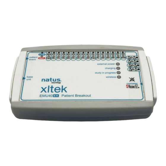
Page 33: Emu40Ex Breakout Box
® EMU40EX™ Xltek User and Service Manual Used to connect the Base Unit to the Quantum Patient Breakout Box. Not available when EMU40EX Breakout Box is connected. Used to connect the Patient Breakout Box for the EMU40EX. Labeled with NOTE: Only one type of breakout box should be used at a given time. You cannot use an EMU40EX breakout in conjunction with another breakout box. -
Page 34: Unpacking
Ethernet Cable Power Cord Patient Event Switch Optional Accessories: EMU40EX Battery Pack EEG Accessory Kit NOTE: The EMU40EX system should be used only with cables, transducers, electrodes, sensor, and switches that are supplied or approved by Natus. -
Page 35: Setting Up
USB-Style Connection To connect the EMU40EX to the XLTEK computer: Use the supplied USB 2.0 cable to connect the Natus Base Unit to the computer. Insert the Patient Event Switch into the Patient Event connection on the Base Unit or Breakout. -
Page 36: Connection Setup For The Base Unit
Connect the power cable, Base Unit to EMU40EX Breakout Cable, patient event switch, and any additional accessories as required. NOTE: Setup and Installation of the EMU40EX amplifier system should be performed by Natus qualified personnel only. -
Page 37: Setting The Ip Address
® EMU40EX™ Xltek User and Service Manual Setting the IP Address 1. To power-up the Base unit, press and hold power button for 3 seconds. The following user interface appears. 2. Press the Settings button on the touchscreen to access the IP Configuration. NOTE: The amplifier supports both DHCP and static TCP/IP address configuration. - Page 38 ® EMU40EX™ User and Service Manual Xltek 3. Select On or Off for Audio Alerts. 4. Select DHCP under Network Settings otherwise, the DNS server will enable manual entry of the IP address and DNS server for the Base Unit. 5.
- Page 39 ® EMU40EX™ Xltek User and Service Manual 7. From the Main Screen, confirm system setup by pressing the Info button to view the information screen. 8. On the information screen, ensure that the IP address is set as intended, and that the connection information related to the Breakout show that all components are recognized by the system.
-
Page 40: Touchscreen Icons
Xltek Touchscreen Icons When properly installed and connected to the PC, the Natus Base displays several icons at the bottom of the touchscreen which indicate the connectivity status of the breakout boxes, the headbox, and the base units. The following table shows the different connection status indicators. -
Page 41: Amplifier Usage And Features
Beginning a study Once the equipment has been installed by your Natus qualified representative and a patient has been connected to the EMU40EX system, a new EEG study can be started. For details on beginning a new EEG study, consult the NeuroWorks manual. -
Page 42: Adding The Emu40Ex Breakout Box To A Lanyard Or Belt
® EMU40EX™ User and Service Manual Xltek Adding the EMU40EX Breakout Box to a Lanyard or Belt Belt Setup To use the belt setup: 1. Attach the pouch to the belt by threading the belt through the back of the pouch. 2. -
Page 43: Potential Equalization Conductor
® EMU40EX™ Xltek User and Service Manual Lanyard Setup To use the lanyard setup: 1. Attach the lanyard to the two (2) rings on the back of the pouch. 2. After attaching the electrodes to the patient, place the Breakout Box into the pouch with the electrode wires exiting at the top or on the sides, as required. -
Page 44: Emu40Ex Amplifier System Description
The EMU40EX Amplifier System is designed to work with an XLTEK host computer system running the Natus Database and NeuroWorks data review and analysis software. The EMU40EX Breakout Box is a 40-channel EEG amplifier with touch-proof jacks for the EEG electrode lead-wires. -
Page 45: Feature Description Of Emu40Ex With Wireless Option Disabled
® EMU40EX™ Xltek User and Service Manual Feature Description of EMU40EX with Wireless Option Disabled When the Base Unit is physically connected to the Breakout Box, i.e. with the Breakout Box Data Cable, the EMU40EX is referred to as being in Physical Connection Mode. In this mode, the data is transmitted over the wired connection to the Base Unit, which then transmits the data to the computer. - Page 46 ® EMU40EX™ User and Service Manual Xltek When the Base Unit is physically disconnected from the Breakout Box, the EMU40EX is referred to as being in Physical Disconnection Mode. In this mode, the Breakout Box uses compact flash memory to store the study data (see Figure Figure 9 - Physical Disconnection Mode without Wireless Option...
- Page 47 ® EMU40EX™ Xltek User and Service Manual When the Breakout Box is reconnected to the Base Unit, the EMU40EX is referred to as being in Physical Reconnection Mode. In this mode, any data stored in the Breakout Box is transferred to the computer via the Base Unit and merged with the recorded study (see Figure 10).
-
Page 48: Feature Description Of Emu40Ex With Wireless Option
® EMU40EX™ User and Service Manual Xltek Feature Description of EMU40EX with Wireless Option The wireless option has no effect on wired operation. During Physically Connected Mode, data is transmitted over the wired connection to the Base Unit and then transmitted to the computer. The computer software displays and stores this data (see Figure 11). - Page 49 ® EMU40EX™ Xltek User and Service Manual When the Base Unit is physically disconnected from the Breakout Box, the Breakout Box uses compact flash memory to store the study data and simultaneously transmits a down-sampled version of this data over the wireless connection (see Figure 12).
- Page 50 ® EMU40EX™ User and Service Manual Xltek The data transmitted through the wireless connection is used by the NeuroWorks software to present a passive visualization of the EEG signals. It is not possible to perform any action on the signals presented by the software (passive signal representation).
-
Page 51: Setting The Wireless Power Limit
To verify that the EMU40EX amplifier is correctly calibrated, perform the following procedure: Connect the Base Unit to an XLTEK computer and turn on the system. Start Natus Database. To start a new study, click New EEG or Sleep. Choose Edit > Settings > Acquisition. -
Page 52: Channel Test
® EMU40EX™ User and Service Manual Xltek Set the LFF filter to 0.1, the HFF filter to OFF, and the Notch filter to OFF. Verify that no sine wave is greater than 50 microvolts peak-to-peak. 50 microvolts represents gain match to 1%. NOTE: For more information on setting up a montage, consult the online Help. -
Page 53: Impedance Check
® EMU40EX™ Xltek User and Service Manual Impedance Check An impedance check is performed to ensure that the electrode contact with the patient is satisfactory. You can perform an impedance check at any time during a study. Running an Impedance Check from the Software When an impedance check is initiated, the software scans all channels (in auto scan mode). -
Page 54: Pulse Oximeter
® EMU40EX™ User and Service Manual Xltek Pulse Oximeter ® The following topics list the specifications cleared by the FDA under K990966 for Masimo SET board that is built into the EMU40EX. The board connects to sensors and provides oxygen saturation, pulse rate, pulse waveform, and other output information via the NeuroWorks software. - Page 55 ® EMU40EX™ Xltek User and Service Manual Red and infrared light-emitting diodes (LEDs) in oximetry sensors serve as the light sources, a photodiode serves as the photodetector. Traditional pulse oximetry assumes that all pulsations in the light absorbance signal are caused by oscillations in the arterial blood volume.
-
Page 56: Pulse Oximeter Accessories
® EMU40EX™ User and Service Manual Xltek Discrete Saturation Transform (DST™) plot The DST plot has two peaks: the peak corresponding to the higher saturation is selected as the SpO value. This entire sequence is repeated once every two seconds on the most recent four seconds of raw ®... -
Page 57: Measurements
® EMU40EX™ Xltek User and Service Manual Measurements If the accuracy of any measurement does not seem reasonable, check the patient’s vital signs by alternative means. Then, check the pulse oximeter for proper functioning. Causes of Inaccurate Measurements Incorrect sensor application or use. ... -
Page 58: Transport System Specifications And Maintenance
Refer to the corresponding Instructions for Use for all system components prior to use. This should include, but is not limited to: cameras, computers, stimulators, and software. NOTE: Transportation System setup and installation should be performed by Natus qualified personnel only. -
Page 59: Natus Ergojust Cart Specifications
EMU40EX™ Xltek User and Service Manual Neurowand Cart (No PC) Specifications Natus ErgoJust Cart Specifications For specifications and details on the ErgoJust cart, please refer to the Natus ErgoJust Installation & Functionality Guide (p/n: 019667). Maximum Equipment Load [lbs] Mounting... -
Page 60: Maintenance
Make sure that any platform, table, cart, or other surface used during the operation, transport, or temporary or permanent storage of the system and its components is adequate, sturdy, and safe. Natus is not responsible for any injury or damage that may result from inadequate, poorly constructed, or unapproved transports, carts, or operating surfaces. -
Page 61: Electrical Input And Isolation Transformer Details
® EMU40EX™ Xltek User and Service Manual Electrical Input and Isolation Transformer Details Electrical Input 200-240V AC, 2.24A @ 50 Hz Isolation Transformer Powervar ABC500-22MED North America Electrical Input 120V AC, 3.10A @ 60 Hz Isolation Transformer Powervar ABC300-11MED Japan Electrical input 100V-120V AC, 8.0A, 50/60Hz Isolation Transformer... -
Page 62: Maintenance, Cleaning, & Disposal
Regular preventive maintenance does not involve access to the interior of the EMU40EX amplifier and components. For servicing problems that require corrective maintenance and/or internal component service, call Natus Technical Support at 1-800-303-0306, or contact your local XLTEK representative. -
Page 63: Disposal
At the end of the expected service life, when disposing of the EMU40EX amplifier and its components, it is recommended that federal, state, and local laws be followed for proper disposal of printed circuit boards, plastics, and metal parts. For disposal of non-Natus accessories, please follow the instructions provided with these items. -
Page 64: Troubleshooting
® EMU40EX™ User and Service Manual Xltek Troubleshooting If you are experiencing problems, try the solutions listed below. Troubleshooting Checklist Ask the patient to relax. Inspect your cables. Make sure all cables are connected properly between the EMU40EX and the computer. If using a LAN, make sure the hardware and software are configured correctly. -
Page 65: Getting Help
User and Service Manual Getting Help Natus is committed to providing you with support so you can operate the EMU40EX amplifier with ease and confidence. If you need help, follow these steps to find a solution: Step 1: Document the Incident Carefully document the incident. -
Page 66: Accessories & Replacement Parts List
Fuse, Glass 1.5A 250VAC 5X20mm Slow EEG accessories which can be used with the EMU40EX Amplifier System are available for you to browse www.natus.com in the Natus Neuro Accessories Catalog online at or via Natus Sales and Support at 1- 800-303-0306. -
Page 67: Index
® EMU40EX™ Xltek User and Service Manual Index EMC Standards ..............8 EMU40EX Pulse Oximeter ............. 53 Accessories ............... 65 Testing ................. 50 Amplifier Calibration ............... 50 Usage and Features ............40 Impedance Check ............ 52 Verification .............. 50 Wireless Disabled .............. - Page 68 Pulse Oximeter..............53 Isolation Transformer ..........60 Accessories ..............55 Maintenance ............57, 59 How it works ..............53 Natus ErgoJust Cart ............58 Inaccurate Measurements Neurowand Cart with No PC ........58 Causes ..............56 Specifications ............... 57 Indications for use ............53 XLTEK Trolley ..............
- Page 69 ® EMU40EX™ Xltek User and Service Manual Electrostatic ..............23 Warnings and Cautions ..........21 ESD ................23 Wireless Power General ................. 15 Set Limit ............... 50 Patient Environment ............ 18 Wireless Power Limit Pulse Oximeter ............. 19 Setting ................50 Pulse Oximeter Sensor ..........
- Page 70 A Total Service Solution Standing behind every XLTEK product is Natus Medical Incorporated, an internationally respected innovator of medical products and services. Our Neurology systems are backed up by an in-house support team staffed with technical and clinical experts, 24/7 support, remote support via WebEx or VPN, the largest clinical and technical field support network in Neuro/Sleep and customized service contracts that include preventative maintenance visits and computer upgrades.